Transcription
Working in theGraphics Window
mastercam x getting started tutorialsWorking in theGraphics WindowDecember 2011Be sure you have the latest information!Information might have been changed or added since this document waspublished. Contact your local Reseller for the latest information.
II WORKING IN THE GRAPHICS WINDOWMastercam X6 Working in the Graphics WindowDate: December 2011Copyright 2011 CNC Software, Inc.— All rights reserved.First Printing: December 2011Software: Mastercam X6TERMS OF USEUse of this document is subject to the Mastercam End User License Agreement.A copy of the Mastercam End User License Agreement is included with theMastercam product package of which this document is part. The MastercamEnd User License Agreement can also be found at:www.mastercam.com/legal/licenseagreement/
ContentsIntroduction . 1XTutorial Goals. 1General Tutorial Requirements . 21. Setting Standard Graphics Views (Gviews) . 5XXLesson Goals . 5Exercise 1: Changing Standard Gviews. 52. Viewing Your Part .XXXXXLesson Goals . 11Exercise 1: Viewing All Entities. 11Exercise 2: Zooming. 13Exercise 3: Spinning . 15Exercise 4: Panning. 173. Setting the Cplane and Creating a Named View .XXXXXXXX19View Menus . 19Lesson Goals . 21Exercise 1: Drawing in the Top Plane. 21Exercise 2: Drawing in the Front Plane . 25Exercise 3: Creating a New Named View for the Cplane. 28Exercise 4: Creating Geometry in the New Named View . 35Exercise 5: Introducing the View Manager . 374. Using Levels.X1141Lesson Goals . 42Exercise 1: Accessing the Level Manager. 42
IV WORKING IN THE GRAPHICS WINDOWXXXXExercise 2: Turning Level Displays On and Off. 45Exercise 3: Changing the Main Level. 46Exercise 4: Naming and Assigning Entities to a Level . 48Exercise 5: Moving and Copying Entities to a Different Level. 51Conclusion . 55XXMastercam Resources . 55Mastercam Documentation . 56Contact Us . 57
INTRODUCTIONIn Mastercam, the graphics window is your workspace in the main Mastercamwindow. It is here that you view, create, and modify geometry, drafting entities, andtoolpaths.Mastercam provides many tools you can use to change the graphics window displaywhile you work with a part. This tutorial introduces some of these tools, and teachesthe basic skills you need to manage your Mastercam workspace.Tutorial Goals Use standard graphics views (Gviews) to change your perspective of entities. Change views by dynamically zooming, spinning, and panning entities inthe graphics window. Set construction planes (Cplanes), define a new plane, and draw geometryin a non-standard orientation. Use levels to manage the display of entities.
2 TUTORIAL GOALSIMPORTANT: Screen colors in the tutorial pictures were modified toenhance image quality; they may not match your Mastercam settings orthe tutorial results. These color differences do not affect the lesson orthe exercise results.General Tutorial RequirementsAll Mastercam tutorials have the following general requirements: You must be comfortable using the Windows operating system. The tutorials cannot be used with Mastercam Demo/Home LearningEdition (HLE). The Demo/HLE file format (EMCX-6) is different fromMastercam (MCX-6), and basic Mastercam functions, such as fileconversions and posting, are unavailable. Each lesson in the tutorial builds on the mastery of preceding lesson’s skills.We recommend that you complete them in order. Focus Series and Exploring Series tutorials require, at minimum, a mastery ofthe basic Mastercam skills taught in the Getting Started Series modules. Ageneral knowledge of machining principals and practices is also required. You must have a seat of Mastercam X6 Design or higher to complete most ofthe tutorials in the Getting Started Series. The Basic 2D Machining module in the Getting Started Series requires, atminimum, a seat of Mill Entry or Router Entry. The Basic 3D Machining module in the Getting Started Series requires MillLevel 3 or Router Pro. Additional files may accompany a tutorial. Unless the tutorial providesspecific instructions on where to place these files, store them in a folder thatcan be accessed from the Mastercam workstation, either with the tutorial orin any location that you prefer. The Getting Started Series tutorials are available in an Adobe Flash compatible video format. Additional tutorial videos may also be available.Contact your local Mastercam Reseller for more information. You must install Adobe Flash Player to display tutorial videos. You candownload Adobe Flash Player from www.adobe.com.WORKING IN THE GRAPHICS WINDOW
INTRODUCTION 3 All Mastercam tutorials require you to configure Mastercam to work in adefault metric or English configuration. The tutorial provides instructionsfor loading the appropriate configuration file.WORKING IN THE GRAPHICS WINDOW
4 TUTORIAL GOALSWORKING IN THE GRAPHICS WINDOW
LESSON 1Setting Standard Graphics Views(Gviews)1This lesson shows how to change the display of aMastercam part in the graphics window usingstandard graphics views (Gviews). Gviews determine the angle from which you are looking at yourpart. Selecting different Gviews makes it easier towork on different faces of your part.Every Mastercam part includes standard viewsthat correspond to the six faces of a cube (Top,Front, Back, Right side, Left side, Bottom) plus anIsometric view. The names and coordinates ofstandard views cannot be modified. However, you can define and name your owncustom views. Standard and custom views are saved with the part information,making them portable.Gviews are a type of named view that youuse to work with a part. In Mastercam,named views comprise a 2D plane with anorigin and a specific orientation.Other types of named views includeconstruction planes (Cplanes), tool planes(Tplanes), and work coordinate systems(WCS). You will learn more about settingCplanes and creating custom views inLesson 3 , “Setting the Cplane and Creating a Named View” on page 19.Lesson Goals Use Mastercam’s standard Gviews to manipulate your graphics windowdisplay.Exercise 1: Changing Standard GviewsIn this exercise, you change your Gview using Mastercam’s standard views.
6 CHANGING STANDARD GVIEWS1 Start Mastercam using yourpreferred method: Double-click Mastercam’sdesktop icon.Or Launch Mastercam from theWindows Start menu.2 Select the default METRIC configuration file:a Select Settings, Configurationfrom Mastercam’s menu.b Choose .\mcamxm.config Metric from the Current drop-down list.c Click OK.3 From the Mastercam menu bar, choose File, Open.4 Open ANGLEBLOCK-MM.MCX-6,which was provided with thistutorial. The part opens in anIsometric (ISO) Gview.5 Press [F9] to toggle the display ofthe XYZ axes on and off. Thecoordinate axes show the originand the part orientation to help youvisualize the part in 3D space.WORKING IN THE GRAPHICS WINDOW
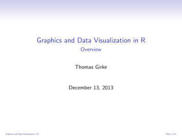
SETTING STANDARD GRAPHICS VIEWS (GVIEWS) 76 In the Status bar, located along the bottom of the Mastercam window, clickGview to open the Gview Status bar menu.This menu provides access to Gview functions and other functions you canuse to manipulate the part display in the graphics window.7 Select Top (WCS) from the menu.WORKING IN THE GRAPHICS WINDOW
8 CHANGING STANDARD GVIEWSNow you are viewing the part as if you were above it looking down.8 Practice switching to other Gviews by choosing options from the GviewStatus bar menu.TIP: You can also use GraphicsViews toolbar functions or shortcutkeys to change between standardGviews.In Mastercam menus, shortcut keyassignments appear to the right oftheir corresponding functions.9 When finished, return the part to anIsometric view, and continue withthe next lesson.WORKING IN THE GRAPHICS WINDOW
SETTING STANDARD GRAPHICS VIEWS (GVIEWS) 9WORKING IN THE GRAPHICS WINDOW
10 CHANGING STANDARD GVIEWSWORKING IN THE GRAPHICS WINDOW
LESSON 2Viewing Your Part2Mastercam provides several tools and methods for changing the appearance of thegeometry and toolpaths in the graphics window.Lesson Goals Fit all entities in a Mastercam part in the graphics window. Use zoom functions to expand your view of selected entities. Use the middle mouse button or wheel and other functions to dynamicallyspin and pan entities in the graphics window.Exercise 1: Viewing All EntitiesIn this exercise, you set up your graphics window to view all entities in a Mastercampart file.1 If you have not already done so,open the tutorial part ANGLEBLOCKMM.MCX-6, and change your Gviewto Isometric.Note: See Lesson 1, “Setting StandardGraphics Views (Gviews)” on page 5 toreview how to complete this step.
12 VIEWING ALL ENTITIES2 Choose View, Fit or press [Alt F1].The part now fills the entiregraphics window.3 Choose View, Un-zoom .8 todecrease the size of the display to80%. This creates a border of freespace around part.TIP: Un-zoom previous / .5—alsoavailable from the View menu—restores zoom to its previoussetting. If the zoom “queue”contains no previous setting, thisfunction reduces the size of thedisplayed geometry to 50% of itscurrent size.WORKING IN THE GRAPHICS WINDOW
VIEWING YOUR PART 13Exercise 2: ZoomingIn this exercise, you practice different techniques for viewing specific areas of detailin a Mastercam part.1 Place the cursor in the upper leftquadrant of the graphics window,and click the left mouse button.2 If your mouse has a middle mousewheel, spin it back and forth todynamically zoom in and out.Mastercam uses the point youclicked to anchor the center of yourzoom area.TIP: You can also press the [Page Up] and [Page Down] keys to zoom inand out.3 Fit the part to the screen (press [Alt F1]).4 Move the mouse to the lower rightquadrant. Click, and then spin themouse wheel back and forth to seethe function in another area of yourscreen.5 Fit the part to the screen. Thenchoose View, Zoom Window. Clickand drag a diagonal window asshown.WORKING IN THE GRAPHICS WINDOW
14 ZOOMING6 Click again to set the zoom window.Mastercam scales the selected areato fit the entire graphics window.7 Fit the part to the screen. Thenchoose View, Zoom Target, andclick where indicated to anchor thecenter of your selection window. Asyou move your mouse, Mastercamdraws a rectangular windowoutward in all directions from thecenter point you selected.The shape of the window changeswhen you move the mousevertically and horizontally.8 Click to set the target area.Mastercam scales the selected areato fill the entire graphics window.WORKING IN THE GRAPHICS WINDOW
VIEWING YOUR PART 15Exercise 3: SpinningThis exercise shows how to set a preference for the action your middle mouse buttonor wheel performs in the graphics window (spin or pan). You also learn to dynamically spin entities in the graphics window so that you can see them from any angle.1 Choose Settings, Configuration.2 Open the Screen property paneand, if necessary, set the Middlebutton/wheel use to Spin.3 If you changed the setting, clickApply.4 Click Yes to save the changes to your configuration file.WORKING IN THE GRAPHICS WINDOW
16 SPINNING5 Click OK to close the dialog box.6 Set up the ANGLEBLOCK-MM.MCX-6 display in the graphics window:a Set the Gview to Front.b Fit the part to the screenc Un-zoom to .8.7 Middle-click in the graphicswindow where indicated andcontinue to hold down the middlemouse button or wheel as youmove the mouse slowly in a circularmotion.This action spins the part in spaceabout the selected position and letsyou see it from any angle.8 When you finish spinning the part around, let go of the middle mousebutton/wheel to exit the function.The axes symbol (gnomon) thatdisplays the XYZ axes in thegraphics window changes as yourotate the part. Also, the Gviewname in the graphics windowchanges to “Not Saved.” Duringdynamic rotation, Mastercamcreates temporary non-standardviews.9 Return to an Isometric Gview, and fit the part to the screen.Note: You will learn more about working with non-standard views inLesson 3 , “Setting the Cplane and Creating a Named View” on page 19.WORKING IN THE GRAPHICS WINDOW
VIEWING YOUR PART 17TIPS: You can also choose DynamicRotation from the Status barGview menu or fromMastercam’s default right-clickmouse menu. You can temporarily override themiddle mouse wheel/buttonconfiguration setting and switchits behavior between spinningand panning. To do this, holddown the [Alt] key at the sametime you press the middle mousebutton/wheel in the graphicswindow.Exercise 4: PanningIn this exercise, you change your view in the graphics window as if you were movinga camera lens to the left or right, and up and down over the geometry.1 Hold down the [Alt] key, middle-click in the graphics window whereindicated, and continue to holddown the button/wheel while youmove the mouse up, down, side toside, and around.It appears that you have picked upthe part and are moving it in thedirection of the mouse. However,the entities are not physicallymoved in space, only the displaychanges.Note: The Gview does not change as you pan the entities.WORKING IN THE GRAPHICS WINDOW
18 PANNING2 When you finish panning, release the [Alt] key and the middle mousebutton/wheel at the same time to exit the function.3 To complete this exercise, use the keyboard arrow keys to pan up, down, leftand right.WORKING IN THE GRAPHICS WINDOW
LESSON 3Setting the Cplane and Creating aNamed View3This lesson introduces ways to use Mastercam views. Views are used for three mainfunctions: Graphics views (Gviews)—A Gview determines the angle from which youare looking at your part in the graphics window. Construction planes (Cplanes)—When you draw geometry, the Cplane isthe plane in which the geometry is created. The Cplane is independent ofthe Gview. For example, you can look at your part in an Isometric Gview,while drawing geometry in the Front Cplane. Lathe users can select Cplanesthat let them work in diameter or radius values. Tool planes (Tplanes)—This is the plane that is typically normal to the toolaxis. Tplanes are used only when creating toolpaths. They determine thetool orientation. In almost all cases, your Cplane will be the same as yourTplane (the most common exceptions aremill/turn operations). Work coordinate systems (WCS) - The WCS is the active coordinate systemin use by Mastercam at any given time. The WCS contains the orientation ofthe XYZ axes plus the location of the zero point (the origin). When selectinga standard view from the Gview or Planes menus, the plane you set isrelative to the current WCS. The plane you set as the WCS typically equalsthe Top, or XY, plane of the part and tells the software how your part ispositioned or oriented in the machine tool.Once you create a view, you can use it with Mastercam’s drawing and toolpathingfunctions.View MenusMost of the tools for working with views are located on the Status bar at the bottomof the Mastercam window. Each of the three view menus is selected from a differentStatus bar option:Gview, Planes, and WCS.
20 VIEW MENUS The Gview menu, the Planes menu, and the WCS menu bring up similarsets of options.Use these commands to selectstandard views. Standard viewsrepresent the different faces of acube in the current workingcoordinate system (WCS).This command lets you select aview from the catalog of savedviews, including custom views.Use these commands to createnew views from part geometryor by manipulating other views. Mastercam displays the currentview selections in the status area atthe bottom of the graphics window.The axes symbol (gnomon) showsthe current Gview orientation.WORKING IN THE GRAPHICS WINDOW
SETTING THE CPLANE AND CREATING A NAMED VIEW 21 Mastercam maintains a catalog ofviews that have been saved in thecurrent part. You can see theseviews by selecting Named Viewsfrom one of the Status bar view/planes menus (Gview, Planes,WCS).Lesson Goals Set the construction plane (Cplane) to standard Top and Front views andcreate geometry on these planes. Create your own named view and use it to create geometry on an angledplane.Exercise 1: Drawing in the Top PlaneIn this exercise, you verify CAD configuration settings for views and planes, anddraw new geometry in the Top Cplane.WORKING IN THE GRAPHICS WINDOW
22 DRAWING IN THE TOP PLANE1 Open the tutorial part 3DCUBEMM.MCX-6, and display the XYZ axesin the graphics window (press [F9]).2 Choose Settings, Configuration.3 Open the CAD Settings propertiespage and, if necessary, deselect theoptions: Update Cplane andTplane when changing Gview andReset Cplane to Top in ISO Gview.WORKING IN THE GRAPHICS WINDOW
SETTING THE CPLANE AND CREATING A NAMED VIEW 234 If you changed the setting, clickApply.5 Click Yes to save the changes toyour configuration file.6 Click OK to close the dialog box.7 Change the Gview to Top.Note: See Lesson 1, “Setting StandardGraphics Views (Gviews)” on page 5 toreview how to complete this step.The WCS, the Tplane, and theCplane have not changed, they arealso set to Top.8 To create an arc on the top of thecube, choose Create, Arc, CircleCenter Point.9 The top of the 3D cube is at 80.0mm in the Z axis. In the AutoCursorribbon bar at the top of the screen,enter a Z coordinate of 80.0, andclick the corresponding button tolock the field.WORKING IN THE GRAPHICS WINDOW
24 DRAWING IN THE TOP PLANENote: This is not the Z field in the status bar at the bottom of the Mastercamscreen - it is in the AutoCursor ribbon bar right above the function ribbonbar area.10 Click where indicated to begincreating a circle across the top ofthe cube.Note: The circle center point youchoose here is an approximate location; you do not need to specify anexact position.11 Drag and draw a circle, clickingagain to set it at a size similar tothat shown. The circle entity is a“live” entity, which means that itsattributes can be modified.12 In the Circle Center Point ribbonbar, enter a Radius of 25.0. Pressthe [Tab] key to see how theDiameter field is automatically setto 50.0.WORKING IN THE GRAPHICS WINDOW
SETTING THE CPLANE AND CREATING A NAMED VIEW 2513 Click Apply to remain in the CircleCenter Point function. (Do not clickOK.)14 Spin the entities in the graphicswindow to verify that you havedrawn the new circle across the topof the cube.Note: See Exercise 3, “Spinning” onpage 15 to review how to completethis step.15 Remain in the Circle Center Pointfunction as you advance to the nextexercise: Exercise 2, “Drawing in theFront Plane”.Exercise 2: Drawing in the Front PlaneThis exercise demonstrates Mastercam’s flexibility with changing views and planeswhen you are in a drawing function. While in the Create Circle Center Point function,you change your Cplane to the Front plane, change your Gview to a different orientation, and draw new geometry in the Front plane.WORKING IN THE GRAPHICS WINDOW
26 DRAWING IN THE FRONT PLANE1 While you are still in the CircleCenter Point function, choosePlanes, Front (WCS) from theStatus bar.2 Change your Gview to Isometric.WORKING IN THE GRAPHICS WINDOW
SETTING THE CPLANE AND CREATING A NAMED VIEW 27The Gview, Tplane, and the Cplanehave changed based on yourselections.3 Select where indicated to begincreating a circle across the front ofthe cube. Be careful to click abovethe line entity that forms thebottom side of the cube.Note: The Z coordinate in the AutoCursor is no longer locked at 80.0. It isreset to Z0.0, which is the correctvalue for this exercise.4 Drag and draw a circle across thefront of the cube, clicking again toset it at a size similar to that shown.5 In the Circle Center Point ribbonbar, enter a Radius of 25.0.6 Click OK to accept your newgeometry and exit the Circle CenterPoint function.7 For a challenge, use the skills youhave learned to draw new geometryon other faces of the cube.WORKING IN THE GRAPHICS WINDOW
28 CREATING A NEW NAMED VIEW FOR THE CPLANEExercise 3: Creating a New Named View for theCplaneIn this exercise, you create a custom view aligned with the slanted face of the part,and add it to the list of system views.1 Open the tutorial partANGLEDFACE-MM.MCX-6.The default orientation is anIsometric Gview. The WCS, theTplane, and theCplane are set to Top.2 Rotate the Gview slightly (use spin)to get a better view of the singlepoint that displays in the angledface of the part.WORKING IN THE GRAPHICS WINDOW
SETTING THE CPLANE AND CREATING A NAMED VIEW 293 Choose Create, Arc, Circle CenterPoint.4 Select the point, and then drag anddraw a circle, clicking again to set itat a size similar to that shown.5 Spin the part slightly to verify thatthe circle is drawn in an orientationthat is not aligned with the frontplane of the part.To draw a circle in the angled plane,you must first create a new view.6 Press [Esc] to exit the Circle CenterPoint function.7 Choose Edit, Undo to remove thecircle geometry.8 Change your Gview to Isometric.WORKING IN THE GRAPHICS WINDOW
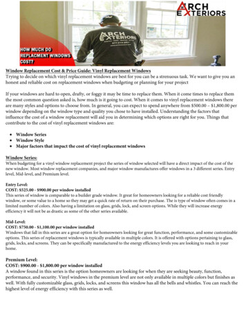
30 CREATING A NEW NAMED VIEW FOR THE CPLANESetting a Dynamic Plane1 Choose Planes, Dynamic planesfrom the Status bar.The Dynamic Planes dialog box andgnomon display in the graphicswindow.The Dynamic Plane function lets you create your own planes using aninteractive gnomon in the graphics window. The gnomon is made up ofthree axes connected at the origin. There are five selection points along eachaxis. Each segment of the axis line is used to produce a different type oftransform motion.WORKING IN THE GRAPHICS WINDOW
SETTING THE CPLANE AND CREATING A NAMED VIEW 31a Axis Origin - Places the origin ofthe gnomon in 3D space.b First Leg - Moves the gnomonalong the selected axis.c Axis Label - Rotates around aperpendicular axis. X axis label rotates around Y Y axis label rotates around X Z axis label rotates around Xd Second Leg - Rotates around theopposite perpendicular axis. X axis label rotates around Z Y axis label rotates around Z Z axis label rotates around Ye Axis Arrowhead - Aligns thegnomon with existing geometry.2 Move the dynamic gnomon to thebottom left corner of the angledface and click once to place thegnomon.WORKING IN THE GRAPHICS WINDOW
32 CREATING A NEW NAMED VIEW FOR THE CPLANE3 Click on the label of the X axis torotate around the Y axis. Do nothold down the mouse button.A dial displays to indicate rotationincrements.TIP: You can change the increments on the dial by pressing the [Ctrl]key and right-clicking. This displays the Gnomon Settings dialog box,where you can adjust alignment and snap increments.WORKING IN THE GRAPHICS WINDOW
SETTING THE CPLANE AND CREATING A NAMED VIEW 334 Rotate the X axis to point at theupper left corner of the angled faceand click once to set the X axisposition.TIP: As you get close to the end ofthe line, the cursor automaticallysnaps to the endpoint and shows aVisual Cue indicating an endpoint.This is part of the AutoCursor functionality. To learn more about AutoCursor, click the Help button on theAutoCursor ribbon bar.5 On the Dynamic Plane dialog box,type AngledFace in the Name fieldand click OK to finish creating thenew view.WORKING IN THE GRAPHICS WINDOW
34 CREATING A NEW NAMED VIEW FOR THE CPLANEIn addition to the brown coordinate axes and origin that display when youpress [F9], Mastercam now displays in blue the Cplane axes and origin forthe new view you defined.Note: Because you created the view from the Planes menu, Mastercamautomatically aligns the Cplane and Tplane with the new view.6 Choose Planes, Named Views from the Status bar.WORKING IN THE GRAPHICS WINDOW
SETTING THE CPLANE AND CREATING A NAMED VIEW 357 Verify that the AngledFace viewappears in the View Selection list.Close the dialog box to completethis exercise.IMPORTANT: If you will not be advancing to the next exercise in thissession, choose File, Save as and save the tutorial part file to a differentfile name, such asANGLEDFACE-MM-YOURINITIALS.MCX-6. Saving the part at this point inthe lesson also saves the new view you created in this exercise. You usethis view in the next exercise.Exercise 4: Creating Geometry in the New NamedViewIn this exercise, you create geometry aligned with the named view, AngledFace.1 If you are continuing from Exercise 3, “Creating a New Named View for theCplane”, skip this step.Otherwise, open the tutorial part file you saved in the previous exercise.2 Choose Planes, Named Views from the Status bar.WORKING IN THE GRAPHICS WINDOW
36 CREATING GEOMETRY IN THE NEW NAMED VIEW3 In the View Selection dialog box,verify that the AngledFace view isselected in the list, and click OK toclose the dialog box.4 Choose Create, Arc, Circle CenterPoint.WORKING IN THE GRAPHICS WINDOW
SETTING THE CPLANE AND CREATING A NAMED VIEW 375 Rotate the Gview slightly (use spin)to get a better view of the singlepoint that displays in the angledface of the part.6 Select the point, and then drag anddraw a circle, clicking again to set itat a size similar to that shown.7 In the Circle Center Point ribbonbar, enter a Radius of 25.0.8 Click OK to accept your newgeometry and exit the Circle CenterPoint function.9 Spin the entities in the graphicswindow to verify that you havedrawn the new circle in the desiredorientation. If it is correctly alignedwith the AngledFace view, you havesuccessfully completed thisexercise.Exercise 5: Introducing the View ManagerThis exercise introduces the View Manager, a central place to see all of the viewssaved in a Mastercam part and their properties. Use the View Manager to create newviews, select different views for each plane, customize their origins, and assign workoffsets.WORKING IN THE GRAPHICS WINDOW
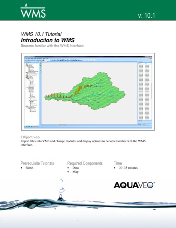
38 INTRODUCING THE VIEW MANAGER1 Choose WCS, View Manager fromthe Status bar.2 Click the Help button on the dialogbox to access the Mastercam Helpfor the View Manager, and use theinformation to experiment with theavailable options. The followingpicture points out some importantareas on the View Manager dialogbox.WORKING IN THE GRAPHICS WINDOW
SETTING THE CPLANE AND CREATING A NAMED VIEW 39.Set Cplanes, Tplanes, and WCS to selected views.Use these functions to create new views.Assign work offsets to views.Set or change the origin of views.WORKING IN THE GRAPHICS WINDOW
40 INTRODUCING THE VIEW MANAGERWORKING IN THE GRAPHICS WINDOW
LESSON 4Using Levels4A Mastercam file can contain separate levels for wireframe, solids, surfaces, draftingentities, toolpaths, and other part data. Organizing your file data by levels lets youcontrol the areas of the drawing that are visible at any time and the entities you canselect in the graphics window.This control makes it easier to work with the file and helps prevent you fromaffecting areas of the drawing you do not want to change.In Mastercam, you can create and name up to 2 billion levels and set any one to bethe main level. The main level is the current working level. For each level you create,you assign a unique number and, optionally, a name. Mastercam’s Level Managerprovides a central location where you view and create levels, and set their properties.
42 LESSON GOALSLesson Goals Open the Level Manager. Turn level displays on and off. Change the main level. Name and assign entities to a level. Move selected entities to a different level using the Status bar Level rightclick option.Exercise 1: Accessing the Level ManagerWhen first opening a Mastercam file, you may not be aware of all entities in the partbecause they may exist on levels that are not displayed in the graphics window. It is agood practice to first access the Level Manager and view all of the levels in the file.In this exercise, you access the Level Manager.1 Open the tutorial part HAIRDRYER-MM.MCX-6.WORKING IN THE GRAPHICS WINDOW
USING LEVELS 432 In the Status bar, left-click on the Level option.TIPS: The number of the current main level displays in the Status bar Levelfield. The tool tip that displays when you hold the mouse over the Levelfield tells you the name of the current main level. (In this example,level 2 is named Wireframe.
Launch Mastercam from the Windows Start menu. 2 Select the default METRIC configuration file: a Select Settings, Configuration, from Mastercam's menu. b Choose .\mcamxm.config Metric from the Currentdrop-down list. c Click OK. 3 From the Mastercam menu bar, choose File, Open. 4 Open ANGLEBLOCK-MM.MCX-6, which was provided with this tutorial.