Transcription
Guides to Good Practicein Corrosion e National Physical Laboratory is operated on behalf of the DTI by NPL Management Limited, a wholly owned subsidiary of Serco Group plc
StressCorrosionCrackingContents1.0 Introductionpage12.0 What causes stress corrosion cracking? 12.12.22.32.4IntroductionActive path dissolutionHydrogen embrittlementFilm-induced cleavage11223.0 When will SCC occur?24.0 Particular problem systems34.14.24.34.44.54.6IntroductionBrass in ammonia-containingenvironmentsChloride cracking of stainless steelSteels in ‘passivating’ environmentsHydrogen embrittlement ofhigh strength steelsHigh strength aluminium alloys334445.0 Environments causing SCC46.0 The effect of electrode potential57.0 Alloy dependence58.0 The effect of stress69.0 Stress corrosion cracking tests710.0 Control of stress corrosion cracking810.110.210.310.4IntroductionSelection and control of materialControl of stressControl of environment888911.0 Living with SCC1012.0 Bibliography11This is an update of a DTI publication first issued in 1982. The new versionhas been prepared by Dr. R. A. Cottis, Corrosion and Protection Centre,UMIST under contract from NPL for the Department of Trade and Industry
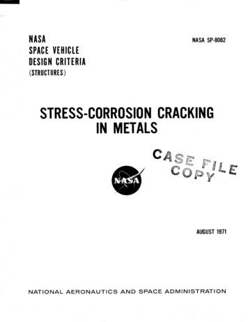
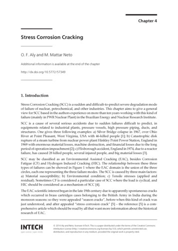
Stress Corrosion Cracking1.0 Introductionhave involved stress corrosion cracking, including the ruptureof high-pressure gas transmission pipes, the explosion ofboilers, and the destruction of power stations and oil refineries.Stress corrosion cracking is cracking due to aprocess involving conjoint corrosion and strainingof a metal due to residual or applied stresses .1Fortunately, the occurrence of SCC depends on theDespite the introduction of polymers and composites in recent.years, metals remain important in structures because oftheir strength, stiffness, toughness and tolerance of hightemperatures.simultaneous achievement of three requirements:a susceptible material,an environment that causes SCC for that material, andsufficient tensile stress to induce SCC.Consequently, SCC is relatively rare, though failures can bevery costly and destructive when they do occur.Unfortunately, metals are subject to corrosion. (The noblemetals, such as gold and platinum are an exception to this,but they are rather too rare for common use). Corrosion cantake many forms; the form that concerns us here is the2.0 What causes stress corrosioncracking?interaction of corrosion and mechanical stress to produce afailure by cracking. This type of failure is known as stresscorrosion cracking, often abbreviated to SCC.2 As will beexplained below, SCC may occur by a number of2.1Introductionmechanisms; when cracking is clearly a result of hydrogenembrittlement, this term may be used in place of SCC.Three basic mechanisms of stress corrosion cracking haveHowever, this distinction is rather arbitrary; we are oftenbeen identified as described below.unsure of the mechanisms of SCC, and many failures that areactually due to the effects of hydrogen would conventionally2.2Active path dissolutionbe ascribed to SCC. Similarly other specific stress corrosioncracking processes have acquired their own names; ‘seasoncracking’ for the cracking of brass in environments containingammonia, ‘caustic cracking’ for the cracking of steel in strongalkalis etc.This process involves accelerated corrosion along a path ofhigher than normal corrosion susceptibility, with the bulk ofthe material typically being passive. The most common activepath is the grain boundary, where segregation of impurityelements can make it marginally more difficult for passivationto occur. For example, when an austenitic stainless steel hasbeen sensitised by precipitation of chromium carbide alongthe grain boundary, the local chromium concentration at thegrain boundary will be reduced, and this region will be slightlyless easily passivated. Consequently, a form of crevicecorrosion can occur, whereby the grain boundary corrodes,with the specimen surface and the crack walls remainingpassive. This process can occur in the absence of stress,giving rise to intergranular corrosion that is uniformlydistributed over the specimen. The effect of the applied stressFigure 1. Aftermath of boiler explosion, probably caused by causticcracking. Picture courtesy of IMechE.is probably mainly to open up the cracks, thereby allowingeasier diffusion of corrosion products away from the crack tipand allowing the crack tip to corrode faster. Active pathSCC is an insidious form of corrosion; it produces a markedloss of mechanical strength with little metal loss; the damagecorrosion of the metal at the crack tip, which limits theis not obvious to casual inspection and the stress corrosionmaximum crack growth rate to around 10-2mm/s, and crackcracks can trigger mechanical fast fracture and catastrophicgrowth rates are often much lower, down to around 10-8 mm/sfailure of components and structures. Several major disasters1 This definition is based on that due to ISO. It may be slightly misleading, in thatthe word ‘straining’ may be taken to imply plastic strain, whereas stress corrosioncracking may occur as a result of elastic strain alone, at least at the macroscopic level.onecorrosion processes are inherently limited by the rate of(about 1 mm in 3 years) or less.2 Other forms of interaction between mechanical stress and a corrosive environmentmay also occur, including corrosion fatigue under the influence of fluctuating stressand corrosion, liquid metal embrittlement and a range of fretting and wear process.These are not considered here: see Shreir et al. (1994) for further coverage of these.The terms “environmentally-assisted fracture” or “environmentally-assisted cracking”are used to cover all of these processes, including SCC.
Stress Corrosion Cracking2.3Hydrogen embrittlement3.0 When will SCC occur?Hydrogen dissolves in all metals to a moderate extent. It is avery small atom, and fits in between the metal atoms in theSCC is not an inevitable process, and for most metals in mostcrystals of the metal.3 Consequently it can diffuse much moreenvironments it will not occur. We can therefore identifyrapidly than larger atoms. For example, the diffusionspecific combinations of metal and environment that arecoefficient for hydrogen in ferritic steel at room temperature issubject to the problem. Unfortunately, of course, as time goessimilar to the diffusion coefficient for salt in water. Hydrogenby we identify more and more such combinations, especiallytends to be attracted to regions of high triaxial tensile stressas engineers strive to use materials more efficiently bywhere the metal structure is dilated. Thus, it is drawn to theincreasing working stresses and using less expensiveregions ahead of cracks or notches that are under stress. Thematerials. Table 1 lists some combinations of metal anddissolved hydrogen then assists in the fracture of the metal,environment that we most commonly associate with SCC.possibly by making cleavage easier or possibly by assisting inthe development of intense local plastic deformation. Theseeffects lead to embrittlement of the metal; cracking may beTable 1. Common SCC systems 4either inter- or transgranular. Crack growth rates are ively rapid, up to 1 mm/s in the most extreme cases.Carbon he bcc (body-centred cubic) crystal structure of ferritic ironCarbonate/lowmoderateIhas relatively small holes between the metal atoms, but thebicarbonatechannels between these holes are relatively wide.Liquid ammonia-lowTCO/CO2/H2O-lowTAerated water-very highTWater-moderateTConsequently, hydrogen has a relatively low solubility inferritic iron, but a relatively high diffusion coefficient.Low Alloy SteelIn contrast the holes in the fcc (face-centred cubic) austenite(e.g. Cr-Mo, Cr-Mo-V)lattice are larger, but the channels between them are smaller,Strong Steelsso materials such as austenitic stainless steel have a higherMhydrogen solubility and a lower diffusion coefficient.Consequently, it usually takes very much longer (years ratherthan days) for austenitic materials to become embrittled byModeWater ( y 1200 MPa)-lowChloride ( y 800 MPa)-lowSulphide ( y 600 MPa)-lowMMhydrogen diffusing in from the surface than it does for ferriticAustenitic Stainless ChloridehighhighTmaterials, and austenitic alloys are often regarded as immuneSteel (including sensitised)Hydroxidehighveryfrom the effects of hydrogen.high2.4MSensitised Austenitic Aerated water-very highIStainless SteellowlowIChloridehighveryFilm-Induced cleavageThiosulphate orpolythionateDuplex Stainless SteelsIf a normally ductile material is coated with a brittle film, thenhighTChloride H2 S high higha crack initiated in that film can propagate into the ductileMartensitic Stainless Chloride (usually H 2 S)moderateTmoderate lowmaterial for a small distance (around 1 m) before beingTarrested by ductile blunting. If the brittle film has been formedSteelsby a corrosion process then it can reform on the blunted crackHigh StrengthWater vapour-lowtip and the process can be repeated. The brittle films that areAluminium AlloysChlorideslowlowIbest-established as causing film-induced cleavage areTitanium AlloysChlorideshighlowTde-alloyed layers (e.g. in brass). The film-induced cleavageMethanol-lowTprocess would normally be expected to give a transgranularN 2 O 4 high-lowTAmmoniacal solutionslowlowfracture.Copper AlloysI(excluding Cu-Ni)3 Technically it is described as an interstitial solute.Tand other nitrogenous4 Table based on original classification due to R C Newman.two
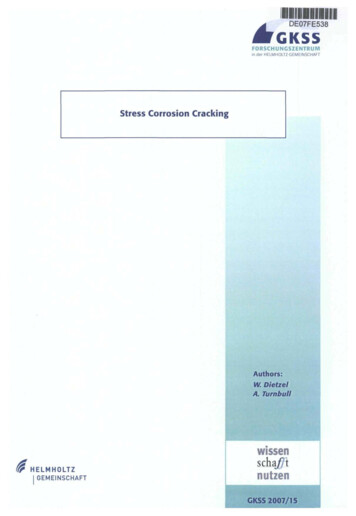
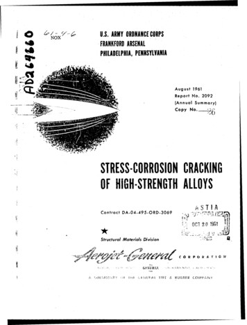
Stress Corrosion Cracking4.0 Particular problem systemsNotes to Table1.2.This Table presents the systems for which SCCproblems are well established and of practicalimportance. The absence of a metal-environmentcombination from this Table does not mean that SCChas not been observed.There are rarely well-defined temperature orconcentration limits for SCC, and the ratings given hereare indicative only. As an approximate guide the termsused equate to the following ranges of values:4.1Table 1 gives an indication of the range of metal-environmentcombination that have given problems, but it is useful toexamine the most common problems in more detail.4.2LowModerateHighVery highConcentrationTemperatureUp to 10-2MUp to 1 MAround 1 MNear saturationAmbientBelow 100 CAround boilingAbove boilingIntroductionBrass in ammonia-containingenvironmentsThis was first experienced (or at least identified) when thebrass cartridge cases used by the British Army in India werefound to suffer from cracking (the ammonia comes from thedecay of organic material). Two explanations have been givenNote that significantly increased local concentrationsmay be obtained under the influence of local boiling orevaporation, or by accumulation in pits and crevices, andcracking is often obtained for nominal concentrationsthat are much lower than is indicated here.for the name applied to it of ‘season cracking’; firstly that itoccurred during the rainy season, and secondly that thecracks resembled the cracks in seasoned wood. It remains aproblem, although the scale is probably reduced because ofthe substitution of plastics for many applications previously3.The fracture mode is classified as intergranular (I)where cracks go along the grain boundaries, transgranular (T) where cracks go across the grains, ormixed (M) where there is a combination of the twomodes, or where the mode can vary depending on theconditions. There are often circumstances that cancause the fracture mode to change (e.g. chloride SCCof sensitised austenitic stainless steel may giveintergranular cracking).dominated by brass. The cracking is intergranular.4.3Chloride cracking of stainless steelAustenitic stainless steels suffer from stress corrosion crackingin hot solutions containing chloride. A high chloride concentrationis required, although relatively small amounts of chloride aresufficient at heated surfaces, where chloride concentration can4.Very high temperature ( 200 C) water environments arevery aggressive, and will cause SCC of a wide range ofmaterials. Expert advice is essential for materialsselection for such conditions.occur, or where chloride is concentrated by pitting or crevicecorrosion, and problems can be experienced in tap water.10-72219 - T37(6.3% Cu)2124 - T851(4.4% Cu)2048 - T851(3.3% Cu)102030-810The requirements for SCC are somewhat different forhydrogen embrittlement than for the other two mechanisms,-910with the only requirement being the availability of a source of-100hydrogen, coupled with a material that is susceptible tohydrogen. The other SCC mechanisms are rather more-1100specific, and normally occur when the metal has a low rate ofgeneral corrosion as a result of a protective surface film, suchas the protective passive oxide film that forms on stainlesssteel.threeStess Intensity / MN m-3/2Figure 2.Intergranularcracking andtransgranularcracking(micrographsand SEMImages)40
Stress Corrosion CrackingThe temperature usually needs to be above 70 C, althoughof routes, including welding, pickling, electroplating, exposureSCCsometo hydrogen-containing gases and corrosion in service.situations, notably more acid solutions. The crackingThe effects of hydrogen introduced into components prior tocontinues at low stresses and commonly occurs as a result ofservice may be reduced by baking for a few hours at aroundcanoccuratlowertemperaturesinresidual stresses from welding or fabrication. The cracking is200 C. this allows some of the hydrogen to diffuse out ofnormally transgranular, although it may switch to anthe steel while another fraction becomes bound to relativelyintergranular path as a result of sensitisation of the steel.harmless sites in the microstructure.4.44.6Steels in ‘passivating’ environmentsHigh strength aluminium alloysCarbon and low alloy steels can suffer from SCC in a wideAluminium alloys are also susceptible to hydrogenrange of environments that tend to form a protectiveembrittlement, although the fcc microstructure means that thepassivating film of oxide or other species. Cracking will nottransport of hydrogen is slower than in high strength steels,normally occur when there is a significant corrosion rate (noteand hence the crack growth rate may be lower. The crackingthat this is not the case for hydrogen embrittlement - seeis normally intergranular. As with steels the susceptibilitybelow). A wide range of environments have been found tobecomes more severe as the strength of the alloy is increased.cause SCC, including strong caustic solutions, phosphates,However, there is also a strong effect of heat treatment andnitrates, carbonates, and hot water. The problems aremicrostructure, and quite high strengths can be obtained withimportant for both economic and safety reasons. Causticgood SCC resistance (as is demonstrated by the use of thesecracking of steam-generating boilers was a serious problemalloys in aircraft construction). Any environments that canin the late 19th century (the necessary strong caustic solutionprovide hydrogen can lead to SCC of susceptible alloys,was produced by evaporation of the very dilute solution insideranging from humid air to salt solution.the boiler as it escaped through leaks in the riveted seams)and boiler explosions led to significant loss of life.More recently gas transmission pipelines have cracked in5.0Environments causing SCCcarbonate solutions produced under protective coatings as aresult of cathodic protection systems. In this case the crackruns along the length of the pipe, and may propagate for veryAs noted above, hydrogen embrittlement processes arelong distances by fast fracture. If the gas cloud that isusually not very strongly influenced by the environment, and allreleased ignites, the resultant fireball is devastating.that is required is conditions that allow hydrogen to be formedby the cathodic corrosion reaction and to enter the steel.4.5Hydrogen embrittlement of highstrength steelsThe two other SCC mechanisms are much more particular,and quite specific environments may be necessary for crackingto occur. This is because cracking depends on the possibilityAll steels are affected by hydrogen, as is evidenced by theof specific corrosion reactions at the crack tip, with otherinfluence of hydrogen on corrosion fatigue crack growth, andreactions occurring on the crack walls and the specimenthe occurrence of hydrogen-induced cracking 5 under thesurface. With only minor changes in the environment one orinfluence of very high hydrogen concentrations. However,other of these requirements may not be met, and cracking willhydrogen embrittlement under static load is only experiencednot occur.in steels of relatively high strength. There is no hard-and-fastlimit for the strength level above which problems will beWhile the requirement for a specific environment is beneficialexperienced, as this will be a function of the amount ofin that it means that SCC is relatively infrequent, it alsohydrogen in the steel, the applied stress, the severity of themakes life difficult for the materials specialist, as it makesstress concentration and the composition and microstructurethe occurrence of fracture rather unpredictable, with subtleof the steel. As a rough guide hydrogen embrittlement isdifferences in service conditions leading to a markedunlikely for modern steels with yield strengths below 600 MPa,difference in behaviour.and is likely to become a major problem above 1000 MPa.The hydrogen may be introduced into the steel by a number5 Hydrogen-induced cracking (HIC) results from the precipitation of hydrogen gas onplanes of weakness in the steel, notably rolled-out sulphide inclusions. It leads tointernal cracks lying parallel to the rolling direction, which appear as blisters whenclose to the surface of the plate. HIC is primarily a problem in the production of souroil (oil containing H2S), as the H2S enhances the entry of hydrogen into the steel.In many situations HIC is relatively non-damaging, as the cracks lie parallel to the planeof the plate, so there is little stress at right angles to the cracks. However, if the crackingis sufficiently severe and the applied stresses high, the cracks may join up to produce afracture, known as ‘Stress-Oriented Hydrogen-Induced Cracking’ or SOHIC.four
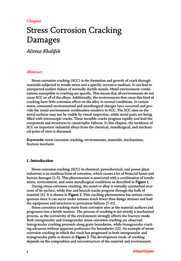
Stress Corrosion Cracking6.0 The effect of electrode potentialThe electrochemical potential of the alloy can have a markedinfluence on the tendency for SCC to occur. For hydrogenwill tend to increase the rate of hydrogen evolution, andthereby the susceptibility to hydrogen embrittlement. It is lessobvious how it happens 6, but more positive potentials thanthe typical free corrosion potential may also increase thePotentialembrittlement of high strength steel a more negative potentialCommonregionsof SCCentry of hydrogen. Figure 3 shows the amount of hydrogenpermeating through a steel membrane as a function of theapplied potential. The SCC of high strength aluminium alloysis also thought to be due to hydrogen embrittlement, but inthis case the dominant effect is the protective nature of thealuminium oxide passive film. As soon as water comes intocontact with metallic aluminium, it will react readily to produceLog Current Densityhydrogen (since aluminium is a very reactive metal).Log Hydrogen Permeation Rate(STD cm3/cm2s)Figure 4. The effect of potential on SCC susceptibility10-510-6Dearated 3N NaCI7.0 Alloy dependenceAerated 3N NaCI10-7The exact alloy composition, microstructure and heat-treatmentcan have a marked effect on SCC performance.10-810-9There are few general rules governing the influence ofDetection Limitmaterial strength on SCC susceptibility. For hydrogenembrittlement processes a higher strength normally increases10-10-1600-1200-800-4000400Applied Potential, mV (SCE)the susceptibility; additionally, higher strength materialsgenerally have a low KIC, and therefore fail by fast fracturewith a smaller SCC crack. Processes that rely on plastic strainFigure 3. The effect of potential on hydrogen entering steel.at the crack tip will be easier for lower strength materials.Hence, many SCC systems, such as caustic cracking ofSCC processes that do not involve hydrogen typically occurcarbon steels, will become more susceptible as the strengthover a limited range of electrode potential. It is often founddecreases.that cracking occurs in the transitional potential regionsbetween active and passive or between passive and pittingQuite small changes to the composition of an alloy can have(Figure 4). In these regions the surface of the component willa marked influence on the SCC behaviour. For examplebe in the passive region, while the crack tip will be in theFigure 5 shows the effect of Cu content on the crack growthactive or pitting state.rate of a series of Al-Cu-Mg alloys. Some care needs to beexercised in interpreting this graph. The change in copperIn service the electrode potential is not usually controlledconcentration of the alloy will have a marked effect on thedirectly, with applied cathodic protection being the maincorrosion behaviour of the alloy (since the copper-containingexample. Rather the potential is determined indirectly by theprecipitates are active cathodic sites), but it will also modifycomposition of the environment, particularly the presence ofthe mechanical properties of the alloy and its response tooxygen and other cathodic reactants. Thus modification of theheat treatment. Consequently, it would probably be possibleoxygen content can often have a profound influence on SCCto change the relative orders of the curves by using differentsusceptibility.heat treatments.6 For an explanation of how the hydrogen is produced, see Chapter 8 in “Corrosion”,by Shreir, Jarman and Burstein. Many early workers assumed that cracking under theinfluence of more positive potentials could not be due to hydrogen, and must, therefore,be evidence for a dissolution mechanism of SCC. We now know that this is not correct,and such arguments should be re-assessed.five
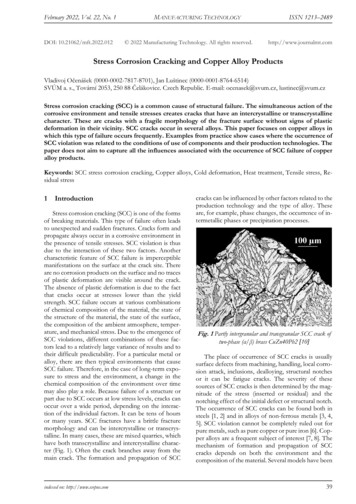
Stress Corrosion Cracking8.0 The effect of stress10-72219 - T37(6.3% Cu)2124 - T851(4.4% Cu)2048 - T851(3.3% Cu)Crack Velocity / m/sOf necessity stress corrosion cracking requires stress, and itis often found that there is a threshold stress below which10-8cracking does not occur (at worst the crack growth rate willbecome so low that failure will not occur in realistic times).For example Figure 6 shows the time to failure of maragingsteel in salt solution. Some care needs to be exercised in the10-9use of such a threshold stress.2400-1110010203040-3/2Stess Intensity / MN mFigure 5. Effect of Cu-content on crack growth rate.Initial Stress / MPa10-1018001200Threshold stress(Did not fail)600The effects of alloying additions are not necessarilyconsistent from one environment to another. Thus, a highermolybdenum content improves the resistance of a low alloysteel to carbonate-bicarbonate cracking, but makes it more0010203040Time to failure / hourssusceptible to caustic cracking.Figure 6. The effect of initial stress on time to failure of maragingsteel in 3.5% NaCI solution.Changes in the thermomechanical treatment of the alloy canchange the sensitivity to SCC, the mode of fracture and eventhe fracture mechanism. To take a specific example,Real components will typically contain defects and designaustenitic stainless steels suffer from SCC in chloridedetails, such as notches, sharp changes in section, welds,solutions. In a correctly heat-treated steel the SCC cracks arecorrosion pits etc, that will produce a stress concentration,transgranular. The mechanism is not fully established;hence allowing the threshold stress to be exceeded locallyfilm-induced cleavage (by way of a de-alloyed layer) iseven though the nominal stress may be well below theprobably the most likely, although all mechanisms remainthreshold. Furthermore, residual stresses produced by weldingplausible.or deformation will frequently be close to the yield stress.If the same alloy is sensitised by a suitable heat treatment,The methods of fracture mechanics 7 provide a means ofthis depletes the grain boundary regions of chromium as aallowing for defects in the structure. Rather than determiningresult of chromium carbide precipitation, and the SCC crackthe time to failure for a specimen exposed to a given stress,path switches to intergranular. The cracking mechanism inthe rate of growth of a pre-existing crack is measured as athis case may change to active path dissolution, although thefunction of the stress intensity factor at the tip of the crack.other mechanisms remain possible.If the same alloy is rolled, a certain amount of strain-inducedmartensite will be formed, and this, combined with thehigher strength of the work-hardened material, leads to asusceptibility to hydrogen embrittlement.7 See “Engineering Materials”, by Ashby and Jones for an excellent introduction tofracture mechanics.six
Stress Corrosion Crackingfactor below KISCC, crack growth, and hence stress corrosion4failure, can be avoided. However, it should be appreciatedthat KISCC is not an invariant material property, and will beaffected by all of the material and environmental factors that2influence other aspects of SCC. Consequently it is importantto be sure that an appropriate value of KISCC is used.-610Crack Velocity / mm/s869.0 Stress corrosion cracking tests4In essence, tests for stress corrosion cracking simply requirethe exposure of the stressed sample of the material or2component in question to the environment of interest. However,there are various classes of test with differing objectives:-710864KISCC2152025303540Stess Intensity Factor / MPa mFigure 7. Relation between crack growth rate and stressintensity factor.This typically results in a graph of the form shown in Figure 7.This exhibits a threshold stress intensity factor below whichstress corrosion cracks will not propagate. This threshold iscommonly given the symbol KISCC, which signifies thethreshold stress intensity factor for stress corrosion crackgrowth in mode I plane strain loading.Once the stress intensity factor exceeds KISCC, the crackgrowth rate increases rapidly, but then reaches a limiting rate,known as the plateau crack growth rate or velocity. As thestress intensity factor is increased further the crack growthrate eventually starts to increase again as the stress intensityfactor approaches the critical stress intensity factor for fastfracture, KIC. In this regime part of the crack growth occurs bypurely mechanical processes, with the environment servingonly to propagate the crack through the toughest regions ofthe microstructure.In principle KISCC provides a good basis for the managementof stress corrosion cracking. By ensuring that the combinationof stress and maximum defect size give a stress intensitysevenStandard tests (see BS, ASTM, ISO and other standardsfor examples) are generally designed to test a materialfor its susceptibility to SCC in an environment that isknown to give problems, or to test components todetermine whether they have the necessarycombination of material properties and residual stressto suffer from cracking. For example, boiling 42%MgCl2 solution is widely used as a test for thesusceptibility of austenitic stainless steels tochloride stress corrosion cracking, and this test may beused to rank alloys or to check components for thepresence of residual stresses.Constant stress or constant displacement testsessentially describe a specimen and a loading methodthat stresses the specimen while exposed to thesolution. The susceptibility to SCC is then assessedby the time taken for failure of the specimen, or thedevelopment of cracks in the surface of the specimen.A common constant displacement test use a U-shapedspecimen, produced by bending a flat plate, and thenstressed by drawing the arms of the U together with aloading bolt (known as a U-bend test).Fracture mechanics tests use a specimen with a preexisting crack (often produced by fatigue cycling).The tests may be evaluated simply by recording the timeto failure, but it is more common to measure the changein length of the crack with time, and thereby derive agraph of crack growth rate as a function of stressintensity factor. With a suitable loading arrangementand specimen geometry it is possible to arrange for thestress intensity factor to fall as the crack grows, andthis provides a useful method of estimating KISCC.The stress corrosion crack is initiated at a relativelyhigh stress intensity factor, but as the crack grows thestress intensity factor falls, until the crack arrests atKISCC.
Stress Corrosion CrackingThe slow strain rate test, or, more accurately, theconstant extension rate test, applies a slow rate ofextension to a specimen. This ensures that there is acontinuing plastic strain at the surface of the specimen,and encourages the initiation and growth of stresscorrosion cracks. The result of the test is evaluated interms of the time taken for failure to occur, theextension at failure or the appearance of the fracturesurface. This test has several advantages, including thelimit to the time taken for the test (mechanical failurewill inevitably occur even if no SCC occurs), and therelatively severe nature of the test, which means that itusually gives conservative results (i.e. failure is unlikelyto occur in service if it does not occur in the test).The slow strain test is normally applied to smoothtensile specimens, although pre-cracked samples mayalso be used.10.2 Selection and control of materialThe first line of defence in controlling stress corrosioncracking is to be aware of the possibility at the design andconstruction stages. By choosing a material that is notsusceptible to SCC in the service environment, and byprocessing and fabricating it correctly, subsequent SCCproblems can be avoided. Unfortunately, it is not
8.0 The effect of stress 6 9.0 Stress corrosion cracking tests 7 10.0 Control of stress corrosion cracking 8 10.1 Introduction 8 10.2 Selection and control of material 8 10.3 Control of stress 8 10.4 Control of environment 9 11.0 Living with SCC 10 12.0 Bibliography 11 Stress Corrosion Cracking This is an update of a DTI publication first .