Transcription
Environmentally-assisted CrackingCorrosion Fatigue andIntroduction to SCCNote: While this course does not contain proprietary BWRVIP or MRP information, per se, it doescontain open literature information that was used in the creation of BWRVIP or MRP documents orBWRVIP or MRP information that was subsequently made non-proprietary via publication, etc.Corrosion and Corrosion Control in LWRs 2011 by SIA, Inc. All rights reserved.
Corrosion Fatigue and SCCLearning Objectives Understand the mechanism of corrosionfatigue vs. mechanical fatigue BWR feedwater nozzleBWR steam dryer bracketsPWR steam generator feedwater nozzle crackingUnderstand the fundamental SCC mechanism Susceptible material, corrosive environmentand tensile stressSCC testingSCC initiation vs. SCC propagationPRS-11-037 F BMG/ 2Corrosion and Corrosion Control in LWRs 2011 by SIA, Inc. All rights reserved.
Specific Forms of Corrosion1. General or uniform corrosion2. Galvanic corrosion3. De-alloying corrosion4. Velocity phenomena - erosion corrosion,cavitation, impingement, fretting and FACMacroLocalizedCorrosion5. Crevice corrosion6. Pitting corrosion7. Intergranular corrosion8. Corrosion fatigueMicroLocalizedCorrosion9. Stress corrosion crackingMechanicalEffectsMicrobiological activity can affect all of the abovePRS-11-037 F BMG/ 3Corrosion and Corrosion Control in LWRs 2011 by SIA, Inc. All rights reserved.
Environmentally-assisted Cracking EAC Corrosion fatigueStress corrosion cracking (SCC) Intergranular stress corrosion cracking (IGSCC)–––––BWR IGSCCPrimary water stress corrosion cracking (PWSCC)Irradiation assisted stress corrosion cracking (IASCC)Interdendritic stress corrosion cracking (IDSCC)Low potential stress corrosion cracking (LPSCC) Transgranular stress corrosion cracking (TGSCC) Criterion for EAC propagation: There is a mechanism to protect the crack sidesIf this is not met, then the incipient sharp crack willdevolve into a blunt notch and will arrestCriterion is readily met in passive alloysPRS-11-037 F BMG/ 4Corrosion and Corrosion Control in LWRs 2011 by SIA, Inc. All rights reserved.
FatigueCorrosion and Corrosion Control in LWRs 2011 by SIA, Inc. All rights reserved.
Mechanical Fatigueand Corrosion Fatigue Fatigue Æ #1 cause of metallic failures Fatigue is the tendency of a metal tofracture under repeated cyclic loading SCC is due to static loading Corrosion fatigue is mechanical fatigueaggravated by corrosion reactions All environments will reduce the fatigue lifeof a component and can eliminate anyfatigue/endurance limit CF is a non-environment specific crackingphenomenon (unlike SCC!)PRS-11-037 F BMG/ 6Corrosion and Corrosion Control in LWRs 2011 by SIA, Inc. All rights reserved.
Example of Mechanical FatigueWhere better to show fatigue due to cyclic stresses than a bicycle!Open UniversityPRS-11-037 F BMG/ 7Corrosion and Corrosion Control in LWRs 2011 by SIA, Inc. All rights reserved.
Mechanical Fatigueand Corrosion Fatigue Cracks formed by CF are usually wider and lessuniform in appearance than mechanical fatiguebecause of the metal removed by corrosion Initiation may occur at multiple sites Microscopically, the cracks are typicallytransgranular following the load,load usually oxide-filledoxide filledand blunt-tipped, with irregular crack profiles andsigns of discontinuous propagation Similar to purely fatigue-driven cracks, orientation isgenerally normal to the predominant stress field However, CF cracks are more likely to form branchesthat follow grain boundaries in the metalPRS-11-037 F BMG/ 8Corrosion and Corrosion Control in LWRs 2011 by SIA, Inc. All rights reserved.
Corrosion Fatigue in LWRs Fatigue is a major consideration where the componentsare subjected to a very large number of cycles (e.g., high–cycle fatigue) and the primary concern is the endurancelimit, i.e., the stress that can be applied an infinite numberof times without failure Cyclic loadings on a LWR component occurs because ofchanges in mechanical and thermal loadings Number of cycles applied during the design life of an LWRseldom exceeds 105 and is low–cycle fatigue Main difference between high–cycle and low–cyclefatigue is that the former involves little or no plasticstrain, whereas the latter involves strains in excess of theyield strain Design curves for low–cycle fatigue are based on tests inwhich strain rather than stress is the controlled variablePRS-11-037 F BMG/ 9Corrosion and Corrosion Control in LWRs 2011 by SIA, Inc. All rights reserved.NUREG-6909, 2/07
CorrosionFatigueMechanismCorrosion and Corrosion Control in LWRs 2011 by SIA, Inc. All rights reserved.
Corrosion Fatigue Mechanism LWR Case Study Examples BWR feedwater nozzleBWR steam dryer support bracketHamaoka 5 ABWR condenser recirc capPWR RCP upper seal cavity pressure sensingline socket weldPRS-11-037 F BMG/ 11Corrosion and Corrosion Control in LWRs 2011 by SIA, Inc. All rights reserved.
Some NRC Corrosion Fatigue Documents BL-88-02 - Rapidly Propagating Fatigue Cracks in SteamGenerator Tubes BL-79-13 - Cracking in Feedwater System Piping BL-79-13 Rev. 2 - Cracking in Feedwater System Piping IN98045 - Cavitation Erosion of Letdown Line Orifices Resultingin Fatigue Cracking of Pipe Welds IN93020 - Thermal Fatigue Cracking of Feedwater Piping toSteam GeneratorsPRS-11-037 F BMG/ 12Corrosion and Corrosion Control in LWRs 2011 by SIA, Inc. All rights reserved.
Some Corrosion Fatigue History World War I – failure of steel wire towing ropes attached toparavane equipment (torpedo-shaped underwater deviceswith serrated teeth) designed to sever mine moorings Tried higher tensile strength wire – no improvement Galvanized original tensile strength wire – worked This was a corrosion problem, not a strength problemCablefailuresPRS-11-037 F BMG/ 13Corrosion and Corrosion Control in LWRs 2011 by SIA, Inc. All rights reserved.
Recommended Corrosion Fatigue FilmNo Highwayin the Sky1951 - Jimmy Stewart andMarlene Dietrich Based on Nevil Shute’s novelNo Highway 1st aircraft disaster film! 1953 – Crash of world's firstpassenger jet (de HavillandComet) due to corrosion fatiguePRS-11-037 F BMG/ 14Corrosion and Corrosion Control in LWRs 2011 by SIA, Inc. All rights reserved.
World Wide Worries OverCorrosion Fatigue!PRS-11-037 F BMG/ 15Corrosion and Corrosion Control in LWRs 2011 by SIA, Inc. All rights reserved.
D. H. Comet 106PRS-11-037 F BMG/ 16Corrosion and Corrosion Control in LWRs 2011 by SIA, Inc. All rights reserved.
D. H. Comet 106 Corrosion Fatigue de Havilland developed/flew the 1st commercial jetaircraft, D. H. Comet 106, in 1949 Several years ahead of rival BoeingCommercial operations in early 1952 Comet crashed shortly after takeoff on May 2, 1953 2 crashes in early 1954 forced British authorities toground the entire fleet Tested fuselage submerged in a tank of water andrepeatedly pressurized and depressurized torepresent repeated flight cycles 1000s cycles, CF cracks were found to be spreadingfrom the square edges of the windows in thepassenger cabinPRS-11-037 F BMG/ 17Corrosion and Corrosion Control in LWRs 2011 by SIA, Inc. All rights reserved.
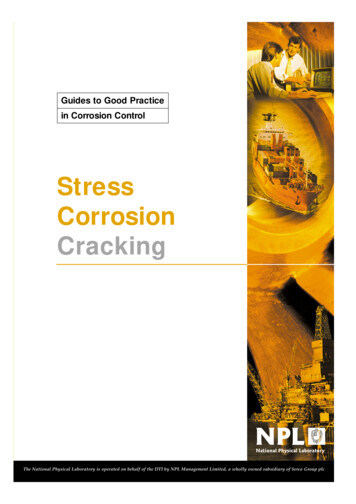
Relationships among SCC, CF and FatigueSCCCFFatigueCyclic StressEnvironmentPRS-11-037 F BMG/ 18Corrosion and Corrosion Control in LWRs 2011 by SIA, Inc. All rights reserved.
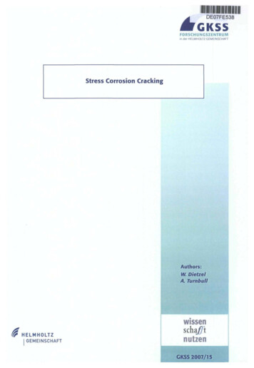
Corrosion Fatigue Reduction of fatigue resistance due to the presence ofa corrosive medium Mechanical fatigue resistance values are nearlyindependent of stress-cycle frequency – allowsaccelerated testingg is greatlygy dependentpbyy stress-cycley Corrosion fatiguefrequency – need time for corrosion reactions –disallows accelerated testing High cycle fatigue crack growth is not strongly influenced byenvironmental effectsLow cycle fatigue crack growth is a strong function ofenvironment Corrosion fatigue cracks are typically transgranular(through the grains) not along gbs. Fracture surfacesmay have striations and oxide particles.PRS-11-037 F BMG/ 19Corrosion and Corrosion Control in LWRs 2011 by SIA, Inc. All rights reserved.
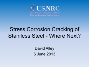
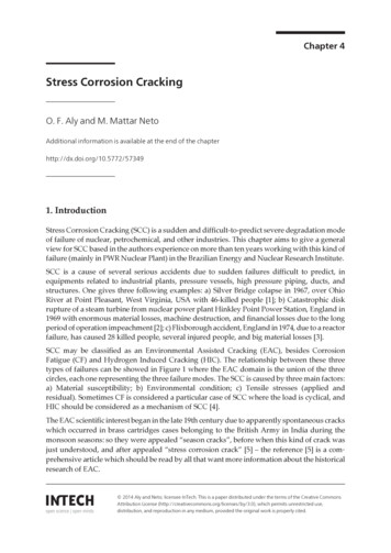
Corrosion FatigueFatigue crack advance occurs by a reversed slipmechanism and the resulting beach marks and striationsare often visibleBeach MarksFatigue data (initiation andgrowth) is cycles-based,but environmental effectsare time-dependent.Thus, problems oftenoccur at low frequencyor strain rate.Cracks are often TG, butif cycling is “gentle,” canbe IGPRS-11-037 F BMG/ 20Corrosion and Corrosion Control in LWRs 2011 by SIA, Inc. All rights reserved.P. Andresen, NRC, 7/06
Corrosion Fatigue Striations withCorrosion ProductsPRS-11-037 F BMG/ 21Corrosion and Corrosion Control in LWRs 2011 by SIA, Inc. All rights reserved.
Corrosion Fatigue - SpatulaCorrosion FatiguePRS-11-037 F BMG/ 22Corrosion and Corrosion Control in LWRs 2011 by SIA, Inc. All rights reserved.
Corrosion Fatigue - MGB DoorNice paint!PRS-11-037 F BMG/ 23Corrosion and Corrosion Control in LWRs 2011 by SIA, Inc. All rights reserved.
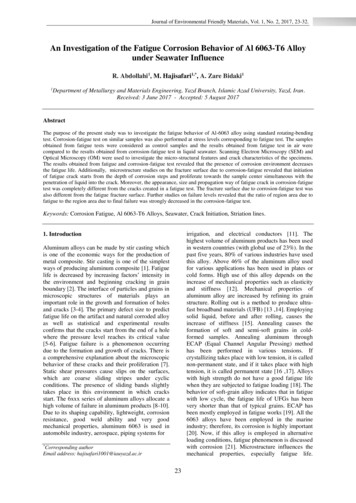
Fatigue and Corrosion Fatigue S-N CurvesWhat would the results of afatigue test in a vacuum look like?Initiation DataFatigue orEndurance LimitStressMechanical FatigueCorrosion Fatigue104105106Number of Cycles to FailurePRS-11-037 F BMG/ 24Corrosion and Corrosion Control in LWRs 2011 by SIA, Inc. All rights reserved.107
Sample Mechanical TheoreticalFatigue S-N Diagram100% Ultimate Tessile Stress9080706050Endurance limit40301.0.E 00 1.0.E 01 1.0.E 02 1.0.E 03 1.0.E 04 1.0.E 05 1.0.E 06 1.0.E 07 1.0.E 08CyclesPRS-11-037 F BMG/ 25Corrosion and Corrosion Control in LWRs 2011 by SIA, Inc. All rights reserved.
Fatigue and Corrosion Fatigue of Steel1200Theoretical 50%UTS ultimate tensile strengthPolished1000Endurance Limmit, 001400UTS, MPaPRS-11-037 F BMG/ 26Corrosion and Corrosion Control in LWRs 2011 by SIA, Inc. All rights reserved.1600180020002200
S-N Fatigue Curve for Type 304 SSASMEPRS-11-037 F BMG/ 27Corrosion and Corrosion Control in LWRs 2011 by SIA, Inc. All rights reserved.
εa- N HWC CF of Type 304 SSNUREG-6909, 2/07PRS-11-037 F BMG/ 28Corrosion and Corrosion Control in LWRs 2011 by SIA, Inc. All rights reserved.
Fatigue MonitoringPressurizerSG #1PumpNo. 1BPumpNo. 1ASG #2PumpNo. 2BReactor PressureVesselPRS-11-037 F BMG/ 29Corrosion and Corrosion Control in LWRs 2011 by SIA, Inc. All rights reserved.PumpNo. 2A
FatiguePro EPRI licensed software Tracks transients (cycles) and fatigue usage for Class 1components Automated cycle counting (ACC) counts and categorizesplant transients into design basis transients based on rawplant instrument data Computes fatigue usage Stress-based fatigue (SBF) computes CF based onstress histories determined from raw plant instrumentdata Cycle-based fatigue (CBF) computes CF based ondesign stress report algorithms and counted plantcycles Rapidly evaluates plant transientsPRS-11-037 F BMG/ 30Corrosion and Corrosion Control in LWRs 2011 by SIA, Inc. All rights reserved.
BWR FeedwaterNozzle CrackingCorrosion and Corrosion Control in LWRs 2011 by SIA, Inc. All rights reserved.
BWR Feedwater Nozzle CrackingLate 1970s – early 1980sNRC as Generic Activity A-10, “BWR NozzleCracking.” Interim guidance was provided inNUREG-0312, which specified augmentedinspections for the nozzle assembly.PRS-11-037 F BMG/ 32Corrosion and Corrosion Control in LWRs 2011 by SIA, Inc. All rights reserved.
Cross Section of BWR Feedwater NozzlePRS-11-037 F BMG/ 33Corrosion and Corrosion Control in LWRs 2011 by SIA, Inc. All rights reserved.
Cause of BWR Feedwater NozzleCorrosion Fatigue Cracking High frequency thermal cycling occurring along thenozzle bore and inner blend radius regions Source of the thermal cycling was the mixing ofrelatively cold feedwater (177-204 C [350-400 F]) withhot reactor water (288 C [550 F]) on the surface ofthe nozzle inner bore The mixing resulted from leakage of the feedwaterinto the annulus region through the gap existingbetween the loose-fitting end of the thermal sleeveand the nozzle safe end Cracks initiated in cladding by high cycle CF Propagation into LAS by low cycle CF - pressure andthermal cycles from start-up/shutdowns andfeedwater on-off transientsPRS-11-037 F BMG/ 34Corrosion and Corrosion Control in LWRs 2011 by SIA, Inc. All rights reserved.
Corrosion Fatigue of BWR RPVFeedwater Nozzle Blend RadiusPhotomacrographPRS-11-037 F BMG/ 35PhotomicrographUnetchedCorrosion and Corrosion Control in LWRs 2011 by SIA, Inc. All rights reserved.PhotomicrographEtched
Corrosion Fatigue Striationsin a Feedwater NozzlePRS-11-037 F BMG/ 36Corrosion and Corrosion Control in LWRs 2011 by SIA, Inc. All rights reserved.
Mitigation of BWR RPV FeedwaterNozzle Cracking Remove nozzle stainless steel cladding Installation of a modified sparger/thermalsleeve arrangement that eliminated theloose fit at the thermal sleeve/safe endinterface Changes to operating procedures and/orfeedwater system modificationsPRS-11-037 F BMG/ 37Corrosion and Corrosion Control in LWRs 2011 by SIA, Inc. All rights reserved.
BWR Triple Thermal SleeveFeedwater Nozzle Design(Low Alloy Steel)(Carbon Steel)Alloy 600PRS-11-037 F BMG/ 38(Alloy 600)Corrosion and Corrosion Control in LWRs 2011 by SIA, Inc. All rights reserved.
Temperature variations w/woBypass LeakagePRS-11-037 F BMG/ 39Corrosion and Corrosion Control in LWRs 2011 by SIA, Inc. All rights reserved.
Steam DryerSupport BracketCCrackingCorrosion and Corrosion Control in LWRs 2011 by SIA, Inc. All rights reserved.
Susquehanna 1 Steam Dryer Support Bracket BWR 4 – February 1985 – 1st refueling outage –184º SDSB Cracks located through the entire Alloy 600bracketof ccrackingac g wasas CCF. SeSeveree e wearea foundou d Cause oon other brackets. Bracket was replaced in 1985, using the samedesign as the original 1985 analysis and subsequent vibration testingfailed to identify source of the fatigue loadingthat caused the CF and severe wearPRS-11-037 F BMG/ 41Corrosion and Corrosion Control in LWRs 2011 by SIA, Inc. All rights reserved.
Susquehanna 1 Steam Dryer Support BracketAlloy600PRS-11-037 F BMG/ 42Corrosion and Corrosion Control in LWRs 2011 by SIA, Inc. All rights reserved.
Susquehanna 1 Steam Dryer Support BracketAlloy 182 Weld PadType 308/309claddingLowAlloySteelRPVCF CrackType 308/309 claddingPRS-11-037 F BMG/ 43RPVAlloy600Corrosion and Corrosion Control in LWRs 2011 by SIA, Inc. All rights reserved.FilletWeldAlloy182Full penetration doublebevel weld
Corrosion Fatigue of Susquehanna 1Steam Dryer Support BracketPhotomicrograph - Transgranular Cracking - UnetchedPRS-11-037 F BMG/ 44Corrosion and Corrosion Control in LWRs 2011 by SIA, Inc. All rights reserved.
Corrosion Fatigue of Susquehanna 1Steam Dryer Support BracketTransgranular crackingNo gross plastic deformationPRS-11-037 F BMG/ 45Corrosion and Corrosion Control in LWRs 2011 by SIA, Inc. All rights reserved.
Corrosion Fatigue of Susquehanna 1Steam Dryer Support Bracket Metallography300x1000xSEM of fracture face near crack tipTransgranular with fatigue striationsSpacing 1 to 4 μmPRS-11-037 F BMG/ 46Corrosion and Corrosion Control in LWRs 2011 by SIA, Inc. All rights reserved.
Cofrentes Steam Dryer Support Bracket BWR 6 – November 1991 - 146º SDSB Crack was located on the inboard top corner ofthe Type 304 SS bracket Most probable cause of cracking was CF from anunknown alternating load, no evidence of SCC Removed segment (to eliminate loose partconcern) showed no evidence of gross plasticdeformation Planar crack surface apparently resulting frompropagation of a crack from a single initiation site Plant operators elected to continue operationwithout any further repair or modificationPRS-11-037 F BMG/ 47Corrosion and Corrosion Control in LWRs 2011 by SIA, Inc. All rights reserved.
Cofrentes Steam Dryer Support BracketsPRS-11-037 F BMG/ 48Corrosion and Corrosion Control in LWRs 2011 by SIA, Inc. All rights reserved.
Kuo Sheng 1 Steam Dryer Support Bracket BWR 6 – October 2001 - 34 and 214º SDSB Cracks located on the inboard corner of theType 304 SS bracket where there were signs ofcontact with the bottom of the steam dryersupport ring Most probable cause of cracking was CF Cracked sections removed to prevent looseparts concern Based on good Cofrentes experience, plantoperators elected to continue operation withoutany further repair or modificationPRS-11-037 F BMG/ 49Corrosion and Corrosion Control in LWRs 2011 by SIA, Inc. All rights reserved.
Kuo Sheng 1 Steam Dryer Support BracketPRS-11-037 F BMG/ 50Corrosion and Corrosion Control in LWRs 2011 by SIA, Inc. All rights reserved.
Nine Mile Point 1 Steam DryerSupport Bracket BWR 2 – March 2011 - 50º, 131º and 230º SDSB 50 1-587A Type 304 SS Left side bottom 25.8 mm (1.015”) raps around thebottom left corner of bracket for 52.8 mm (2.081”)Center bottom 22.2 mm (0.875”) 130 1-587B Typeyp 304 SS 8.9 mm (0.35”) raps around top right corner of bracketextending down right side for 82 mm (3.23”)63.5 mm (2.5“) bottom indication in the base materialacross the entire lug 230º 1-587C Type 304 SS Right side/bracket top 83 mm (3.25”) and transversesaround the top right corner, continues 24 mm (0.93”) Most probable cause of cracking is EACPRS-11-037 F BMG/ 51Corrosion and Corrosion Control in LWRs 2011 by SIA, Inc. All rights reserved.
Schematic of NMP-1 Steam DryerSupport Bracket Configuration63.5mm63.5 mm127 mm50.8mm203mm(Collar)12.7 mmPRS-11-037 F BMG/ 52Corrosion and Corrosion Control in LWRs 2011 by SIA, Inc. All rights reserved.
Nine Mile Point 1 Steam DryerSupport Bracket Design(COLLAR)PRS-11-037 F BMG/ 53Corrosion and Corrosion Control in LWRs 2011 by SIA, Inc. All rights reserved.
NMP- 1 Steam Dryer Support Bracket50º (1-587A) – Left Side Bottom63.5 mmType 304Type 304Alloy 182Alloy 182Saddle52.8 mmPRS-11-037 F BMG/ 54Corrosion and Corrosion Control in LWRs 2011 by SIA, Inc. All rights reserved.
NMP- 1 Steam Dryer Support Bracket50º (1-587A) – Bracket Center BottomType 3041.8 mm22.2 mmSaddleSaddleBottom of Alloy 182 WeldPRS-11-037 F BMG/ 55Corrosion and Corrosion Control in LWRs 2011 by SIA, Inc. All rights reserved.
NMP- 1 Steam Dryer Support Bracket231º (1-587C) – Right SideType 304Type 304Type 304BracketTop83 mm83 mmPRS-11-037 F BMG/ 56BracketSideCorrosion and Corrosion Control in LWRs 2011 by SIA, Inc. All rights reserved.
NMP- 1 Steam Dryer Support Bracket231º (1-587C) – Bracket TopType 304Alloy 182127 mmType 304Type 30424 mmAlloy 182Alloy 182PRS-11-037 F BMG/ 57Corrosion and Corrosion Control in LWRs 2011 by SIA, Inc. All rights reserved.
Hamaoka 5 ABWR CF Damage to 43 Ti condenser tubes in a turbinesteam condenser May 14, 2011 5 tons of seawater enteredreactor following the discovery of 400 tons ofseawater in the condenser, which cools steamfrom the turbine All LPRMs fail a la Millstone 1 in 1972 530 tons/h of seawater were flowing throughthe recirculation pipe Corrosion fatigue of weld on recirc pipe cap?PRS-11-037 F BMG/ 58Corrosion and Corrosion Control in LWRs 2011 by SIA, Inc. All rights reserved.Mainichi Daily News, 6/28/11
Hamaoka 5 ABWR Damage21,000 Titubes3 cm Ø20 cm3.5 kgPRS-11-037 F BMG/ 59Corrosion and Corrosion Control in LWRs 2011 by SIA, Inc. All rights reserved.
Susquehanna 2 New Steam Dryer 15th refuel and inspection outage First cycle of 100%inspection for NEW dryer New dryer was installed to “do the rightthing,” i.e., old dryer was OK Major indications: Dryer seismic ring lug A - through-wallindication in skirt panel 115 mm (4.5”)Dryer lug LL-B 140⁰ - Crack-like indication ondryer lower bracket to lifting lug weld 13 mm( 0.5”)PRS-11-037 F BMG/ 60Corrosion and Corrosion Control in LWRs 2011 by SIA, Inc. All rights reserved.E. Camacho, BWRVIP, 6/11
Susquehanna 2 New Steam DryerIndicationrunningthrough thedryer skirtpanel to midring 0⁰ weld(th(through-wall)hll)E. Camacho, BWRVIP, 6/11PRS-11-037 F BMG/ 61Corrosion and Corrosion Control in LWRs 2011 by SIA, Inc. All rights reserved.
Susquehanna 2 New Steam Dryer4 indication areasMultiple IGSCC indications (4 areas) in dryer skirt weld 135⁰Most prominent cracks are 13 mm (0.5”)- shallow depthPRS-11-037 F BMG/ 62Corrosion and Corrosion Control in LWRs 2011 by SIA, Inc. All rights reserved.E. Camacho, BWRVIP, 6/11
RCP Upper SealCavity PressureSensing Line SocketWeld FailureCorrosion and Corrosion Control in LWRs 2011 by SIA, Inc. All rights reserved.
RCP Socket Weld Failure RCS pressureboundary leakage 19 mm (¾”) flange topipe socket weld Schedule 160, Type304 SS pressuresensing line First field flangeconnection off sealpackage NOT 54ºC (130ºF) NOP 5.5 MPa (800psig)PRS-11-037 F BMG/ 64Corrosion and Corrosion Control in LWRs 2011 by SIA, Inc. All rights reserved.
Close Up of LeakEnvironment: 837 ppb Cl! 626 ppb SO4! 27 ppb F Nominal valuesall 50 ppbPRS-11-037 F BMG/ 65Corrosion and Corrosion Control in LWRs 2011 by SIA, Inc. All rights reserved.
RCP Socket Weld Failure At OD surface,crack locatedentirely withinweld metal Crack extended 120o aroundcircumference No gross plasticdeformationevident120ºPRS-11-037 F BMG/ 66Corrosion and Corrosion Control in LWRs 2011 by SIA, Inc. All rights reserved.
RCP Socket Weld FailureCircumferentialcrackPRS-11-037 F BMG/ 67Corrosion and Corrosion Control in LWRs 2011 by SIA, Inc. All rights reserved.
RCP Socket Weld FailurePipeWeldSocket base metalPRS-11-037 F BMG/ 68 Radial sectionopposite fracture Good quality weld Weld dimensionsexceeded Coderequirements No evidence ofinadequate pullbackClose up next slideCorrosion and Corrosion Control in LWRs 2011 by SIA, Inc. All rights reserved.
RCP Socket Weld FailureWeldPipeFlange Multiple, minimallybranched cracks inweld metal and pipe Transgranular crackpath in Type 304 SSpipe base material No evidence ofsensitization No cracking observedin Type 316 SS flangebase metalStress concentrationPRS-11-037 F BMG/ 69Corrosion and Corrosion Control in LWRs 2011 by SIA, Inc. All rights reserved.
RCP Socket Weld FailureStriations evident on portions of leak path fracture surfacePRS-11-037 F BMG/ 70Corrosion and Corrosion Control in LWRs 2011 by SIA, Inc. All rights reserved.
RCP Socket Weld Failure Observations suggest: Environmentally assisted crackingCausative loads are cyclic in natureStagnant, oxygenated RCS likely a key factorSServicei lifelif suggestt ffailureilmechanismh iisiage relatedPRS-11-037 F BMG/ 71Corrosion and Corrosion Control in LWRs 2011 by SIA, Inc. All rights reserved.
Introduction toStress CorrosionCrackingCorrosion and Corrosion Control in LWRs 2011 by SIA, Inc. All rights reserved.
The Poetry of SCCOn Stress Corrosion (Abridged Version)S. P. Rideout, Savannah River LaboratoryThe image of stress corrosion I seeIs that of a huge unwanted tree,Against whose trunk we chop and chop,But which outgrows the chips that drop;At intervals researches gather,And on mechanisms all palaver;Each to his own work will refer,Ignoring those who don’t concur.And from each gash made in its barkA new branch grows to make more darkThe shade of ignorance around its base,Where scientists toil with puzzled face.But as we speculate and ponder,Those who run the mills out yonderTo us with anxious voices wail,“Please help us lengthen ‘time to fail!’”Chemists and metallographers,Technicians and philosophers,Through struggling individuallyTheir common goal: to fell the treePRS-11-037 F BMG/ 73Corrosion and Corrosion Control in LWRs 2011 by SIA, Inc. All rights reserved.
Stress Corrosion Cracking Ultimate in localized corrosion! Cracks that create the impression of inherentbrittleness, but it is corrosion! Bulk alloy retains its typical ductility values All alloys are susceptible to SCC in at least oneenvironment Pure metals are very resistant.environment.resistant SCC does not occur in all environments An environment that induces SCC in one alloydoes not necessarily induce SCC in another alloy Environmentally specific cracking (unlike mostcorrosion fatigue) Complex since SCC involves many technicaldisciplines, variables and interdependenciesPRS-11-037 F BMG/ 74Corrosion and Corrosion Control in LWRs 2011 by SIA, Inc. All rights reserved.
BWR Example of SCC Mitigationwith Pure Metals Pellet cladding interaction (PCI) SCC due to corrosive fission products andcladding tensile stress from pellet expansion Solution: pure Zr barrier interior cladding by coextrusion with 37 F BMG/ 75Corrosion and Corrosion Control in LWRs 2011 by SIA, Inc. All rights reserved.
SCC in LWRs SCC is the most virulent of degradationprocesses in LWRs and is likely to continue SCC is not easily detected SCC affects the integrity of the most criticalcomponents SCC is a precursor to subsequentlydangerous although low probabilityphenomena Break before leak (BBL), not LBBLoss of coolant accident (LOCA)R. Staehle, QMN, 6/10PRS-11-037 F BMG/ 76Corrosion and Corrosion Control in LWRs 2011 by SIA, Inc. All rights reserved.
SCC MechanismCorrosion and Corrosion Control in LWRs 2011 by SIA, Inc. All rights reserved.
Stress Corrosion Cracking There are three necessary fundamentalparameters that must be simultaneouslypresent for SCC: Tensile stress (total of all stresses, i.e., applied,residual etc.)residual,etc )“Corrosive” environmentSusceptible material If anyone of these three necessaryfundamental parameters is absent or reducedbelow some “threshold” value, SCC cannotoccurPRS-11-037 F BMG/ 78Corrosion and Corrosion Control in LWRs 2011 by SIA, Inc. All rights reserved.
Tensile Test Most fundamental type of mechanical properties test Tensile tests determine how the material will react toforces being applied in tension, i.e., its strength andelongation (ductility) via a stress strain plot Initially the relationship between the applied loadand the elongation is linear “Hooke's Law" where the ratio of stress (σ) to strain (ε) isa constant E (Young’s Modulus), σ/ε E Yield strength (YS) stress applied to the materialat which plastic deformation starts to occurSince departure from the linear elastic region is noteasily identified, the ASTM E8 0.2% offset methodis used to determine the offset YS (proof stress)PRS-11-037 F BMG/ 79Corrosion and Corrosion Control in LWRs 2011 by SIA, Inc. All rights reserved.
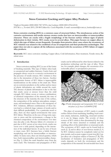
Engineering SStress (σ)Engineering Stress Strain Curve0.2% Offset ractureStrengthOffset Yield StrengthProportionality limitUniform formPlasticDeformation(Necking)Tensile Specimens0.2%PRS-11-037 F BMG/ 80Engineering Strain (ε)Corrosion and Corrosion Control in LWRs 2011 by SIA, Inc. All rights reserved.Fracture
Engineering Stress Strain CurveClose UpProportionality limitOffset Yield StrengthYoung’s ModulusE σ/εPRS-11-037 F BMG/ 81Corrosion and Corrosion Control in LWRs 2011 by SIA, Inc. All rights reserved.
Engineering vs. “True”Stress Strain CurvesEngineeringσe P/A0εe (L-L0)/L0“True” Stress StrainStresss (σ)FractureStrengthEngineeringStress Strain“True”σt P/ALfεt Lo dL / L ln(L/L0)Engineering stress and engineering strain are calculatedbased on the original dimensions of the specimen and not theinstantaneous values as is the case for “true” stress and strainStrain (ε)PRS-11-037 F BMG/ 82Corrosion and Corrosion Control in LWRs 2011 by SIA, Inc. All rights reserved.
Tensile Testing EquipmentResistanceheatedPRS-11-037 F BMG/ 83Corrosion and Corrosion Control in LWRs 2011 by SIA, Inc. All rights reserved.
Example of Tensile Test ResultsAs-received copper specimenNeckingPost-tensile test copper specimenPRS-11-037 F BMG/ 84Corrosion and Corrosion Control in LWRs 2011 by SIA, Inc. All rights reserved.
Cup Cone Fracture Surface - AluminumCupPRS-11-037 F BMG/ 85ConeCorrosion and Corrosion Control in LWRs 2011 by SIA, Inc. All rights reserved.
Ductile vs. SCC FailuresA0Ductile Failures High % reduction in area (necking) High % elongationA Dimpled fracture surfaceSCCA0 0% reduction in area 0% elongation IG/TG fracture surfacePRS-11-037 F BMG/ 86Corrosion and Corrosion Control in LWRs 2011 by SIA, Inc. All rights reserved.
Ductile vs. SCC FailuresWow!NUREG-6892, 1/06PRS-11-037 F BMG/ 87Corrosion and Corrosion Control in LWRs 2011 by SIA, Inc. All rights reserved.
SCC Fundamental ParametersTensileStressSusceptibleMaterialSCCVenn Diagram“Corrosive”EnvironmentPRS-11-037 F BMG/ 88Corrosion and Corrosion Control in LWRs 2011 by SIA, Inc. All rights reserved.
Some SCC History – “Caustic Embrittlement” 19th and 20thcentury rivetedcarbon steelsteam boilersexplode Cracks aroundrivet holes Susceptible areascold worked byriveting NaOH fromchemicaltreatment of boilerwater – CausticSCCca 1850 Due to local deposition of concentrated OH- at 200 to 250oCPRS-11-037 F BMG/ 89Corrosion and Corrosion Control in LWRs 2011 by SIA, Inc. All rights reserved.
Some SCC History – “Remember the Maine!”1898Remember the SCC!1st war started by SCC!PRS-11-037 F BMG/ 90Corrosion and Corrosion Control in LWRs 2011 by SIA, Inc. All rights reserved.
SCC Parameters and Mitigationfor “Caustic Embrittlement”Anneal outresidualstress/coldwork afterrivetingChange thealloyHigh residualtensile stressfrom rivetingCarbon steelSCCHigh temperaturewater with NaOHReplace NaOH incoolant or add Na2HPO4PRS-11-037 F BMG/ 91Corrosion and Corrosion Control in LWRs 2011 by SIA, Inc. All rights reserved.
Some SCC History – “Season Cracking” British colonial times in India(1920s) Small arms brass cartridgesde
Environmentally-assisted Cracking EAC Corrosion fatigue Stress corrosion cracking (SCC) Intergranular stress corrosion cracking (IGSCC) - BWR IGSCC - Primary water stress corrosion cracking (PWSCC) Irradiation assisted stress corrosion cracking (IASCC) Corrosion and Corrosion Control in LWRs