Transcription
Bulletin A102-1 Brasch Manufacturing Co., Inc.
IndexBottom Insert . . . . . . . . . . . . . . . . . . . . 11Raintight Construction . . . . . . . . . . . . . . 11Bottom Outlet . . . . . . . . . . . . . . . . . . . . 12Recessed Terminal Box. . . . . . . . . . . . . . 10Construction Details . . . . . . . . . . . . . . . 6, 7Round-Duct Construction . . . . . . . . . . . . 14Dusttight Heaters . . . . . . . . . . . . . . . . . . 10SCRs . . . . . . . . . . . . . . . . . . . . . . . . . . . 8Express Duct Heaters . . . . . . . . . . . . . . . 27SCR-Vernier . . . . . . . . . . . . . . . . . . . . . . 8Finned Tubular Construction . . . . . . . . . . 15Single Zone. . . . . . . . . . . . . . . . . . . . . . 16Flanged Construction . . . . . . . . . . . . . . . . 5Sizes and KW Ratings . . . . . . . . . . . . . . . 3Installation . . . . . . . . . . . . . . . . . . . . . . . 5Slip-in Construction . . . . . . . . . . . . . . . . . 5Insulated Terminal Box . . . . . . . . . . . . . . 12Specification, Sample . . . . . . . . . . . . . . . . 4Multizone . . . . . . . . . . . . . . . . . . . . . . . 16Step Controllers. . . . . . . . . . . . . . . . . . . . 8NEC Requirements . . . . . . . . . . . . . . 24-26Technical Data. . . . . . . . . . . . . . . . . . . . 16Oven Heaters . . . . . . . . . . . . . . . . . . . . 13Thermostats . . . . . . . . . . . . . . . . . . . . . . 9Pressure Drop Graph . . . . . . . . . . . . . . . 18Wiring Diagrams-Control Systems. . . . 20-23Protective Screens . . . . . . . . . . . . . . . . . 13UL . . . . . . . . . . . . . . . . . . . . . . . . . . . . . 3Quality Control. . . . . . . . . . . . . . . . . . . . . 32BRASCH MANUFACTURING
Ratingsand SizesUL ListingYou specify it—we build it! Heatersfor zero clearance between heater and combustible surfaces. Listing includes alldescribed in this bulletin are custombuilt-in components unless otherwise noted. Heaters are also UL Listed for usedesigned at no extra charge to yourwith heat pumps and air conditioners when mounted 4 feet or more from unit andexact size, wattage, voltage andmaximum inlet air temperature is 100 F.UL Listed by Underwriters Laboratories, Inc. under File Nos. E 39836 and E39386phase and number of steps. Any ductsize from W 5" and H 4" minimum to W 480" and H 180"maximum, wattages to 2000 KW canbe furnished. Base price dependsQuality Controlupon duct size and KW rating; baseprice is the same for single or threeHeaters are dielectrically tested for 1000V plus twice the rated voltage or 2000V,phase and does not change withwhichever is higher. The resistance of each heater is measured and recorded andnumber of steps.must be within 5% of rated value. Electrical components are tested and inspected after installation in the heater. Every heater is checked twice; once in produc-For practical design of heater, mini-tion and once by a trained Quality Control inspector who gives each heater a thor-mum recommended KW per step is .5ough inspection.KW for 208V single phase; 1.0 KW for277V or 480V single phase and 2.0KW for 480V or 600V three phase.Suggested Schedule for Electric Heating CoilsTagNO.InsideDuctSizeW' x H'CFM(Min.)KWEH-1 to 1012 x 8430EH-1118 x 12AH-1—BULLETIN A102-1Voltage/PhaseNo. .5480/3124SCR500085.0480/3624Step ControlHorizontalorVerticalAirflowDirectionSpecial FeaturesDirect ActingHAFDirect Acting TransducerPreheat for Carrier 39BA120-B3
Sample Specification-Open Coil - Finned TubularGeneral: Electric duct heaters and air handling coils shall be as manufactured byBrasch Manufacturing Company, Inc. Voltage, size, KW, steps and control voltageshall be as scheduled. Three phase heaters shall have balanced phases.1.Heaters shall be UL Listed for zero clearance an shall meet all NEC requirements.2.Type: Heaters shall be of the following configuration:For Duct Mounting . . . . . . . . . . . . . . . . . . All Slip-in or FlangedFor Air Handling Unit Coils . . . . . . . . . . . . All Slip-in or FlangedMultizone Hot Deck Coils . . . . . . . . . . . . . . . . . . . . Slip-in TypeSPECIAL CONSTRUCTION Insulated Terminal Box Dusttight Terminal Box Raintight Construction (nonremovable flange) Bottom Insert - open coil only Round-duct Construction Stainless Steel Frame Aluminized Steel Frame Protective ScreensA. Inlet Side OnlyB. Outlet Side OnlyC. Both Sides3.Open coil heating elements shall be 80% nickel and 20% chromium; stepsshall be arranged to prevent stratification when operating at less than fullcapacity. Elements for draw-through air handling units shall be derated to35 watts per square inch; blow-through air handling coils and variable volume reheat coils shall be derated to 25 watts per square inch.OVERCURRENT PROTECTION Automatic Circuit Breakers (in lieu of fuses) Fuses Per Step (in lieu of one per 48 amperes) Main Supply Overcurrent Protection (heaters 48 amperes or less)4.Element terminals shall be stainless steel; insulators and bracket bushingsshall be nonporous ceramic and securely positioned. Terminals shall bemachine crimped to elements.OVERTEMPERATURE PROTECTION Manual Reset Thermal Cutout in control circuit in series with automatic Manual Reset Thermal Cutout in power lines (in lieu of secondary cutouts) Manual Reset Thermal Cutout operating back-up contactors5.Elements for Finned Tubular heaters shall have steel fins brazed to copperplated sheath. Element wire shall be 80/20 Nichrome. Elements shall beprotected against corrosion by a high-temperature aluminum coating.Terminals shall be sealed with silicone rubber to protect against moisture.6.Frame shall be constructed of heavy gauge galvanized steel with galvanizedsteel brackets, stiffening ribs and gussets spot welded to the frame.7.Terminal box shall be spot welded construction with solid, hinged cover,totally enclosed, without louvers or grilles per the UL Standard.8.Recessed terminal box to be provided when coils are installed in ducts withinternal insulation or obstruction greater than 1".9.Direction of airflow: heaters shall be interchangeable for horizontal left orright or vertical up airflow except when position sensitive mercury contactors or SCRs are built-in. In these cases, airflow direction shall be as scheduled.10. Safety devices: a disc-type automatic reset thermal cutout shall be furnished for primary overtemperature protection. For secondary protection, asufficient number of replaceable thermal cutouts in the power lines shallde-energize elements if the primary cutout fails. All safety devices shall beserviceable through the terminal box without removing the heater from theduct.11. Wiring diagrams: a unique wiring diagram shall be furnished for eachheater. Diagram shall include recommended supply wire gauges per NECand fuse sizes. Typical wiring diagrams are not acceptable.12. Built-in components shall include safety interlocking disconnect switch, disconnecting break magnetic contactors, transformer with primary fusing perUL, pressure-type airflow switch set at .05" WC, supplementary circuit fusesper NEC (one set of fuses per 48 amp circuit), and separate load and control terminal blocks to accept conductors as shown on the electrical plan.SWITCHING DEVICES AND CONTROLS Magnetic Contactors, De-energizing (in lieu of disconnecting) Mercury Contactors (sealed for quiet switching)A. Disconnecting BreakB. De-energizing Break SCRs (solid state modulating control) Toggle Switch(es)A. One Per StepB. Interrupts Control Voltage Door Interlock Switch (to break control circuit) Step Controller(s) (specify input)A. Electronic Modulating Time Delay Relay PE Switch(es) (for pneumatic control; specify close or open on pressure rise) Transducer (pneumatic to 135 Ohm) Pilot Light(s)A. One Per Step ( x # of steps)B. Control Voltage OnC. Power On (Line Volts)D. Normal Operation (Automatic Reset Circuit is Closed)E. Airflow Switch OpenF. Manual Reset Thermal Cutout OnG. Push-To-Test Type (Not UL except with 16E)J. Overtemperature (Automatic Reset Cutout Circuit is Open)K. Nema - 12 or Nema - 4L. Heater On14. Manufacturer to provide two year limited warranty for heating elements;other components and accessories to be warranted for one year.13. Special features: the following special features are required as scheduled:4BRASCH MANUFACTURING
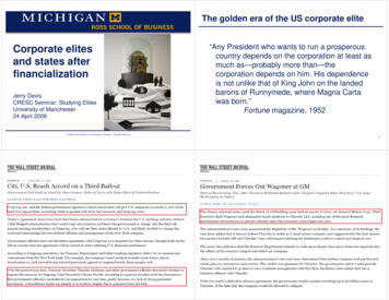
TypesFigure 2A Flanged HeaterFigure 1A Slip-in HeaterSLIP-IN HEATER—standard and by far the most widely used becauseof the ease of installation; see 1A and 1B. When built-in controls arespecified in a slip-in heater, they are usually mounted in the left-handoverhang (S dimension in Figure 1B). If right-hand overhang is desired,specify S dimension to be 1", T dimension as required.FLANGED HEATER—(optional) consists of a slip-in heater mounted in aflanged duct section; see Figures 2A and 2B. The slip-in portion slides outwithout removing flanges from duct. When built-in controls are specified ina flanged heater, they are mounted in the terminal box of the slip-in portion;the frame containing the elements stays the same. The flanged duct section is increased in depth to accommodate the larger terminal box.DimensionsFigure 1BFigure 2BH 4" minimum, 180" maximum; W 5" minimum, 480" maximum (for sizes over H 90" or W 120", consult factory). E, F, S, T, Y and G dimensions depend on KW, voltage, phase, number of steps and built-in controls; consult factory.InstallationBulletin I-17 or I-556-1 is included with each heater. Covers maintenance and installation warnings on how NOT to install duct heaters. Service instructions also given.Figure 1CFigure 1C SLIP-IN HEATERStep 1. Cut hole in side of duct 1/8" larger than heater body.Step 2. Insert heater until terminal box covers opening.Step 3. Secure heater in place with sheet metal screws.BULLETIN A102-1Figure 2CFigure 2C FLANGED HEATERStep 1. Provide flanges on ends of duct matching heater flangesStep 2. Secure heater flanges to duct flanges with sheet metal screws,so that mounting screws do not enter terminal box.5
Automatic reset thermal cutout (primarysafety protection) standard on everyheater. Automatically resets after heaterhas cooled. Wired in series with elements on single phase heaters notexceeding the ratings. For all otherheaters cutout controls contactors.Construction DetailsManual reset thermal cutout(optional) secondary safety protection. External reset button isnormally located in terminalbox cover.NOTE:Central location of thermal cutout allows sameheater to be used for left- or right-hand and verticalup airflow.Main supply terminals for connection to copper supply wires(standard).Built-in transformer provides control voltage ifnot same as line voltage.(Optional)Properly sizedknockoutsGround lugControl terminalsReset button for manual reset thermal cutout.(Optional)Built-in fuses.(Optional)Built-in magnetic contactor. (Optional)Terminal box cover is solid, nonperforated type,assuring dust-free, trouble-free operation ofbuilt-in contactors. Screws are accessible fromfront. Hinged cover provided when fuses, PEswitches, or interlocking disconnect switch arebuilt-in. (Cover shown separate here for clarity)6Heavy gauge corrosion protected terminalbox (galvanized steel standard)Figure 1Typical Slip-in Heater (Featuresalso apply to flanged heaters)BRASCH MANUFACTURING
Open coil iron-free heating elements. Highest grade (80%nickel, 20% chromium) Type A resistance wire has longer life;coils do not sag or oxidize; resistance does not change withtime; glowing is minimized with sufficient airflow. Elementsare spread across the face of the heater, when practical, toavoid stratification.Optional finned tubular heating elements. 80/20 nickel/chromium innercoil centered in copper-plated steeltubes; magnesium oxide filler assuresrapid heat transfer from coil to steelfins brazed to tube; silicone rubberdouble seals prevent magnesium oxidecontamination. High temperature aluminum coating protects element surfaces from corrosion.Secondary disc-type cutouts standard on every heater. Set athigher temperature than automatic reset thermal cutout. MeetsUL and NEC requirements. Sufficient number of cutouts locatedin the power lines de-energize elements should automatic resetthermal cutout fail; easily serviced through the terminal box. Noback-up contactors are required.Support brackets with special reinforcements (ribbing along edges and gussetsin top and bottom mounting flanges)Coil terminations have been designedto assure trouble-free connections.Ceramic bushings and stainless steelterminals guard against high temperatures. Coil connection is machinecrimped and nuts are tightened tospecified torque.BULLETIN A102-17
Step ControllersStep controllers are used to control multi-step heaters.ELECTRONIC MODULATINGSolid state electronic step controllers will switch up to tencontactor holding coils each and may be wired in series fora maximum of 30 steps. They are available with a singleinput from all commonly used thermostat input signals.The step controller automatically recycles to the full-offposition in case of a power interruption.SCRsSCR VernierSilicone controlled rectifiers (SCRs) are used to provide very close heat controland/or silent operation for critical areas such as laboratories, computer rooms andexecutive offices. They are a solid state device with no moving parts which willprovide 100% stepless and noiseless modulation through many years of troublefree service. The SCR has heat sink mounted protruding through the terminal boxto maximize convection cooling. The heat sink is electrically insulated from liveparts. Power and heat output are precisely controlled from zero to 100% in directresponse to the modulating thermostat signal (figure 25). All commonly used thermostat input signals will be accepted by the SCR without a special interface. Asafety contactor must be used.SCR Vernier systems are used on larger KW heaters where very close heat control is required. The SCR Vernier system employs a combination of SCR and nonSCR steps. For electric/electronic controls, a step controller energizes the nonSCR steps; for pneumatic controls, adjustable differential PE switches energizethe non-SCR steps. The system is more economical for larger KW heaters thanfull SCR control while providing the same very close heat control as the full SCRsystem. This is accomplished by satisfying most of the heat requirement throughthe non-SCR steps and then the last portion of the heat requirement is "finetuned" by the modulating SCR controller. The SCR step is nominally equal to theKW of a non-SCR step to provide an even transition between steps.All elements in the heater are simultaneously controlled, thus avoiding problemsof air stratification. Zero angle firing interrupts the full wave AC cycle only whencurrent passes through zero, minimizing radio frequency interference.8BRASCH MANUFACTURING
ThermostatsTable 23: ThermostatsCatalogNumberTypeTemp. RangeRatingsActionNo. StepsT-101Room40 - 90 F120 - 240VPilot1T-102Room40 - 90 F120 - 240VPilot2T-111Room40 - 90 F24VPilot1T-112Room40 - 90 F24VPilot2T-201Room40 - 90 F120 - 277VLine1T-300Room60 - 90 FD.C./Resistive OutputStep ControllerMod.C1025Room60 - 90 FD.C./Resistive OutputSCRMod.T-400Room40 - 90 FPneumaticDirect ActingMod.T-401Room40 -90 FPneumaticReverse ActingMod.T-601Duct60 -90 F120 - 240VPilot1T-602Duct60 - 90 F24 - 240VPilot2T-603Duct60 - 90 F24 - 277VPilot3T-604Duct60 - 90 F120 - 277VPilot4T-810Duct80 - 100 FD.C./Resistive OutputStep ControllerMod.T-100-M043Duct0 - 180 FD.C./Resistive OutputSCRMod.TG-100MThermostat Guard————NOTE: Data subject to change without notice.BULLETIN A102-19
Special ConstructionsHeaters forDucts withInternalObstructionsRECESSED TERMINAL BOX—forslip-in heaters; brings element terminals and thermal cutouts further intothe airstream (recommended wherethe element terminals are blocked byan obstruction of more than 1").DUSTTIGHT TERMINAL BOX—slip-in orflanged heaters have sturdy terminal box andcover with sealed seams. A gasket is providedinside the terminal box cover to seal the cover tothe terminal box. UL Listed for indoor use only.10BRASCH MANUFACTURING
Bottom TerminalBoxesBOTTOM INSERT—slip-in heater inserts througha hole in the bottom of a horizontal duct. Internalterminal box contains resistance coil terminations,automatic reset and secondary thermal cutouts, allprewired to terminal blocks in field terminal box.Control components such as contractors, fusesand transformers are mounted in bottom terminalbox. Specify W and H dimensions (minimum Wdimension is 12").RAINTIGHT HEATER—UL Listed for outdooruse; formed of heavy gauge galvanized steel,sealed with high temperature sealant. May besupplied with recessed construction. Flangedconstruction fits any horizontal, rectangular duct.Available with standard built-in components thatdo not protrude through door such as contactors,fuses, transformers, step controller, PE switches,etc. Insulated terminal box or insulated flange arenot available UL Listed. Consult local representative for additional information. Not suitable for usein salt spray environments.BULLETIN A102-111
Special Constructions (cont.)BOTTOM OUTLET—recommended wherea flanged heater is desired with field terminal box at the bottom of the horizontal duct.Internal terminal box contains resistancecoil terminations, automatic reset thermalcutout and secondary thermal cutouts, allprewired to terminal blocks in field terminalbox. Control components such as contactors, fuses and transformers are mountedin bottom terminal box. Not available withbuilt-in weather resistant or dusttight terminal box.INSULATED TERMINAL BOX—recommended whenever heaters are used in airconditioning ducts in areas with high relative humidity. Slip-in or flanged heaters withinsulated terminal box have insulatingboard fastened to the back of the terminalbox, between the duct and the terminal box.12BRASCH MANUFACTURING
PROTECTIVE SCREENS—prevent accidental contact and possible electrical shock,especially where maintenance personnel arelikely to enter the duct near the heater.Galvanized 1/2" x 1/2" hardware cloth meshis standard. Screen also prevents debris suchas loose duct insulation, etc. from contactingheater coils.When ordering, specify:A. Inlet Side OnlyB. Outlet Side OnlyC. Both SidesOVEN HEATER—designed for heating, dryingand baking applications in industrial ovens. Airtemperatures to 1200 F are maintained byforced air circulation. Highest Grade Type A(80/20) resistance wire elements minimize oxidation. Elements are derated on an increasing scaleto match design temperature conditions. Framesare of galvanized, aluminized, or stainless steel,depending on outlet temperature. Optional features include control thermostat, high limit cutout,airflow switch, remote panel with built-in components. UL or not UL Listed.BULLETIN A102-113
Special Constructions (cont.)ROUND-DUCT—UL Listed, designed forinsertion into round ductwork. Basic slip-instyle with special adapter plate to fit specified duct diameter.14BRASCH MANUFACTURING
Finned TubularSLIP-IN AND FLANGED—UL Listed,heavy gauge galvanized steel frame(aluminized and stainless optional); solidcover; nonperforated terminal box (dusttight NEMA 12 optional); properly sizedknockouts; interchangeable airflow, horizontal in either direction or vertical up.Finnedelementsuse80/20nickel/chromium resistance wire, helically wound and centered in a copperplated steel tube filled and compactedwith magnesium oxide for rapid heattransfer; silicone rubber double sealsprevent contamination. High temperature aluminum coating further protectselement from corrosion. Also available infrit (glass-ceramic) coated.FLANGED HEATER (Non-RemovableHeater Section)—UL Listed unitsare designed for horizontal or verticalrectangular ducts. Units are of heavygauge galvanized steel (standard) oraluminized steel (optional). Terminalbox for control components is builtin.For flanged heater with removableheater section see page 5.BULLETIN A102-115
Technical DataMULTIZONE APPLICATIONS—where electric heaters are installed in airhandling equipment with multizone dampers which constantly reposition,depending on the requirements of each zone, special precautions must betaken in the design of the heaters.Both slip-in and flanged heaters are suitable for multizone equipment,depending upon the configuration of the unit. The frame dimensions mustbe carefully chosen so the heater will fit the multizone unit. We recommend the dimensions be approved by the multizone unit manufacturer.Care must be taken so that no part of the heater face area is blocked bythe frame members, cooling coil headers, filter supports or blower housings. Multizone heaters should be ordered with no coils three to four inches from the top, bottom or back flanges because these areas are exposedto reduced airflow conditions. If necessary, a recessed terminal box canbe used to extend element terminals into the airstream, past any obstructions. Multizone heaters must be significantly derated in terms of wattdensity per square inch of heating element surface; 25 watts maximumper square inch of element is recommended.A special linear cutout must be ordered in addition to standard primaryand secondary thermal cutouts. The linear cutout deenergizes the entireheater in the event of a temporary high temperature condition along any12" section. It will automatically reset itself and the heater will resumenormal function when the hot spot has cooled.Built-in components are not recommended for multi-zone applications.Instead, a remote control panel is recommended.HOT DECK CONTROL SYSTEMS—in addition to derating the coils andproviding the heater with a linear type cutout, an averaging-type thermostat extending the entire length of the hot deck is necessary to modulatethe amount of heat supplied in accordance with the actual total loadrequirement. For smaller loads, SCRs are recommended to control theentire heater, or a step controller can be used, as long as the number of16steps is equal to at least the number of zones plus one. for larger loads, acombination step controller/SCR Vernier system is recommended. Thissystem combines the advantage of almost infinite modulation offered bySCRs with the economy of the step controller. Combination stepcontrol/SCR Vernier systems are described in detail on page 8.SINGLE ZONE AIR HANDLING UNITS—electric heaters can be used inplace of hot water or steam coils in air handling units. Slip-in or flangedconstruction can be used, depending upon which is most suitable for theparticular application. If a flanged heater is desired, but the maximumthickness of the heater is limited, a modified flange design can be used.Heater dimensions and construction should be carefully coordinated withthe air handling unit manufacturer. Follow these guidelines:1. Because airflow is not always uniform in an air handling unit, the wattdensity of the resistance wire should be reduced to a maximum of 35watts per square inch of wire surface.2. If face and bypass damper are used, watt density should be reducedto a maximum of 25 watts per square inch of wire surface. Heatermust be interlocked with the face damper to prevent operation untildamper is open.3. If the face area directly adjacent to the terminal box will be blocked bya cooling coil header, baffles or frame members, a recessed terminalbox is recommended. Amount of recess must be sufficient to clearobstructions.4. All heaters for us with air handling equipment should be ordered withno heating elements three to four inches from the top, bottom andback flange. These areas often receive little or no airflow.BRASCH MANUFACTURING
Use these formulae as rough guidelines for estimating purposes only:Formula #1Formula #2KW* CFM X T3160 T KW X 3160CFM*Approximate - formulas are based on 70 F entering air and actual KWs will vary with a change of inlet temperature.TOTAL KW REQUIRED—use Formula #1 to figure total KW needed whenair volume and temperature ( T) are known:NUMBER OF STEPS—for the average installation it is customary to figure the temperature rise ( T) provided by each heating step as follows:T PER STEPCOMFORT HEAT CONTROL DESIRED Very Fine Control5 or lessAverage Control6 to 14 FCoarse Control15 F and upBULLETIN A102-1Using Formula #1, figure KW per step when temperature rise and CFM areknown. When the KW per step is known, use Formula #2 as a rule ofthumb to figure the temperature rise per step.For economy, we recommend each step be limited to a maximum of 48amperes. See page 11 for KW ratings equivalent to 48 amperes.For practical design of heater, minimum recommended KW per step is .5KW for 208V single phase; 1.0 KW for 277V or 480V single phase and2.0 KW for 480V or 600V three phase.Minimum number of steps for multizone heaters should be equal to number of zones plus one.17
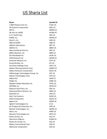
Minimum Air VelocityFinned Tubular ElementsMinimum Air VelocityOpen Coil Elements1300*APPUMPEA P400400300300200200EMPERATU RPERATUREE (H500———— ULIR TTE MTANLEMI600500100T AIR700MU600800A XIUMMINLEMIMTE900FM FAXLIRRE0 0 F81700INAETUAT*81 800RPE1000*82 19001100MINIMUM AIR VELOCITY (fpm)82 (H - 10EA 0 TP FUM INLP A ETPP AIL1000S ONLY)EURAT LY)RE ONMP STE NR ATIOIC11001200LICATI O N1200MINIMUM AIR VELOCITY (fpm)*1300———— UL100002468 10 12 14 16 18 20 22 24 26 28 302HEATER FACE AREA (KW/FT2)*Maximum allowed watt density: 28.9 KW/FT2)Face Area 68 10 12 14 16 18 20 22 24 26 28 30HEATER FACE AREA (KW/FT2)*Maximum allowed watt density: 17.0 KW/FT2)Example:(H-2 1/2") (W- 3/4")14425 KW UL Heater, Inlet 75 F12" H x 24" W, Open Coil ElementsFace Area KWFace AreaKW/Ft2 4(12-2 1/2") (24- 3/4") 1.53 Ft 214425 16.31.5316.3 KW/Ft 700 fpmKW/Ft2 2Pressure Drop Through Heater (inches water)*.35- 5COLUM NS.30TUBULAR.20EOPNCOIL"- 8DEPFCOILNNEDPRESSURE DROP (inches water).25OTHFI.15.10.0505001000VELOCITY (fpm)15002000*This is an estimate ony and will vary with the specific construction of each heater. Calculations for specific heaters can be run on a computer program but are still rough approximatoions. Actual pressure drops can only be found by performing pressure drop tests on the actual duct heater after manufacture.18BRASCH MANUFACTURING
How to Calculate Line CurrentsTo determine the line current use the following formulaeSingle Phase(IL) Line CurrentLINE CURRENT (IL) in amperes WATTAGEVOLTAGE1øVoltage{Three PhaseLINE CURRENT (IL) in amperes WATTAGEVOLTAGE X 1.73NOTE: This is the current which will flow in each of the three lines, regardless of whether the elements are wye or delta PPLY WIRE AND LINE TERMINALS SIZING—UL requires thatthe line terminals in duct heaters be sized to accept conductorswhich are rated to carry at least 125% of heater line current. Heatersare provided with properly sized terminals at no extra charge. Fieldsupply wires must be sized to carry at least 125% of heater line current except when the heater is for space heating, is over 50KW andnot more than 3 wires in the conduit—may be sized at 100% ofheater line current.Supply conductors must have insulation rated atleast 75 C (167 F).BULLETIN A102-119
Wiring Diagram Control System 1Single or multi-step heater with de-energizing magnetic contactors per step, fusing per NEC and 24 volt transformer. Can be controlled by a single/multiple stage room or duct thermostat, remote step controller and modulating room or duct thermostat or signal from various electronic building systemcontrols. Standard options available include disconnecting magnetic contactors, interlocking disconnect switch and remote control panel. For otheroptions, consult factory or the local Brasch representative.20BRASCH MANUFACTURING
Wiring Diagram Control System 2Multi-step heater with de-energizing magnetic contactors per step, built-in step controller, fusing per NEC and 120 bolt transformer with primary fusing. Canbe controlled by a modulating room or duct thermostat or signal from various electronic building system controls. Standard options available include disconnecting magnetic contactors, interlocking disconnect switch and remote control panel. For other options, consult factory or the local Brasch representative.BULLETIN A102-121
Wiring Diagram Control System 3Multi-step heater with SCR Vernier control. Step 1 is SCR and is equal to each step on the step controller. Controls include SCR's, step controller, deenergizing magnetic operating contactors per step and safety contactor, fuses per NEC, and 120 bolt transformer with primary fusing. Can be controlledby a modulating room or duct thermostat or signal from various electronic building system controls. Standard options available include disconnectingmagnetic contactors, interlocking disconnect switch and remote control panel. For other options, consult factory or the local Brasch representative22BRASCH MANUFACTURING
Wiring Diagram Control System 4Total SCR controlled heater with SCR's, de-energizing magnetic safety contactors per step and safety contactor, fuses per NEC, and 24 volt transformer.(Above approximately 100 amps total heater load, the economics of System 3 should be considered). Can be controlled by a modulating room or ductthermostat or signal from various electronic building system controls. Standard options available include disconnecting magnetic contactos, interlockingdisconnect switch and remote control panel. For other options, consult factory or the local Brasch representative.BUL LSECTHI NMAA1N0 U2 F- 1A C T U R I N G B U L L E T I NRA23
UL/NEC Requirements*REQUIREMENTDOUBLE SAFETY PROTECTIONUL 1996, Paragraph 23.3.1:"A duct heater shall be equipped with one or more automatically resetting temperaturelimiting controls, as determined by 23.3.3, that will disconnect the heating element or elements from the supply circuit to prevent temperatures from exceeding the limits specified.These temperature-limit
BRASCH MANUFACTURING General: Electric duct heaters and air handling coils shall be as manufactured by Brasch Manufacturing Company, Inc.Voltage, size, KW, steps and control voltage shall be as scheduled.Three phase heaters shall have balanced phases. 1. Heaters shall be UL Listed for zero clearance an shall meet all NEC require-ments. 2.