Transcription
Application TechniqueMETSO Neles ND9000 Valve Controller via HART to thePlantPAx Process Automation System
Important User InformationSolid-state equipment has operational characteristics differing from those ofelectromechanical equipment. Safety Guidelines for the Application, Installationand Maintenance of Solid State Controls (publication SGI-1.1 available fromyour local Rockwell Automation sales office or online at http://www.rockwellautomation.com/literature/) describes some important differencesbetween solid-state equipment and hard-wired electromechanical devices.Because of this difference, and also because of the wide variety of uses for solidstate equipment, all persons responsible for applying this equipment must satisfythemselves that each intended application of this equipment is acceptable.In no event will Rockwell Automation, Inc. be responsible or liable for indirect orconsequential damages resulting from the use or application of this equipment.The examples and diagrams in this manual are included solely for illustrativepurposes. Because of the many variables and requirements associated with anyparticular installation, Rockwell Automation, Inc. cannot assume responsibilityor liability for actual use based on the examples and diagrams.No patent liability is assumed by Rockwell Automation, Inc. with respect to useof information, circuits, equipment, or software described in this manual.Reproduction of the contents of this manual, in whole or in part, without writtenpermission of Rockwell Automation, Inc., is prohibited.Throughout this manual, when necessary, we use notes to make you aware ofsafety considerations.WARNING: Identifies information about practices or circumstances that can cause an explosion in a hazardous environment,which may lead to personal injury or death, property damage, or economic loss.ATTENTION: Identifies information about practices or circumstances that can lead to personal injury or death, propertydamage, or economic loss. Attentions help you identify a hazard, avoid a hazard, and recognize the consequence.SHOCK HAZARD: Labels may be on or inside the equipment, for example, a drive or motor, to alert people that dangerousvoltage may be present.BURN HAZARD: Labels may be on or inside the equipment, for example, a drive or motor, to alert people that surfaces mayreach dangerous temperatures.IMPORTANTIdentifies information that is critical for successful application and understanding of the product.Allen-Bradley, Rockwell Software, Rockwell Automation, and TechConnect are trademarks of Rockwell Automation, Inc.Trademarks not belonging to Rockwell Automation are property of their respective companies.8Rockwell Automation Publication PROCES-AT020A-EN-P - September 2013
IntroductionThe purpose of this document is to provide a simple proven step by step guide tointegrating and configuring the Metso Neles Valve controller into the RockwellAutomation PlantPAx process Automation System using the 3 process networks.These include HART, FOUNDATION Fieldbus and Profibus PA. Thisdocument is intended to provide a tested method to quickly connect to andcommunicate with the field device. I t is not meant to show all of the methodsnor is it intended to be a detailed document pertaining to all of the features,capabilities and application of the field devices.To supply robust system solutions, Rockwell Automation pre-tests many thirdparty manufactured HART, FOUNDATION Fieldbus, and PROFIBUS PAfield devices in the system test laboratory for compatibility with the RockwellAutomation PlantPAx process automation system. Each field device is connectedto the PlantPAx system and is subjected to interoperability testing proceduressimilar to operating procedures in your plant. The results of each field test arerecorded in a test report for integration planning purposes.For this field device, an additional step provides an “Integration Document” and“Interoperability Statement” for each tested instrument. The IntegrationDocument provides information on installation, configuration, startup, andoperation of the integrated system. The Interoperability Statement is assurancethat the field device meets PlantPAx system interoperability performancemeasures, as established by Rockwell Automation . Both the IntegrationDocument and Interoperability Statement help reduce risk with ease ofintegration.The overall purpose of this document is to provide you with proven solutionsthat combine field instrumentation with fieldbus networks, such as HART,FOUNDATION Fieldbus, and PROFIBUS PA networks, with assetmanagement capabilities and Rockwell Automation’s system capabilities toprovide a total engineered solution.Through pre-engineered integration in support of increasing requirements forplant-wide control, the document offers the following benefits: Reduced integration costs throughout engineering, commissioning, andstart-up Optimized plant availability and output Ensured product quality and consistency Optimized traceability to meet regulatory demands Predictive maintenance through intelligent instrumentsRockwell Automation Publication PROCES-AT020A-EN-P - September 20139
For new construction, process improvements at an existing plant, or operatingcost reductions, the benefits are: Reduces risk, reduces integration costs, and protects investment with preengineered interoperability. Both companies believe open systems andstandardized interfaces bring maximum benefits. Advanced diagnostics with plant-wide control provides better visibility ofplant health and easier access to instrument diagnostics, which ultimatelyleads to faster troubleshooting and improves decision-making. Collaborative lifecycle management leads to improvements in design,engineering, and startup and support of plants. This collaborationincreases productivity, manages information about instrumentation assets,optimizes plant assets, and results in a complete lifecycle managementsolution.Application OverviewThis document provides a step-by-step approach to integrating a Metso Nelesvalve controller using HART into the PlantPAx Automation System.SectionDescribesApplication overviewDetails about the field device and control systemExample systemSpecifications on the required hardware and software componentsInstallationHow to install and connect the field device, linking device and other componentsConfigurationHow to: Configure the HART I/O Configure the measurement instrumentVisualizationHow to implement and configure a graphical display of device informationThe ControlLogix platform provides a full range of input and output modules tospan a wide variety of applications. The ControlLogix architecture usesproducer/consumer technology, allowing input information and output status tobe shared by all ControlLogix controllers in the system.This integration document assumes you have a working knowledge ofControlLogix systems.10Rockwell Automation Publication PROCES-AT020A-EN-P - September 2013
The ControlLogix platform provides a robust EtherNet/IP backbone forcommunication to process fieldbus networks. The PlantPAx architecture usesproducer/consumer technology, allowing inpMut information and output statusto be shared by all ControlLogix controllers in the system. This integrationdocument assumes you have a working knowledge of ControlLogix systems. Formore details regarding the equipment and tasks described in this document seeadditional resources.The diagram above is an example of a PlantPAx system used for testing. It is basedon EtherNet/IP network backplane with I/O for HART and 1788-EN2PARand EN2FFR Linking devices for FF and Profibus PA. The PC contains thefollowing software packages for Programming, Configuring the system and fieldcomponents: RSLogix V20, RSLinks, RSfactory TalkView and Asset Center.Other tools are available from the device vendors such as Hand Heldprogrammers and Software packages.This integration document assumes you have a working knowledge ofControlLogix systems. For more details regarding the equipment and tasksdescribed in this document go to the Rockwell Automation Literature library atwww.rockwellautomation.com and www.rockwellautomation.com/knowledgebaseand to Metso’s website. Before starting, make sure to load the appropriateFirmware. AOP, GSD, DTM and DD files.Rockwell Automation Publication PROCES-AT020A-EN-P - September 201311
The AOP can be downloaded from Rockwell Hiprom at www.hiprom.com.Device files can be downloaded from www.metso.com/valves.Device InformationIntelligent Valve Controller, Series ND9000Neles ND9000 is a top class intelligent valve controller designed to operate onany valve and actuator type in all industry areas. With unique performancefeatures, it ensures maximum control accuracy in all operating conditions. Thediagnostic capabilities provide the user with valuable information as a basis forpredictive maintenance. For more details see ND9000 Installation, Maintenanceand operators Instructions (7ND9071en.pdf ) (www.metsoautomation.com/ND9000). Enclosure options– ND9100: Anodized aluminum alloy and polymer composite– ND9200: Anodized aluminum alloy and tempered glass– ND9300: Full 316 stainless steel– Communication options– ND9000H HART– ND9000F,– FOUNDATION Fieldbus H1– ND9000P Profibus PA Wide coverage of hazardous area approvals (Explosion/Flame proof,Intrinsically safe)– ATEX, IECEx, cCSAus, Inmetro, GOST R Single device for double and single-acting actuators, as well as linear androtary valves Simple and fast commissioning (only 4 parameters needed: signal, rotatingdirection, actuator type, fail safe action) 3 types of spool valves for different actuator sizes– Small actuators 1 dm3 2 mm spool valve 5 Nm3/h / 3 scfm– Medium actuators 1 dm3 - 3 dm3 3 mm spool valve 12 Nm3/h / 7scfm– Large actuators 3 dm3 6 mm spool valve 38 Nm3/h / 22 scfm The adaptive control algorithm together with the intelligent nozzle /flapper system ensures best control results even under changing processand environmental conditions.– Dead band 0.1% / hysteresis 0.5% (according to IEC61514measured with a diaphragm actuator at moderate constant-load inambient temperature). By continuous monitoring of the supply and actuator pressure– leaks in the control system can be identified and compensated– best control results will be achieved even with external instrumentationcomponents (volume booster)12Rockwell Automation Publication PROCES-AT020A-EN-P - September 2013
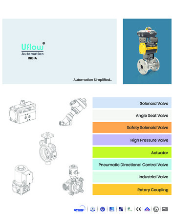
Valve specific functions (dead angle, cut-offs and valve characterization)integrated. Local user interface enables easy usage of the device– Parameterization and calibration– Measurements: input signal, valve position, temperature, supplypressure, actuator pressure difference– All warnings, alarm messages as clear text messages in English, German,French Extremely high vibration resistance Continuous self-monitoring, as well as online, counter and lifecyclediagnosis enables– rapid detection of faulty components– accurate assessment of the specific valve performance– statement about negative process and environmental influences– assessment of the performance of the superior controller All diagnostic data are stored in the device over the entire operating period(up to 25 years) The event log stores up to 8000 events (alerts, alarms, notes) Performance view Supports FDT/DTM technology Advanced Offline-Tests according IEC61514 / ISA 75.25-2000– Multipoint step response test– Hysteresis test– Valve analysis test– Dead band testThe Performance View of the Metso Valve Manager graphically displays indexesof the valve, actuator and positioner, as well as indexes of control performanceand the application environment. Report will show explanations of the status ofeach component and guidelines for recommended actions.Rockwell Automation Publication PROCES-AT020A-EN-P - September 201313
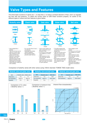
Figure 1 - Performance ViewFigure 2 - Example Diagnostics Trend14Rockwell Automation Publication PROCES-AT020A-EN-P - September 2013
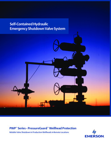
Figure 3 - Multipoint Step Response TestControl SystemThe control system includes these components:ComponentDescriptionControllerThe ControlLogix controller is a modular, high performance control that uses RSLogix 5000 programming software toconfigure, program, and monitor a system.HART interfaceThe PlantPAx system has a number of HART interface I/O options including the 1756- OF8H, Flex 1794, Compact, 1769 andpoint 1734 options. For this configuration the 1756-OF8H was used though any of the above HART options mentionedabove are feasible.Programming softwarePlantPAx is an easy object-oriented, explorer-based, drag-and-drop configuration that allows you to build complexprocess functions. Furthermore, the software allows you to mix and match IEC61131-3 compliant programminglanguages. All supported programming languages share the same development environment, tag database, and userinterface, resulting in reduced training and higher productivity.Visualization softwareFactoryTalk View Site Edition software is HMI software program for monitoring, controlling, and acquiring data frommanufacturing operations throughout an enterprise. A generic display provides a graphical representation via faceplatesof the field instrument.Hardware ComponentsComponentDescriptionMetso Neles valve controllersND9000H1756-OF8H I/O moduleHART output moduleAllen-Bradley EtherNet/IP Bridge1756-L75 ControlLogix controller with a 1756-EN2TmoduleFor further details, see the PlantPAx Process Automation System SelectionGuide, publication PROCES-SG001.Rockwell Automation Publication PROCES-AT020A-EN-P - September 201315
Software ComponentsComponentCatalog NumberRSLogix 5000 Enterprise Series programming software,Professional editionIncludes: RSLinx Classic software RSLinx Enterprise software9324-RLD700NXENEFactoryTalk View Site Edition (SE) software (optional)9701-VWSXXXXXENEFactoryTalk AssetCentre server9515-ASTSRVRENEFactoryTalk AssetCentre process device configuration9515-ASTPRDCFENEFieldCare Standard Asset Management software(optional)—For specifications of the engineering workstation (EWS) and operatorworkstation (OWS), see the Integrated Architecture for Process Control SystemRecommendations Reference Manual, publication PROCES-RM001.Installation and WiringThe following sections provide instructions on how to connect the HART(ND9000H) valve controller to a DCS system.Connect a ND9000H HART Valve ControllerThe ND9000H is powered by a standard 4–20 mA current loop that alsofunctions as a carrier to the HART communication.The input signal cable is led through a M20 x 1.5 cable gland, or 1/2 NPT cable glandConnect the conductors to the terminal strip as shown below. It is recommendedthat the earthing of the input cable shield be carried out from the DCS end only.The position transmitter is connected to 2-pole terminal PT as shown below.The position transmitter needs an external power supply.16Rockwell Automation Publication PROCES-AT020A-EN-P - September 2013
Figure 4 - ND9000H TerminalsConnect a ND9000F Foundation FIELDBUS and a ND9000P Profibus PAValve ControllersThe ND9000F is powered by FOUNDATION fieldbus (IEC 61158-2). TheND9000P is powered by Profibus PA (IEC 61158-2). The same bus cable is usedalso for the fieldbus communication. The bus cable is led through a M20 x 1.5 cable gland, or 1/2 NPT cable glandConnect the conductors to the terminal strip as shown in below.Rockwell Automation Publication PROCES-AT020A-EN-P - September 201317
Figure 5 - ND9000F and ND9000P TerminalsIf ND9000F is used without supply pressure to make FF function blocks tooperate normally shall simulation mode used or supply pressure diagnostics shallbe disabled.Assembly Related Parameter SettingsThe configuration parameters shall be defined based on valve assembly.Parameters can be set via device DTM or via LUI (local user interface). Fordetails see ND9000 Installation, Maintenance and operators Instructions(7ND9071en.pdf ) (www.metsoautomation.com/ND9000).Fieldbus ConnectorThe connection technology of FOUNDATION Fieldbus allows measuringdevices to be connected to the fieldbus via uniform mechanical connections, suchas T-boxes, distribution modules, etc. This connection technology, which usesprefabricated distribution modules and plug-in connectors, offers substantialadvantages over conventional wiring. Field devices can be removed, replaced or added at any time during normaloperation. Communication is not interrupted. Installation and maintenance are significantly easier. Existing cable infrastructures can be used and expanded instantly, e.g.when constructing new star distributors using 4-channel or 8-channeldistribution modules.18Rockwell Automation Publication PROCES-AT020A-EN-P - September 2013
Connect a 2-wire Field Instrument to the HART Input ModuleHART communication is active only with current inputs. Connect a 2-wire fieldinstrument to any channel of the 1756- output module in a 2-wire configurationfor current input. This figure shows a 2-wire field instrument connected tochannel 4. For the example we used channel 0.Figure 6 - 1756-OF8H Wiring DiagramVoltage outputs use the terminal block pins VOUT and RTN. Current outputsuse the terminal block pins IOUT and RTN.Rockwell Automation Publication PROCES-AT020A-EN-P - September 201319
Connect a HART Handheld Device (optional)Connect the Field Xpert device by one of these methods: Connection across load resistor. Connection across RN221N (Ex version).Turn power on to both the handheld device and the modem to establish theBluetooth connection.20Rockwell Automation Publication PROCES-AT020A-EN-P - September 2013
Configure the HART Modulevia RSLogix 5000 Software1. Use the RSWHO Active utility to verify the active devices as shown below.2. In RSLogix 5000 software, create a new project.3. In the I/O Configuration tree, right click, New Module.4. Select the controller and enter the configuration information.5. Click OK.Rockwell Automation Publication PROCES-AT020A-EN-P - September 201321
6. Right-click the controller backplane and choose New Module.7. Select the 1756-OF8H module.22Rockwell Automation Publication PROCES-AT020A-EN-P - September 2013
8. On the General tab, choose Analog and HART PV for the Data type.9. On the Configuration tab, enable HART for each channel connected to aHART device.Each channel must be enabled to pass HART data to the controller.10. Choose Pass through to Once per channel scan (the fastest and best forasset management software).11. Click Apply and then click OK.12. Display Controller Tags to verify that the tag database was created.Rockwell Automation Publication PROCES-AT020A-EN-P - September 201323
13. Go online with the ControlLogix controller and download the controllerproject.14. From the HART Device Info tab in the HART module properties, verifythat the instrument/device is connected.15. Display Controller Tags again to verify that the HART device isconnected.A connected instrument will display values in PV, SV, TV, and FV. This tagexample shows that the HART input module is in slot 6.Configure the HART Modulevia FactoryTalk AssetCenterSoftware24FactoryTalk AssetCenter is the Allen-Bradley’s FDT-based, plant assetmanagement software to configure intelligent field devices.Before beginning this process, make sure the DTMs have been dwnloaded fromthe vendor website, imported, and installed.Rockwell Automation Publication PROCES-AT020A-EN-P - September 2013
1. After installing the appropriate DTM files, start AssetCenter software andopen a new project.2. To update the DTM catalog, choose Tools DTM Catalog.3. To verify that the DTMs are installed, click Scan Now.4. Close the DTM catalog.Rockwell Automation Publication PROCES-AT020A-EN-P - September 201325
5. To configure the DTM network paths, choose Tasks DTM Networks.6. Select the name of the DTM network on the tree to the left and then clickAdd DTM.26Rockwell Automation Publication PROCES-AT020A-EN-P - September 2013
7. Select the chassis and click OK.The tree looks like this.8. Select the chassis and click Add DTM.Rockwell Automation Publication PROCES-AT020A-EN-P - September 201327
9. Select the module and click OK.The module should now be added to the tree.10. Select the module and click Add DTM.11. Enter the slot number and other configuration data.28Rockwell Automation Publication PROCES-AT020A-EN-P - September 2013
12. Press Enter to accept the data.Rockwell Automation Publication PROCES-AT020A-EN-P - September 201329
The tree should look like this.13. Select the module and click Add DTM.14. Choose the correct channel and click OK.30Rockwell Automation Publication PROCES-AT020A-EN-P - September 2013
15. Choose the appropriate device and revision and click OK.Use the native DTM even though the example shows the iDTM.The tree should look like this.Rockwell Automation Publication PROCES-AT020A-EN-P - September 201331
16. CLick DTM Information.17. Click Design.18. Choose Process Area New.32Rockwell Automation Publication PROCES-AT020A-EN-P - September 2013
19. Choose the instrument.20. Enter the name of the device.In this example, the name is Metso9000Hart 3.21. Click OK.Rockwell Automation Publication PROCES-AT020A-EN-P - September 201333
22. Right-click on the name of the device and choose Properties.23. Click DTM Addressing Info.24. Click the key on the right hand side of the screen.34Rockwell Automation Publication PROCES-AT020A-EN-P - September 2013
25. Select the device.26. Click OK27. Click OK.Rockwell Automation Publication PROCES-AT020A-EN-P - September 201335
28. Select the device and ch oose DTM View.36Rockwell Automation Publication PROCES-AT020A-EN-P - September 2013
29. Go online.30. Select any views desired and save the project.Configure the HART Modulevia CIP MessagesCIP message instructions let you access the following additional HARTinstrument parameters: Universal Command 3 Command 35 (PV range) Command 40 (simulate output current of primary PV) Command 44 (PV units) Command 48 diagnostic informationRockwell Automation Publication PROCES-AT020A-EN-P - September 201337
Diagnostic Messages:Command 48 provides information about an instrument when an instrument'stransmitter or sensor is not running properly. Command 48 produces a byte andbit based output that can be translated into specific error codes that can helpmaintenance personnel determine more specific details about abnormalconditions with HART instruments.Performance ConsiderationsKeep in mind these considerations when integrating HART instruments: The HART communication protocol has a relatively slow baud rate at1200/2400 bits per second. The 1756-IF8H HART module executes one HART command perinstrument at a time. Analog (4-20ma) data are delivered from all channelssimultaneously. The time of execution for Universal Command 3 is estimated from200 600 ms, but varies based on the complexity and response time of theinstrument. Upload and download time of instrument parameters to and fromFieldCare software can take several minutes depending on the instrument.38Rockwell Automation Publication PROCES-AT020A-EN-P - September 2013
Notes:Rockwell Automation Publication PROCES-AT020A-EN-P - September 201339
Rockwell Automation SupportRockwell Automation provides technical information on the Web to assist you in using its products.At http://www.rockwellautomation.com/support, you can find technical manuals, technical and application notes, samplecode and links to software service packs, and a MySupport feature that you can customize to make the best use of thesetools. You can also visit our Knowledgebase at http://www.rockwellautomation.com/knowledgebase for FAQs, technicalinformation, support chat and forums, software updates, and to sign up for product notification updates.For an additional level of technical phone support for installation, configuration, and troubleshooting, we offerTechConnectSM support programs. For more information, contact your local distributor or Rockwell Automationrepresentative, or visit ation AssistanceIf you experience a problem within the first 24 hours of installation, review the information that is contained in thismanual. You can contact Customer Support for initial help in getting your product up and running.United States or Canada1.440.646.3434Outside United States or CanadaUse the Worldwide Locator at on/support/overview.page, or contact your localRockwell Automation representative.New Product Satisfaction ReturnRockwell Automation tests all of its products to help ensure that they are fully operational when shipped from themanufacturing facility. However, if your product is not functioning and needs to be returned, follow these procedures.United StatesContact your distributor. You must provide a Customer Support case number (call the phone number above to obtain one) to yourdistributor to complete the return process.Outside United StatesPlease contact your local Rockwell Automation representative for the return procedure.Documentation FeedbackYour comments will help us serve your documentation needs better. If you have any suggestions on how to improve thisdocument, complete this form, publication RA-DU002, available at well Otomasyon Ticaret A.Ş., Kar Plaza İş Merkezi E Blok Kat:6 34752 İçerenköy, İstanbul, Tel: 90 (216) 5698400Publication PROCES-AT020A-EN-P - September 2013Copyright 2013 Rockwell Automation, Inc. All rights reserved. Printed in the U.S.A.
Rockwell Automation Publication PR OCES-AT020A-EN-P - September 2013 11 The ControlLogix platform provides a robust EtherNet/IP backbone for communication to process fieldbus networks. The PlantPAx architecture uses producer/consumer technology, allowing inpMut information and output status to be shared by all ControlLogix controllers in the .