Transcription
Proceedings of the IASS Annual Symposium 2020/21 andthe 7th International Conference on Spatial StructuresInspiring the Next Generation23 – 27 August 2021, Guilford, UKS.A. Behnejad, G.A.R. Parke and O.A. Samavati (eds.)Web-based, Interactive Platform for Polyhedral graphic StaticsHua CHAI ,a , Masoud AKBARZADEHa,b ,aPolyhedral Structures Laboratory, School of Design, University of Pennsylvania, Philadelphia, USAb GeneralRobotic, Automation, Sensing and Perception (GRASP) Lab, School of Engineering and AppliedScience, University of Pennsylvania, PA, 19146, USAAbstractThis paper introduces a web-based, interactive educational platform for the methods of 3D/polyhedralgraphic statics (PGS). The research includes developing libraries using JavaScript, Three.js, and WebGLto facilitate the construction of the reciprocal diagrams based on procedural and algebraic methods independent from any other software. The framework’s mathematical and computational algorithms allow theconstruction of global equilibrium for the systems, the changes in the magnitude of the internal forces bya simultaneous change in both form and force diagrams. It also visualizes the reciprocal and topologicalrelationship between the elements of the diagrams. This instant open-source application and the visualization interface provide a more operative platform for students, educators, practitioners, and designersin an interactive environment. It not only allows them to understand the topological relationship betweenthe diagrams but also provides a platform to explore and manipulate spatial structural forms and theirequilibrium for design purposes. Users can explore and design innovative, funicular spatial structures bychanging the boundary conditions and constraints through real-time manipulating both force distributionand geometric properties of the form. This online educational platform broadens the accessibility of themethod without the need for an intermediate software and platform. Multiple examples will contributeto the education of geometric methods of static equilibrium in three dimensions.Keywords: 3D graphic statics, form finding, web-based software, interactive structural design, Three.js1. IntroductionRecently, geometry-based structural design methods, known as Graphic Statics, have been extended to3D dimensions based on polygonal reciprocal diagrams and polyhedral reciprocal diagrams. The latteris based on a historical proposal by Rankine and Maxwell in Philosophical magazine, and is called3D/polyhedral graphic statics and will be the subject of this research [1, 2, 3, 4, 5, 6, 7, 8, 9, 10, 11].In polyhedral graphic statics, the equilibrium of the forces in a single node is represented by a closedpolyhedron or a polyhedral cell with planar faces. Each face of the force polyhedron is perpendicular toan edge in the form diagram, and the magnitude of the force in the corresponding edge is equal to thearea of the face in the force polyhedron. The sum of all area-weighted normals of the cell must equalzero that can be proven using the divergence theorem [12, 13, 7]. In some cases, a cell can have complexfaces (self-intersecting), which have multiple enclosed regions. The direction and the magnitude of theforce corresponding to a complex face can be determined by summing the area-weighted normals of allof the enclosed regions. As a result, the direction of the internal force in the members of the structuremight flip based on the direction of the face of a single force cell.1
Proceedings of the IASS Annual Symposium 2020/21 and the 7th International Conference on Spatial StructuresInspiring the Next Generation1.1. A valuable teaching toolThe geometric relationships between the form and force diagrams in an interactive environment helpstudents intuitively understand the internal force flow in structural systems and funicular forms. Thisproperty has been very well demonstrated using the methods of 2D graphic statics [14, 15]. For instance, a designer can change the magnitude of the applied forces by geometrically adjusting the forcediagram and observe the resulting change in the form of the structure and its internal forces. This geometric relationship can teach students what parameters control their design and how they can deliberatelymodify/optimize them to achieve specific design criteria.1.2. Accessibility of the methodsLearning the methods of polyhedral graphic statics might be challenging to begin with because of thefollowing reasons. First, it requires a necessary preparation to understand the reciprocal relationshipbetween the polyhedral cells and the geometry of the funicular forms. Secondly, all the existing implementation of polyhedral graphic statics heavily rely on modeling software such as Rhino and its relatedplugins such as PolyFrame [16] and 3D Graphic Statics [17] or another computational framework (e.g.,COMPAS [18]). Thus, it needs certain 3D modeling or programming skills which make it quite inaccessible for all users. Like many other new concepts and methodologies, practicing procedural methods andreviewing a series of examples can overcome this obstacle. However, the environment should be easilyaccessible.1.3. Web-based, interactive implementationsThe web-based environment is the most user-friendly platform that can be manipulated easily acrossdifferent knowledge backgrounds. Web technologies have been leveraged extensively to facilitate interoperability in software solutions and application programming interfaces (APIs). The WebGL [19], asone of the libraries in JavaScript [20], has advanced rendering and interaction capabilities, access geometric information over the network, and integrates the flexible data input mode. The innovations inWebGL and JavaScript allow the integration of advanced 3D graphic directly into web pages without additional plug-ins. Users can run three-dimensional scenes smoothly on the browser and support multipleplatforms. Although advanced 3D visualization is being used broadly for web applications in variousfields and modern graphic hardware is becoming increasingly available, most of the three-dimensionaldisplay scenes are based on fixed models, which cannot be simulated and displayed based on interactingselected parameters.1.4. Related worksOne of the most successful implementations of the methods of graphic statics is the eQUILIBIRUM 2.0[21] developed by Block Research Group (BRG) at ETH Zürich. This web-based platform provides adynamic learning and teaching environment for structural design and geometric equilibrium of forces.The implementation mainly focuses on 2D graphic statics and uses GeoGebra [22] - a suite of dynamicmathematical software that handles geometry, algebra, calculus, probability statistics, data tables, graphs,calculations. GeoGebra is the core computing program that serves as the fundamental drawing tool togenerate the line intersections and line segments to represent the relationship between force and form.This platform uses interactive 2D drawings to help designers and engineers with all skill levels to interact,understand, and utilize the methods in 2d. There is currently no educational platform for students to learnthe principles of polyhedral graphic statics. Students and researchers will significantly benefit from aninteractive platform with multiple examples elucidating the method and underlying relationship betweenthe elements of the form and force diagrams.2
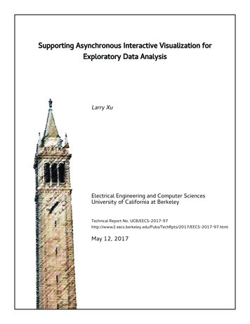
Proceedings of the IASS Annual Symposium 2020/21 and the 7th International Conference on Spatial StructuresInspiring the Next GenerationFigure 1: Three.js building architecture and interactive geometric data in both scenes1.5. Paper contributionThis research develops an educational web-based platform for the methods of polyhedral graphic statics. This implementation utilizes JavaScript and Three.js [23] libraries to take advantage of the dynamic transformations between the form and force diagrams for educational purposes. Its immediate accessibility through the web enables users to visualize and create various structural systems withcompression/tension-only and compression and tension combined elements. The possiblity to displaychanges in a real-time manner allows users to visualize how various parameters have changed the properties of the structural design and the equilibrium of forces.2. MethodologyThis section will introduce the principles of building a web-based platform based on Three.js, the algorithm generating geometric spatial forms, and the mechanisms by which users can interact with thegenerated structures. The method of interaction is through different UI combinations to change the datatype of the form and force diagrams and the displacement of the vertices manipulated by the mouse clickor dragging the vertex.2.1. Overall structureFigure 1 describes the 3D graphic statics scenes setup created by Three.js, including the structural components displayed in form diagram and polyhedron constructed in force diagram. Three.js as the primaryprogramming tool builds the fundamental framework of the platform to host the geometric objects usingthe following steps: (1) input Three.js and related libraries packages to define the algorithms to enhanceuser interaction; (2) set the canvas tag in the HTML page to draw responsive scenes, and divide the current window into two parts intended for the form and force diagrams; this feature will also adapt to the3
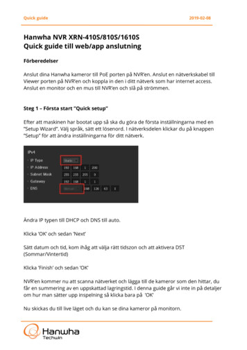
Proceedings of the IASS Annual Symposium 2020/21 and the 7th International Conference on Spatial StructuresInspiring the Next GenerationFigure 2: edges in form diagram corresponding to faces in force polyhedron.window size across various devices; (3) initialize and load the environment factors inside the scene suchas: (a) type, color, and intensity of lighting; (b) the closest and farthest viewing range of the camera,the camera tilt angle, aspect ratio, etc.; (c) generate rendering mode, set environment color and visibilityof shadow features; (d) setting up relevant auxiliary user interaction functions, such as rotation, translation, scaling, sectioning, and event settings for geometries through mouse clicking event and panel slidermanipulation. We will introduce it in the interaction section.According to Rankine’s principle of equilibrium [24] a closed force polyhedron represents the equilibrium of a spatial node of a structure [13]. This reciprocal relationship is at the crux of the methodsof polyhedral graphic statics, and it is salient to visualize both form and force diagrams separately andsimultaneously.The surface area in the force diagram corresponds to the thickness of the edges in the form diagram. Visualizing this relationship as the force magnitude in the member of the designed structure can intuitivelyeducate the relationship between the form and the force diagrams. In some examples a user can onlymove the support locations while in some others there is a control over the location of the applied load aswell as the magnitude of the force in the force diagram. Any manipulation by the user results in a changein the force magnitude in the members of the funicular form which will be visualized in the interactiveenvironment. This feature is designed to give an intuitive feedback to designers and structural engineersto realize the force flow in various configurations and have various design options without sophisticatedcalculations which may save time and effort in very early stages of the design (Figure 2).4
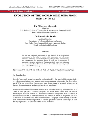
Proceedings of the IASS Annual Symposium 2020/21 and the 7th International Conference on Spatial StructuresInspiring the Next GenerationFigure 3: (a) Form diagram showing faces and cells; (b) divide space to A,B,C, and in force diagram draw linefrom point A to point B perpendicular to the normal of triangle; (c) calculate the intersection point C; (d) draw therest edges and define the force direction; (e) repeat the previous steps to finish the corresponding triangle and f)define the compression force as f3 .2.2. Construction processWe will introduce how to build a 3D interactive platform in a web environment, the immediate environment setup with a user-operable visual interface as a container to integrate the content to carry allthe back-end data and front-end objects. Algorithms are utilized to calculate spatial geometric linearintersections to generate basic triangles to form the final force polyhedron.2.2.1. Three-dimensional environment setupsThe scene corresponds to the real-world spatial environment and plays the role of a container; all objects,cameras, light sources need to be placed inside the window frame, which is the view-port of the scene.The next step is setting up the cameras. Three.js framework typically defines two main types of cameras- orthogonal and perspective cameras. The purpose is to map the model in three-dimensional space tothe two-dimensional plane. The size of the geometry in the orthographic projection remains the same,and in perspective, the projection will appear large near and small far. Each scene has an independentcamera, but the viewing angle is controlled simultaneously using the mouse left-click event. For properlypresenting the models, the lighting is created to enhance the visual contact with all the relevant interactions. The light source corresponds to all kinds of light in the real world, such as ambient light, parallellight, point light, and hemispheric light. In order to make objects appear more realistic in the scene,it is necessary to simulate the effect of displaying objects in different environments. Lastly, render the5
Proceedings of the IASS Annual Symposium 2020/21 and the 7th International Conference on Spatial StructuresInspiring the Next GenerationFigure 4: Gumball selection at vertices of form diagram (left) and corresponding force polyhedron showingarea-weighted normals (right).geometric model and material into accurate content by calling the rendering function to render all theelements and visually present them in a window frame.2.2.2. Generate geometric modelAll the examples are calculated on the geometric vector. It plays a significant role in Three.js programming because the display screen is a coordinate system, and the user’s interaction with the geometry ofthe form and force is the result of the object’s curvilinear motion in this coordinate system, and whatdescribes these curvilinear motions are vectors. The use of vectors is a proper way to simulate the correspondence transform by data manipulation. The final force polyhedron can be obtained from the trialfunicular [2]. The final form diagram can be drawn by spatial vector calculation in a given support locations. Figure 3 shows the steps starting from the apply load, followed by the right-hand rule to generatethe corresponding vectors that construct force faces. The direction of the vector is equal to the normalvector of faces in the form diagram and intersects the line where the two vectors meet to create triangleABC. The algorithm 1 is generated to construct force polyhedron geometry.Since the length of the vector can be chosen to any value, the distance variation is the size of the forcediagram. We will describe this in the next section on interacting with the existing model to obtaindifferent designs.6
Proceedings of the IASS Annual Symposium 2020/21 and the 7th International Conference on Spatial StructuresInspiring the Next GenerationAlgorithm 1: Computing the intersecting P3Input: Line1dir , Point 1 , Line2dir , Point 2 , start point and end point with vector directionsOutput: Psect the intersection of two lines.Function LinessectPt (L1dir , Point 1 ,L2dir , Point 2 ,):L1dir : [newT HREE.Vector3()] # generate vector directions L1L2dir : [newT HREE.Vector3()] # generate vector directions L2for x, y, z L1dir doL1dir : normalize # get norm vectorfor x, y, z L2dir doL2dir : normalize # get norm vectorP1 P2vec : [newT HREE.Vector3()] # generate vector P1 to P2for x, y, z P1 P2vec doP1 P2vec : Point 2 Point 1 # vector directionP2 P3 norm norm(cross(P1 P2vec , L1dir )) # distance from P2 to L1Point 3 [newT HREE.Vector3()]for x, y, z Point 3 doPoint 3 Point 1 (P1 P2vec L1dir ) L1dir # projection of Point3cosθ Math.abs(L1dir L2dir )k pt [newT HREE.Vector3()]if cosθ 0 # the angle between L1dir L2dir thenk pt Point 3if cosθ 0 # the angle between L1dir L2dir thentanθ Math.sqrt((1 Math.pow(cosθ , 2)))/cosθk pt3 P2 P3 norm /tanθk1 pt newT HREE.Vector3((Point 3 k pt3 norm L1dir ))k2 pt newT HREE.Vector3((Point 3 k pt3 norm L1dir ))P2 K1vec newT HREE.Vector3((k1 pt Point 2 ))P2 K2vec newT HREE.Vector3((k2 pt Point 2 ))D1 norm(cross(P2 K1vec , L2dir ))D2 norm(cross(P2 K2vec , L2dir ))if D1 D2 # the y coordinate of n f thenk pt k1 ptelsek pt k2 ptreturn PsectbeginL1 # vector of p1L2 # vector of p2P2 P3 norm P1 P2vec L1dir # the cross product of the first two edgesPsect K pt # projection at one of the edge7
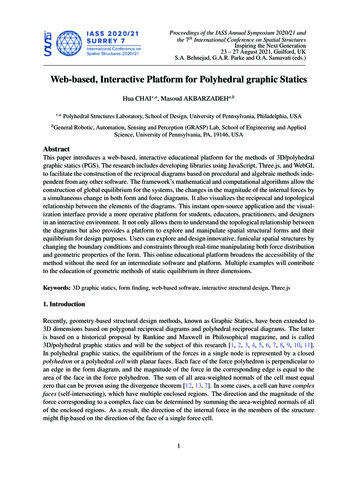
Proceedings of the IASS Annual Symposium 2020/21 and the 7th International Conference on Spatial StructuresInspiring the Next GenerationFigure 5: (a) Compression-only and tension/compression combined design from same force diagram; (b) datamanipulation in force diagram resulting more flattened bridge.2.3. User InteractionCompared to most web-based 3d platforms that can only visualize objects from various camera perspectives, no other properties can be changed. In this research, we not only provide fundamental operationssuch as visual rotation and scaling, but most importantly, add user manipulation and interactivity, with aback-end algorithm that instantly displays the new structure obtained with each changed parameter.2.3.1. Interpreted gumball functionThe most common interaction on the browser is to detect whether a physical graphic is located belowthe mouse pointer by clicking on a 3D object—for example, the object picking operation. The selectedobject changes its color, visibility, other properties, and the object’s animation is activated. The processof selecting is precisely the opposite of the process of drawing a physical graphic. Since the mouse clickcorresponds to the browser’s screen coordinates (X, Y) and the Three.js canvas is a 3D scene, the 2Dcoordinates of the screen click need to be converted to Three.js 3D coordinates (X’, Y’) to determine themodel of the clicked object. The method of coordinate pickup involves complex matrix operations, andthe Three.js library provides the THREE. Raycaster object for mouse pickup, which is a traditional objectspace-oriented select method. The constructor is used as the new Raycaster (origin, direction, near, far):(1) the origin is the starting vector of the Raycast, which is the camera’s location; (2) direction is thevector of the light projection (normalized). Utilizing the Raycaster function to determine the intersectiondetection of the models. The array is sorted by distance, and the closest to the viewpoint is the first oneto be selected.Figure 4 shows the mouse clicking event at the vertices of the form diagram. By selecting a movablepoint, the edges will move their position. Force direction will change accordingly and the force diagram8
Proceedings of the IASS Annual Symposium 2020/21 and the 7th International Conference on Spatial StructuresInspiring the Next Generationwill show different colors to indicate tension moment (color in red) at f3 . Related mouse event interactionalgorithm 2 is showing here:Algorithm 2: Creating mouse click eventInput: ctrl pts , selectob jname # define interactive verticesOutput: tr f mctrl # adding gumball to selected objectFunction onMouseDown(event):rayCaster.setFromCamera(mouse, camera)varintersects rayCaster.intersectOb jects(Ctrl pts )# option to add more objs as group dataif event.button 2 # detach gumball thentr f mctrl .detach()if event.button 0&&intersects[0] # add gumball thenselectOb j intersects[0].ob ject # save current select objconsole.log(”selectob j.name ” intersects[0].ob ject.name.charAt(2))lastPosition selectOb j.position # save current select obj positiontr f mctrl .attach(selectOb j)return tr f mctrl2.3.2. Panel controllerNowadays, the front-end technologies for web development are usually implemented in JavaScript andCSS. Jquery [25] refers to the integration of these programming packages in the formation of a development framework. It can be leveraged for web front-end development in designing web pages, respondingto user behavior, and using the framework to more easily implement features such as web animationsand user interactions. One of the essential features to improve user experience is applying Jquery toachieve asynchronous calls. After the user submits a request to the site without waiting for the serverto return a response, they can continue to operate the web page or continue to make requests. Then atthe appropriate moment, user will get the returned results. With this technique, it is possible to respondrequests without loading the whole contents.In the existing examples, control panels are provided below the form and force diagrams. The displacement of the force diagram at a fixed point position is integrated with the changeable parameters, andthe slider and click-box UI are associated with the back-end data. For manipulating the values on theslider, the corresponding geometry of the form or force will change accordingly. In the bridge exampleshown in Figure 5, by adjusting the horizontal distance of the support point, the structural members ofthe bridge will switch from compression only to a combination of tension and compression in real-time.Additionally, the curvature of the bridge will also change, with the vertex position farther from the applied load face by adjusting the position of the force polyhedron fixed point, and the bridge tends to bemore flattened. If the slider is moved in the other direction, it will produce an arch bridge with significantcurvature. The operation described above is an intuitive reflection of how the design can be selected andoptimized by controlling the geometry position.3. Conclusion and future workThis paper explained how to build a web-based 3D interactive platform for polyhedral graphic statics(Figure 6). The mathematical algorithm of spatial geometry is used to demonstrate the reciprocal principle of 3d graphic statics. Users can change the corresponding data to get different structural designsthrough various interactive methods with interpreted UI designs. Furthermore, this intuitive presentation9
Proceedings of the IASS Annual Symposium 2020/21 and the 7th International Conference on Spatial StructuresInspiring the Next GenerationFigure 6: Live mode of the interactive Polyhedral Graphic Statics platform.provides an accessible, convenient and faster response environment. In the next step, we will providemore possibilities for enhancing the online structural design. It is also essential to improve other platform features to demonstrate its educational nature for users better. For example, adding introductiontexts to explain the details - when the user moves the mouse to the geometry, a prompt 2D layer willappear, illustrating more detailed content with highlighted colors. Eventually, the design can be exporteddirectly to other formats and save the geometries.4. AcknowledgmentThis research was funded by National Science Foundation CAREER Award ( NSF CAREER-1944691CMMI).10
Proceedings of the IASS Annual Symposium 2020/21 and the 7th International Conference on Spatial StructuresInspiring the Next GenerationReferences[1] M. Rankine, “Principle of the equilibrium of polyhedral frames,” Philosophical Magazine, vol. 27,no. 180, p. 92, 1864.[2] M. Akbarzadeh, 3D graphic statics using reciprocal polyhedral diagrams. PhD thesis, ETH Zurich,Zurich, Switzerland, 2016.[3] A. Beghini, L. L. Beghini, J. A. Schultz, J. Carrion, and W. F. Baker, “Rankine’s theorem for thedesign of cable structures,” Structural and Multidisciplinary Optimization, 2013.[4] J. Maxwell, “On reciprocal figures and diagrams of forces,” Philosophical Magazine Series 4,vol. 27, no. 182, pp. 250–261, 1864.[5] J. Lee, Computational design framework for 3D Graphic Statics. PhD thesis, ETH Zurich, Department of Architecture, Zurich, 2018.[6] J. Lee, T. Van Mele, and P. Block, “Disjointed force polyhedra,” Computer-Aided Design, vol. 99,pp. 11–28, 2018.[7] A. McRobie, W. Baker, T. Mitchell, and M. Konstantatou, “Mechanisms and states of self-stress ofplanar trusses using graphic statics, part ii: Applications and extensions,” International Journal ofSpace Structures, vol. 31, no. 2-4, pp. 102–111, 2016.[8] A. McRobie, “The geometry of structural equilibrium,” Royal Society open science, vol. 4, no. 3,p. 160759, 2017.[9] A. McRobie, M. Konstantatou, G. Athanasopoulos, and L. Hannigan, “Graphic kinematics, visualvirtual work and elastographics,” Royal Society open science, vol. 4, no. 5, p. 170202, 2017.[10] M. Konstantatou, P. D’Acunto, and A. McRobie, “Polarities in structural analysis and design: ndimensional graphic statics and structural transformations,” International Journal of Solids andStructures, vol. 152, pp. 272–293, 2018.[11] M. Konstantatou, Geometry-based structural analysis and design via discrete stress functions. PhDthesis, University of Cambridge, 2020.[12] G. G. Stokes, Mathematical and physical papers. Cambridge: Cambridge University Press, 1905.[13] M. Akbarzadeh, T. Van Mele, and P. Block, “3D Graphic Statics: Geometric Construction ofGlobal Equilibrium,” in Proceedings of the International Association for Shell and Spatial Structures (IASS) Symposium, 2015.[14] R. Gerhardt, K.-E. Kurrer, and G. Pichler, “The methods of graphical statics and their relation tothe structural form,” in Proceedings of the First International Congress on Construction History,Madrid, pp. 997–1006, 2003.[15] T. Van Mele, L. Lachauer, M. Rippmann, and P. Block, “Geometry-based understanding of structures,” Journal of the international association for shell and spatial structures, vol. 53, no. 4,pp. 285–295, 2012.[16] A. Nejur and M. Akbarzadeh, “Polyframe, efficient computation for 3d graphic statics,” ComputerAided Design, vol. 134, p. 103003, 2021.11
Proceedings of the IASS Annual Symposium 2020/21 and the 7th International Conference on Spatial StructuresInspiring the Next Generation[17] O. Graovac, “3d graphic statics.” 2019.[18] T. Van Mele, T. Méndez Echenagucia, and M. Rippmann, “Compas: A framework for computational research in architecture and structures.,” 2017. https://compas.dev/.[19] M. Foundation, “Webgl - programming language,” 2011. https://www.khronos.org/webgl/.[20] B. Eich, “Javascript - programming language,” 1995.en-US/docs/Web/JavaScript/Language Resources.https://developer.mozilla.org/[21] T. Van Mele and P. Block, “equilibrium - an interactive learning platform for structural design.”https://block.arch.ethz.ch/eq.[22] M. Hohenwarter, “Geogbra - open source software,” 2002. https://www.geogebra.org/about.[23] R. Cabello, “Three.js - open source software,” 2010. https://threejs.org/.[24] W. Rankine, “Principle of the Equilibrium of Polyhedral Frames,” Philosophical Magazine Series4, vol. 27, no. 180, p. 92, 1864.[25] J. Resig, B. Aaron, and J. Zaefferer, “Jquery - javascript library,” 2006. https://jquery.com/.12
Keywords: 3D graphic statics, form finding, web-based software, interactive structural design, Three.js 1.Introduction Recently, geometry-based structural design methods, known as Graphic Statics, have been extended to 3D dimensions based on polygonal reciprocal diagrams and polyhedral reciprocal diagrams. The latter