Transcription
CRASH SAFETY OF HYBRID- AND BATTERY ELECTRIC VEHICLESRainer JustenProf. Dr. Rodolfo SchöneburgDaimler AG,Mercedes Car GroupGermanyPaper No 11-0096ABSTRACTBesides the suitability for daily use, sufficientcruising range, rapid battery charging times and anarea-wide service infrastructure, the crash safetyperformance will also play a key role for theconsumer’ s acceptance of electric vehicles. Inparticular, the electric energy storages and highvoltage systems are very challenging to the crashsafety performance.Already in the Mercedes-Benz S 400 HYBRID in2009, worldwide the first series-production vehiclewith a Lithium-Ion battery, a seven-stage safetyconcept has been implemented. It has an extremelyhigh performance in terms of functional andoperational safety during normal driving and anoutstanding crash performance in any real worldaccidents. Similarly, an intrinsically safe packagingconcept has been implemented in all other MercedesBenz Hybrid- and Battery Electric Vehicles, such asthe ML 450 HYBRID, the A-Class E-Cell, the BClass F-Cell, and the Smart Electric Drive. All safetyrelevant components of the high-voltage system havebeen integrated and protected in a safe manner. Thisis particularly true for the high voltage battery. TheHV-system has been isolated and protected againstany contacts, and it will be shut-off in any accident.In the future Mercedes-Benz hybrid- and electricvehicles, this safety concept will be enhancedconsistently, by utilizing the Mercedes-Benz safetyphilosophy of “Real Life Safety”. Its key elementsare:- A foolproof strategy to cut-off the high voltage inaccidents will prevent any electric shocks.- A concept of protection zones defines the accidentproof placement of all the safety relevant highvoltage components along with the highest possiblestructural safety.- Mechanical requirements for HV-componentsensure the electric insulation and shock-proofprotection.- An integrated safety concept shall prevent anycritical damages to the high voltage battery in case ofhigh crash loadings.This paper illustrates Daimler’s concept for crashsafety of hybrid- and electric vehicles.INTRODUCTIONDriven by severe fuel economy and CO2 emissionregulations, the automobile industry experiences afundamental change. Undoubtedly, hybrid andbattery electric vehicles will play a major role in thefuture individual traffic, with the focus on thesuitability for daily use, sufficient cruising range, andenergy charging time, at reasonable cost. The key toachieve these goals will be the energy storagetechnology, with Lithium-ion batteries as a futurebase. Since these new high voltage systems involvesome major challenges with regard to functionalsafety and operating safety, foolproofness and crashsafety, an equally important criterion for theacceptance of alternatively driven vehicles by thegeneral public will be the same high safety standardsas established for conventional vehicles.Justen 1
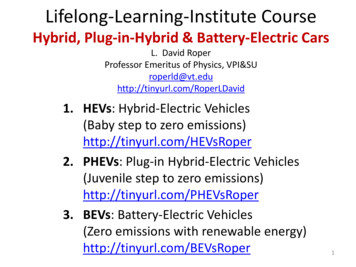
Some basic requirements to the integrity of the highvoltage system, such as the protection against electricshocks and the avoidance of fire or explosion ofenergy storages after a crash have already beenaddressed in the existing and currently discussedsafety standards for alternative vehicles with highvoltage systems (i.e. FMVSS 305, ECE R94/95,GB/T 18384, Attachment 111). This has been thebase for the development of the Mercedes-Benz S400 HYBRID, which has been launched in 2009 asthe world wide first series vehicle with a Lithium-ionbattery. As a result, the following seven-stage safetyconcept has been implemented:- An intelligent integration concept for the highvoltage battery to prevent critical damages even ifdirectly impacted during a crash.- The implementing of high requirements to themechanical stability of all high voltage components,combined with an ultimate shock-proof protection bycut-off and discharge during any accidents.- The consistent protection of other road users(compatibility) along with an enhancedimplementation of the new driver assistance andcrash avoidance systems.1. Color-code and contact protection for all highvoltage wiring with amply insulation and specialplugs,2. High-strength steel housing for the lithium-ionbattery located well protected in the extremely stiffzone before the fire wall,3. The battery cells are bedded in a shock absorbinggel, with a separate cooling circuit and a blow-offvent with burst disk,Figure 1. Mercedes-Benz hybrid and electricvehicles.4. Multiple safety interlock to automatically separatebattery terminals,5. Continuous short circuit and malfunctionmonitoring,6. Active discharging of the high voltage system inthe event of faults or fire,7. Pyrotechnical tripping of the voltage system in theevent of an accident.Based on the Mercedes-Benz “Real World Safety”philosophy, this concept will be enhancedconsistently in the future Mercedes-Benz hybrid andbattery electric vehicles. The key goals will be:- A high structural safety, based on protection zonesfor all high voltage components, surrounded bydeformation zones to manage the crash energy andspecifically programmed to the vehicle concept,while implementing intelligent light weight design.Figure 1 shows an overview of the actual MercedesBenz alternative propulsion vehicles. The tractionbattery of the A-class E-CELL and the Smart ElectricDrive is integrated on the floor of the passenger cell.In the F-CELL B-class, the hydrogen tank and thefuel cell stack are located on the floor, while thesmall HV-battery is well protected on the vehicle’srear axle. While the mild hybrid battery of the S 400HYBRID is located behind the right wheel arch, thefull hybrid battery of the ML 450 HYBRID is placedon the rear axle. All these integration conceptsimplement the highest possible crash protection in allaccident types.HIGH VOLTAGE CUTT-OFF IN THE EVENTOF AN ACCIDENTThe power train of both hybrid and electric vehiclesutilizes high voltages up to several hundreds of volts,for which severe safety regulations have beenJusten 2
legislated appropriately. Voltages above 30 V a.c.and 60 V d.c. respectively are in class B voltage,which requires already enhanced protection againstelectric shock. Nevertheless, the high voltage will becut-off from the battery and discharged in Mercedesvehicles in any serious accidents, in order to reliablyavoid any risks of electrical shocks even at very highvehicle damages [1]. By opening the batterycontactors, the high voltage must be reduced below60 V d.c. and 30 V a.c. accordingly in less than 5seconds. High voltage sub-systems with extremelyhigh energies in the link will be discharged activelyby a short circuit. Generally, this HV-deactivation islinked to the crash detection sensors for frontal /lateral / rear crash and rollover, and the subsequentactivation of the restraint system. Two differentswitch-off strategies have been implemented (Figure2):CRASH PROTECTION ZONES FOR HVCOMPONENTSExtremely important for the safety performance ofbattery electric and hybrid vehicles in any real worldaccidents is the well protected placement of all safetyrelevant components. This is particularly true for thehigh voltage battery which must not be damagedeven in very severe accidents resulting in any crucialcell damages or a loss of protection against contact.In order to define the protection zones for the bestpossible integration of energy storages, a specificstudy was conducted [2] by analyzing the damages ofapprox. 9000 vehicles involved in severe real worldaccidents, using the German In-Depth AccidentStudy (GIDAS) data base [3]. For each vehicle, thedeformations in the lower vehicle (floor) level wereplotted in a standardized 2-D grid. By consolidatingthe resulting deformation matrix with the accidentfrequency and severity, the probability of thedeformation of each vehicle cell in any crash type canbe evaluated accordingly. Figure 3 compares theresulting deformation matrix of a station wagon withthe vehicle intrusions in the standard crash tests.Figure 2. High-voltage cut-off in a crash.1. In minor severe accidents, i.e. frontal collisionswith activation of the seat belt pretensioners or the 1ststage of airbags, the high-voltage system will be shutdown reversibly. After the self diagnosis has notdetected any insulation faults, the HV-system will bere-activated, and the engine of vehicles still drivablecan be re-started.2. In any severe accidents (i.e. airbags fully fired infrontal crash), the HV-system will be cut-offirreversibly. In this case, a re-start of the engine willonly be possible after a diagnosis or repair has beenconducted at an authorized service station.Figure 3. Comparison of vehicle intrusions in realworld accidents and crash tests.Based on this deformation probability matrix, threedeformation zones have been specified for the safelocation of high voltage components (Figure 4):Justen 3
Protection Zone 3: The preferred zones for thelocation of high voltage systems are not damaged inthe standard crash tests, and only with a probabilityof less than 2 % in real world accidents. Areasdeformed in the standard crash tests should beavoided.THE CRASH SAFETY OF HIGH VOLTAGEBATTERIESFigure 4. High voltage safety protection zoneconcept.Protection Zone 1: The outside deformation areawhich is already damaged in minor collisions withoutany activation of the restraint system is a keep-offzone for any HV-components. If (for whateverreason) the location of a HV component in this areawere unavoidable, it must be well protected againstany damages in minor or serious accidents, and thehigh voltage wiring must be coated additionally.Protection Zone 2: Areas deformed in medium severefrontal collisions characterized by firing the beltpretensioner or the 1st stage of the airbag requireenhanced protection against contact according toclass IPXXB with a test finger of a diameter of 12mm (Figure 5).The current safety standards of high voltage batteriesaddress the chemical and thermal performance ofbattery cells during mechanical loads, i.e. pressureforces and intrusion. Due to the high loads, the cellswill be damaged typically, with the result ofelectrolyte leakage. Undisputed the fact that thesecell tests are crucial for the design of HV-batteries,they do not represent the typical loads to the batteryduring crash or even in severe real world accidents[4, 5, 6]:- Crash simulations indicate that the maximum loadsapplied to the battery rarely exceed 200 kN. The keyreason for this phenomenon are the indirect, multipleand distributed load paths of the crash propagation:i.e. the battery protecting cage and the surroundingvehicle structure may absorb energy, the battery maymove and dodge, the battery mounting and housingmay be deformable, and other compliances andreinforcements may cushion the peak loads to thebattery.- The forces specified in the current battery standards(i.e. SAE J2464), i.e. the thousand fold of the batteryweight is not high enough to achieve the 50 % batterycrush (of the battery dimension) targeted; even thesmall 20 kg battery of a mild hybrid vehicle batterywill be crushed only by approx 11 % with a staticload of 200 kN.Figure 5. Contact protection of HV-components- Another crucial difference of crash loads versusquasi-static tests is the time scale: due to the veryshort period of the whole crush of approx 100 ms (theblink of the eye) peak loads are applied only formilliseconds. Same as any component, the batterywithstands much higher short-period dynamicalforces than the maximum static loads.Justen 4
Figure 7. Dynamic battery test series .Figure 6. Test set-up of dynamic battery impact.In order to assess the safety performance of HVbatteries in severe crashes more realistically,Mercedes-Benz has conducted a comprehensiveseries of dynamical crash tests with all types andsizes of HV-batteries currently used in the currentMercedes-Benz hybrid and electric vehicles (Figure6). In order to implement the highly dynamical crashloads as realistically as possible, the loads wereapplied in dynamic impact tests simulating all thedynamic and acceleration effects and resultinginertial forces. The load profiles were derived fromboth the relevant vehicle crash for each battery type,and from the maximum loads achieved in quasi-staticbattery tests. If the battery was impacted in the crash,the deformation energy was evaluated by crashsimulation, and the equivalent kinetic energy wasapplied in the dynamic base test. If the battery wasnot impacted, similar loads as in the standard quasistatic battery tests were applied with respect tobattery intrusion and maximum force. For reasons ofcomparability, similar energies of 3-6 kJ wereapplied in all base tests. In further tests, the crashenergy was increased significantly (between 1.5 tothree times). The test program with the loadspecification is shown in Figure 7.The results (Figure 8) are discussed in detail in theESV-paper “Crash Safety Aspects of HV Batteriesfor Vehicles” [7]. Despite the extremely high loadsand the resulting major battery intrusions above thevalues measured in the relevant crash tests, nothermal or electric reactions occurred, and the shockproof protection was ensured. No short circuits, noelectrolyte leakages, no fire or even explosionoccurred in all tests. Given the very realistic testmethod along with the loads applied being muchhigher than in very severe accidents, an extremelyhigh crash safety performance could be demonstratedfor all batteries.Figure 8. Crash characteristics of tractionbatteries.It is also obvious from the test results that the currenttest standards for high voltage batteries, based onquasi-static tests, do not reflect the mechanical loadsexperienced in the dynamic crash tests conducted.This is true for the specification of a minimum crushof the battery package, and it is even more for theJusten 5
correlation of the maximum load to the batteryweight. As a result, these standards must be modifiedappropriately.INTEGRATED SAFETY CONCEPT FOR HVBATTERIESAlthough it must be the ultimate goal to locate theHV-battery in a well protected zone as describedabove, this will not always be feasible in all vehicles,and under all circumstances. This is particularly truein small electric vehicles with traction batteries of thedimension of approx 1200 x 500 x 200 mm, or ifmore than one battery will be needed to achieve asatisfactory cruising range. On the other hand, thedynamic crash tests described above have proven thatHV-batteries can withstand very high crash impactswithout any severe damages. And severe crash testswith different vehicle sizes, different battery typesand sizes, different battery integration concepts andlocations have shown that an equally high crashsafety performance can be achieved by implementingan intelligent safety integration concept which takesinto account the following relevant criteria:- The safety performance of the battery materials, thechemistry of the cells in particular, i.e. the electrolyteand material of the anode and cathode.- The battery stability, in particular the enclosurematerial, interior expansion space and deformationzones, appropriate arrangement of the connectors ofthe electronics and of the cooling ports.- The battery protection, i.e. a stiff cage around thebattery, reinforcements in the surrounding vehiclestructure.- The battery integration, such as a programmedcompliance in the mounting, clearances for batterymovement, no block building, staggered arrays.- The safety performance of the battery in the crashtests, i.e. battery impact, maximum crash loads,battery intrusion or damage.- The ultimate mechanical loads to the battery in thestatic and dynamic battery tests, i.e. enclosure cracks,electrolyte leakages, short circuits, fire explosion.CONCEPT OF STRUCTURAL INTEGRITYAND CRASH COMPATIBILITYDue to the changes in the power train and energystorages, the packaging of the traction battery inparticular, alternatively driven vehicles are exposedto major challenges in the crash performance such asthe stability of the vehicle structure and the relatedoccupant protection. This is particularly true for thecompatibility in a collision with other road users suchas a (smaller / bigger) car, a cyclist or pedestrian. Inaddition to the compatibility features of conventionalvehicles, the mass ratio, the structural stiffness ratioand the geometric suitability, some additionalchallenges have to be addressed. One specific focusis on the avoidance of collisions with pedestrians andcyclists due to the missing engine noise of electricdrives, where even a new regulation is underdiscussion. Another aspect is the hazard to 3rd parties,rescue people in particular, due to damages of thehigh voltage system in an accident, and thepotentially resulting electric shock, electrolyteleakage, vehicle fire or even explosion. As a result,the enhanced implementation of the new crashavoidance technologies will play a major role inimproving the safety performance of alternativevehicles.In the actual vehicle population, a maximum massratio of 1:2, and the resulting inverse ratio for thevelocity change of the two vehicles in the collision,can be managed in today’s advanced occupantprotection system. With future alternative vehicles inthe exposure, this ratio may potentially increase up to4:1 since on the one hand, the weight of small electricvehicles must be reduced significantly in order toincrease their cruising range. Oh the other hand, theweight of hybrid cars such as big limousines or SUVwill increase due to the additional traction battery andelectric drive. The management of the resulting deltaV’s in car-to-car collisions through the restraintJusten 6
system, in order to achieve tolerable occupantloadings, will be a major challenge.high voltage battery as an energy buffer will belocated well protected above the rear axle.With regard to the structural and geometricalcompatibility of hybrid and electric vehicles, aparticularly important aspect will be the wellprotected integration of the high voltage systems invehicle areas which will not be damaged in anysevere accidents. Another focus is the energyabsorbing crush zones which must be programmedspecifically to the packaging concept of the vehicle’skey components. Table 1 shows the impact of thedifferent alternative vehicle concept on the crashperformance.The BlueZERO concept for the future alternativelydriven Mercedes vehicle generations will be based ona flexible modular safety packaging concept, asshown in Figure 9. The sandwich floor alreadyrealized in the A- and B-class will house the differentenergy storages as needed, and the space above therear axle may be used for any additional componentswhich must be protected in vehicle crashes. As aresult, all variants of battery electric vehicles, even agas fueled engine fueled can be implemented on thisplatform.Table 1.Impact of alternative propulsion concepts oncrash performance* Compared to conventional vehicleThe elimination of the conventional combustionengine in battery electric vehicles will enable newcrush zones in the vehicle front. On the other hand,the integration of the relatively big and sensitivetraction battery will require very stiff areas whichmust not be deformed in a crash in order to protectthe battery. An obvious area for the battery is thevehicle floor, thus killing two birds with one stone:Since the passenger cell must be designed extremelystiff for the occupant protection in order to preventany major intrusions (“safety cage”), a stiff vehiclefloor along with very solid rocker panels will alsoenable a very high protection of the battery from anydamages in severe crashes. In electric vehicles with asmall combustion engine as a range extender musttake into account the packaging of the engine and thefuel tank in the vehicle rear. Accordingly, the stackand the hydrogen tank of fuel cell vehicles will beplaced on the vehicle floor, while the relatively smallFigure 9. Concept BlueZERO.OPPORTUNITIES FOR ENHANCED CRASHAND OCCUPANT PROTECTION IN HYBRIDAND ELECTRIC VEHICLESA major roadblock for the consumer acceptance ofelectric vehicles is their still very limited cruisingrange. As a result, by utilizing the formula “LessWeight Less Energy Consumption SmallerTraction Battery Lower Vehicle Cost”, consistentlight weight design will be a key to the success ofJusten 7
electric vehicles in the market. Due to the high costof HV batteries (i.e. 1000 for a 100 kg battery), anadditional 10-15 could be spent for each kg vehicleweight reduction without a significant increase of thevehicle cost [8]. This may push a break-through oflight-weight design in electric vehicles, enabling newmaterials and technologies which have been tooexpensive for conventional vehicles, even exoticcarbon fibers (Figure 10).example is the motorized seat belt which, with thecurrent 12 V power supply, is limited in both thepretension times of minimum 100 ms, and the belt-tooccupant retraction force of maximum 200 N. Withthe power of 400 V, this performance data could beeasily increased to less than 10 ms and up to 800 N.This would not only allow to use motorized seat beltsalso in the event of a crash and thus to eliminate thepyrotechnical seat belt pretensioners, but also to pullan occupant “out- of-position” back into the seatbackrest. This would be a major benefit in many realworld accidents where the occupants are no longer inthe ideal back position due to a forward movement byemergency braking, vehicle spinning or minorimpacts preceding the most severe crash.REFERENCES[1] Justen Rainer, Schöneburg Rodolfo Prof.,Unfallsicherheit von Hybrid- und Elektrofahrzeugen,VDA-Technischer Kongress 2011, Ludwigsburg,24.3.2011.Figure 10. Vehicle body with carbon elements.[2] Joerg Bakker, Rainer Justen, Daimler AG;Christian Sachs, Flavio Friesen, Adam Opel AG General Motors Company; Dietmar Otte, MedicalUniversity Hannover; Lars Hannawald, VUFOGmbH, Analysis of Fuel Cell Vehicles Equippedwith Compressed Hydrogen Storage Systems from aRoad Accident Safety Perspective, SAE 11B-0132 /2011-01-0545.[3] GIDAS Project, “German In-Depth AccidentStudy”, http://www.gidas.org/en, 2010.Since the traction battery may amount for up to 20 %of the total vehicle weight, a specific focus should beon weight reduction measures, such as utilizing thevehicle floor itself to house the battery.Given the partially more difficult crash performanceof alternative vehicles, another important aspect toenhance the safety performance will be the consistentimplementation of the new crash avoidance anddriver assistance systems. This is particularly true forthe Mercedes-Benz PRE-SAFE systems which can besignificantly improved by utilizing the high electricpower available from the high voltage batteries. One[4] Justen Rainer, Schöneburg Rodolfo Prof.,Schröter Dirk Dr, Kaufmann Rainer Dr,,Crashsicherheit von Lithium-Ionen-Batterien fürHybridfahrzeuge; Crash.tech 2010, Leipzig,14.4.2010.[5] Lamm Arnold Dr., Justen Rainer, u.a. DaimlerAG; Safety Aspects on Li-Ion Batteries for FutureMobility Concepts; 12. UECT 2010, Ulm, 17.6.2010.Justen 8
[6] Justen Rainer, Schöneburg Rodolfo Prof., DieterScheunert, Arnold Lamm Dr, FIVE – Fires inVehicles, Conference Gothenburg, Sweden,30.9.2010.[7] Wech Lothar Dr. Richter Richard, TÜV-SüdAutomotive GmbH, Germany, Justen Rainer,Schöneburg Rodolfo Prof., Daimler AG, Germany,Crash Safety Aspects of HV Batteries for Vehicles,22th Enhanced Safety Vehicles Conference,Washington, USA, June 13th – 16th.[8] Eckstein Lutz Prof. u.a., Leichtbau beiElektrofahrzeugen, ATZ AutomobiltechnischeZeitschrift, Germany, 11/2010.Justen 9
during crash or even in severe real world accidents [4, 5, 6]: - Crash simulations indicate that the maximum loads applied to the battery rarely exceed 200 kN. The key reason for this phenomenon are the indirect, multiple and distributed load paths of the crash propagation: i.e. the battery protecting cage and the surrounding