Transcription
Construction Guide for theF/A-22 Raptor Park JetBy Steve Shumate
Building TipsSeveral types of adhesives can be used to build this model: Epoxy (with or without microballons)Foam-safe cyanoacrylate (CA) with acceleratorUHU Creativ for Styrofoam (or UHU POR)3M 77 spray adhesiveHot glue gunProBond (or Gorilla Glue)Foam contact glue (such as UHU Creativ for Styrofoam) or foam-safe CAworks best for general construction. Epoxy should be used for all criticaljoints such as the wing spars and motor mounts. Mixing microballons intothe epoxy is highly recommended to reduce weight and help fill gaps better.3M 77 spray adhesive should be used to tack the paper parts templates tothe foam and to laminate foam pieces together.3M Gift tape is called out many times in these instructions since it works sowell for hinges, leading edge protection, and general strengthening. Makesure to get 3M Gift tape, which is sold in the purple container. The common3M Scotch tape sold in the green container doesn’t work nearly as well, nordoes common packing tape.Begin construction by cutting out all of the paper parts templates withscissors, trimming them to within approximately 1/8” of the lines. Then test fitall of the templates onto the foam sheet, trying to minimize wasted foam asmuch as possible. Once you’re satisfied with the arrangement, remove eachtemplate individually and spray the back of the template LIGHTLY with 3M 77spray adhesive. Then replace the template onto the same spot on the foamsheet. Repeat for every template.After all the templates are tacked onto the foam, cut out all the pieces bycutting on the lines with a SHARP hobby knife. To help keep track of theparts, keep the paper templates on each piece until you’re ready to use it.Page 1
1. Begin with the wing. Cut a slot to fit the carbon wing spar and use 30minute epoxy to spar into place. Mixing some microballons into the epoxyis recommended to reduce weight and help the glue fill gaps better (youcan also use ProBond). Place wax paper and some heavy books on top ofthe wing to hold it perfectly flat as the glue cures.After the glue has cured, sand the leading edge of the wing to a wellrounded shape, as well as the wing tips. Apply a strip of 3M Gift tapearound the leading edge for smoothness and improved durability.Cut the flaperons free from the wing.2. Laminate the two fuselage centerline support pieces together (3M 77 sprayadhesive recommended). Then cut bevels on the top and bottom edges ofthe aft fuselage sides as indicated on the plans.Place the wing on a flat surface, and then glue the two aft fuselage sidesand centerline piece onto the bottom of the wing as shown. Use the fourtemporary bulkheads provided to ensure the fuselage sides are glued onat the proper angle. Note pins can be used to hold everything togetherwhile the glues dries. I recommend using a gap-filling glue such as epoxywith microballons or ProBond for this step.Remove the temporary bulkheads once the glue dries.Page 2
3. Cut bevels on the edges of the forward fuselage pieces as indicated on theplans. Be sure to make mirror-image left- and right-side pieces.Next form the curvatures in the lower forward fuselage sides. Use a heatgun to gently heat and soften the foam and then bend them to the shapesshown. The curves required are a bit complex—there should be onegradual curve over the entire piece to form the taper of the fuselage (asseen from the top), and a quick twist at the aft end to match the angledfuselage sides to the vertical fuselage centerline support. Study thesephotos and the photos in the following pages to guide you. The curvesdon’t have to be exact since the bulkheads will help form the fuselage aswell once it’s assembled.Again be sure to make mirror-image left- and right-side pieces.Page 3
4. Glue the bottom half of the three fuselage bulkheads (the ones with thenotch on top) to one of the lower forward fuselage sides at the locationsshown on the plans, making sure they are perpendicular. Then set thefuselage sides upright and flat on the workbench, apply glue to the edgesof the bulkheads, and then glue the two fuselage sides together.After the glue has dried, glue together the aft ends of the fuselage sides asshown, ensuring they are perfectly vertical. You may need to heat-formthe foam a bit more to get things to align just right.5. Glue the forward fuselage lower assembly in place on the front of the wing.Make sure the aft end of the forward fuselage mates with the forward edgeof the centerline support piece. Also make sure the curvature is smooth asthe angled forward fuselage sides twist to meet the vertical centerlinesupport. Some trimming and additional heat-forming will likely be requiredto get a smooth curve here.Also note that the top of the forward fuselage droops down a few degreesrelative to the wing (see bottom photo at left). This is important forachieving a scale look. As long as the top of the forward fuselageassembly mates flat against the bottom of the wing, this droop will be setautomatically. Trim the fuselage sides if necessary to achieve this.Page 4
6. Next assemble the thrust vectoring motor mount. This step is optional—you may choose to install a straight motor stick if you don’t want thrustvectoring.Begin by drilling a hole in the main motor mount stick to fit the aluminumtube bearing. Then glue the bearing in place with thin CA. Cut a smallchamfer in the lower edge as shown. Wrap the aft end of this stick with alayer of packing tape to ensure a smooth and low friction surface.Sand the inside surface of the two 1/8” plywood side plates to make themas smooth as possible. Then glue both side plates to the movable portionof the motor mount stick using epoxy. After the glue is dry, drill the pivothole through the top of both side plates at the same time, making sure it isexactly perpendicular to the plates (using a drill press is highlyrecommended).The assembled thrust vectoring system is shown in the lower left photo.The movable portion pivots around a small bolt, and the system isactuated via a pushrod and clevis on the bottom. Note that you may needto trim the lower edges of the motor mount to clear the pushrod and clevis.Make sure the system pivots smoothly, and sand or trim as required.IMPORTANT NOTE: It is important that the thrust line of the motor runsdirectly through the pivot pin. This will minimize strain on the thrustvectoring servo and also prevent pitch trim changes with throttle setting.The parts provided were designed specifically for the Littlescreamers ParkJet Special motor with the stock 3/8” stick mount. If you use a differentmotor and mount, you may need to make new custom side plates out of1/8” plywood that raise or lower the movable motor mount stick to realignthe thrust line with the pivot pin. If so, this won’t be difficult. The design ofthese plates is very simple (just trim or extend the square upper edge), soit will be easy to make new ones if required.Page 5
7. Glue the completed motor mount into the slot in the aft fuselage centerlinesupport, aligning it to a zero-zero thrust line (no left/right or up/down thrustangle). Use 5 minute epoxy.After the glue has dried, press a circular notch along the length of the aftedge of the wing assembly using the aluminum stabilator tube bearings.Then glue the stabilator bearings into place using 5 minute epoxy. Usesmall strips of tape to hold them in place and insert the carbon tubestabilator pivot into the bearings as the glue dries to make sure they areperfectly aligned.8. Sand the leading edge of the stabilators to a well-rounded shape, and thetrailing to a tapered shape. Apply a strip of 3M Gift tape to the leadingedge for smoothness and durability.Note the hardware required for the stabilator pivots. The single carbontube pivots inside two short pieces of aluminum tube. Two end stopbearings butt up against each aluminum tube to keep the pivot from slidingleft/right. A control arm is also installed to allow a pushrod connection tothe servo. Both the end stops and control arm can be made from sparenylon servo horns, just drilled out in the center to fit the carbon tube.Lay the wing assembly down on a flat surface as shown. Slide the carbonpivot tube, end stops and control horn through the aluminum bearings.Once everything is in place and aligned, glue the end stops into place withthin CA (but don’t glue the control horn yet). Then glue both stabilators tothe carbon tube using epoxy (mixing with microballons is recommended).Page 6
9. Install the stabilator servo into the slot in the fuselage centerline support(thick CA can be used to hold the servo in place). Make and install amusic wire pushrod to the stab control horn. Once everything is properlyaligned, glue the stab control horn into place using thin CA.For extra strength, I recommend adding small strips of fiberglasschordwise to the roots of the stabilators, both top and bottom (see theplans for size and location). These aren’t required for normal park flying,but if you intend to fly really fast or land in tall grass they add extrainsurance against structural failure.10. Next install the thrust vectoring servo and pushrod. A strong (40 oz/intorque) metal-geared servo is required since a plastic-geared servo couldget stripped if the prop hits the ground during landings. The prototypeused a Hitec HS-85MG servo, which worked very well. Install the servo inthe slot in the fuselage centerline support, securing it with CA.Make the pushrod from 1/16” threaded music wire, with a large Z-bend atthe front end to rise up to the servo arm. Install pushrod guides as shownto eliminate flex in the pushrod (I used scrap carbon fiber tubes from thestabilator pivot rod). Make sure the pushrods guides are very securelyattached, or a rough landing could break them free. I used small strips offiberglass cloth with epoxy over the pushrod guides to provide a verystrong attachment.Use a steel threaded clevis to connect the pushrod to the motor mount.Verify that the system moves freely and with minimal slop, and adjust asrequired.Page 7
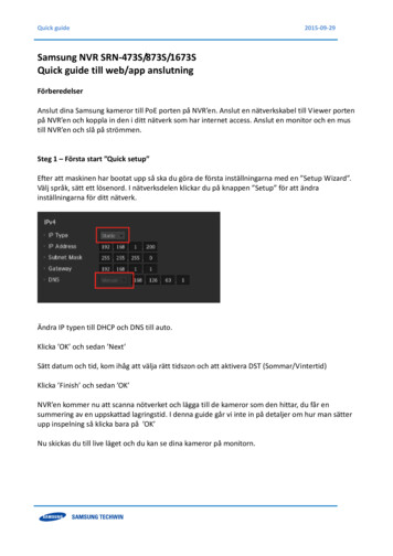
11. Use a sanding block to lightly sand the top of the lower forward fuselageuntil it is flat and even. Then glue on the upper half of each of the threeforward fuselage bulkheads.Test fit the upper forward fuselage sides, trimming and sanding asrequired to get a perfect fit. Note the upper and lower pieces should meetto form a sharp edge to give it that scale Raptor look. Once satisfied withthe fit, glue the upper forward fuselage sides onto the bulkheads and lowerfuselage sides only (don’t glue the aft part to the top of the wing yet). Usetape to hold the sides in place as the glue dries.Page 8
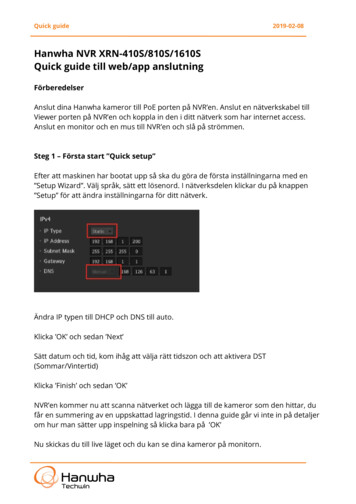
12. Glue bulkheads F4 and F5 to the top of the wing in the locations shown onthe plans. Then glue the aft part of the upper forward fuselage sides to thetop of the wing and the bulkheads. Note how the fuselage sides curveinward as they run aft—you can heat form the foam slightly to attain thiscurvature. Pins can be used to hold the foam in place as the glue cures.Cut the bevel in the two turtledeck support pieces and then glue them inplace on the top inside edges of the fuselage sides. Then glue the twoturtledeck top pieces in place, one at a time so they can be formed to theproper curvature. Once the glue is dry, carve and sand the turtledeckroughly to shape.Install the forward fuselage top (bottom photo).Page 9
13. Laminate all of the nosecone and canopy pieces together using 3M 77adhesive. Then glue the nosecone block to the front of the fuselage.Once the glue has dried, sand the nosecone to shape. Start by tracing thetop outline of the nosecone onto the foam (using the provided template)and cut it to shape with a long knife or saw. Begin with coarse sandpaper(100 grit) to rough out the basic shape, then move to a finer sandpaper(220 grit) to do the final shaping. End with 320 grit sandpaper to do thefinal polish sanding and provide a very smooth surface.Carve the canopy to shape using a similar procedure. Note that clearmolded canopies are available from www.6mmflyrc.com.Page 10
14. Laminate the tail boom pieces together using 3M 77 adhesive. Then gluethe tail boom blocks to the aft fuselage with epoxy. Note that you’ll need tocarve out a small channel in the top of the tail boom blocks first to clear thealuminum stabilator pivot tubes. Make sure the tail boom blocks fit tightagainst the stab pivot tubes, since they provide significant extra strength tothe stabilator pivots.Next carve the tail booms to shape. Note the outboard sides are angled tomatch the aft fuselage sides, the trailing edge is cut at an angle to matchthe trailing edge angle of the stabilators, and the trailing edge is sandeddown to a feathered edge to match the stabilators.Page 11
15. Next install the flaperons. Cut a 45 degree bevel in the leading edge of theflaperons using a ruler and a hobby knife, and then sand the trailing edgesto a tapered shape. Then hinge the flaperons with strips of 3M Gift tapetop and bottom. Trim as necessary to provide a small and parallel gapfrom the leading edge of the stabilators.Install the flaperon servos, control horns, and pushrods. Note thepushrods are angled out slightly to allow locating the control horn in astronger area of the flaperon.Glue the vertical tail support pieces under the wing centered over thevertical tail mounting slots, trimming them if required to clear the flaperonservos.16. Sand the leading edge of the vertical tails to a well-rounded shape, andsand the trailing edges to a tapered shape. Apply a strip of 3M Gift tape tothe leading edge.If installing rudders, cut them free from the vertical tails. Bevel the leadingedges and hinge with strips of 3M Gift tape.Cut the vertical tail mounting slots in the aft wing, making the cut at theproper dihedral angle (use the foam jigs provided as a guide). Cut all theway through the support pieces mounted underneath the wing.Glue the vertical tails in place with epoxy (adding microballons isrecommended), using the foam jig pieces to ensure the proper dihedralangle. Pins can be used to hold the pieces in place as the glue cures.Page 12
17. If incorporating rudders, install the control hardware now. Rudders arenot required, but are helpful for improved control at high alpha and forbetter aerobatics.Mount the servo in a slot on the centerline just aft of the wing spar. UseSullivan micro flexible cable pushrods, with small pieces of 1/32” musicwire soldered onto the rudder end. Use small scraps of foam to supportthe pushrods near the servo as shown, and embed the aft end of thepushrods into a slot the foam in the vertical tail (add epoxy over the slotlater to re-strengthen this area).I used Dubro micro pushrod keepers on the rudder horn and Dubro microEZ connectors on the servo end. Use a 90 degree servo arm and makesure the pushrods connect to the servo arm at a 90 degree angle atneutral (to ensure the rudders deflect equally).Page 13
18. Glue the turtledeck top spine into place on the wing centerline. Then gluethe five turtledeck bulkheads (T1 through T5) into place in the locationsshown on the plans.If you decided to install rudders, note you’ll need to cut a clearance hole inthe top spine to clear the rudder servo. After cutting this hole, glue asmall scrap of 1/64” plywood over the gap as shown in the bottom picture.The plywood will allow the fuselage top piece to sit flat along the entirelength of the spine.Page 14
19. Next shape and install the aft fuselage top piece. This is perhaps the mostchallenging aspect of building this model, so take your time. There aremany ways to form the curvature required, but I’ll describe the particularmethod I used.Begin by cutting all the beveled edges in the aft fuselage top piece asshown on the plans. Next cover most of the bottom of the part withpacking tape (I used yellow packing tape in the top picture at left). Thetape will help keep the piece from wrinkling as you heat form it, and will beremoved when done. Use a heat gun to gently form all the curves asshown in the middle picture. Test fit the piece onto the model as you go todetermine the exact curves required—use the installed turtledeckbulkheads to guide how much and where. There are many ways to heatform the piece, but the method I used was to put the heat gun in a benchvice (to leave both of my hands free), place a large diameter wood dowelon my chest, and then stand in front of the heat gun and roll the fuselagetop piece back and forth across the dowel to form nice gentle curves. Ihighly recommend that you practice this method on some scrap foambefore attempting it on the actual piece! It takes some practice to learn tobend the foam gently without wrinkling it. When done heat forming,remove the packing tape from the bottom of the part.Test fit the piece on the model and trim as required to get a good fit. Thefit should be close but doesn’t have to be perfect, since you can easily usespackling compound later to fill any gaps. When satisfied with the fit, gluethe top piece in place. Use a lightweight, sandable, and gap-filling gluesuch as epoxy with microballons, ProBond, or aliphatic resin. Use lots ofpins and tape to hold the piece in place as the glue dries (bottom photo atleft).After the glue dries, use lightweight spackling compound (available at anyhome improvement store) to fill any gaps and to create large fillets at thejunction with the fuselage turtledeck and at the junction with the wings.After the spackling dries, sand the fillets to shape. Note a thin foamsanding pad works very well for sanding rounded fillets.Page 15
20. Now install the receiver and speed control. There are many ways you cando this, but I chose to install the receiver aft and the speed control near themiddle of the plane with short wire extensions to both the motor and to thebattery in the nose. I used a Berg 7P receiver and a Castle CreationsPhoenix 25 ESC, and highly recommend both. Try to locate everything asfar forward as possible since this model tends to be tail-heavy. Twist allthe ESC wires together to help reduce electromagnetic interference, andtape all wiring down flat against the foam to keep them from floppingaround in flight.NOTE: It’s very important to install the speed control where it will getLOTS of cooling airflow. Mounting it inside the inlets as shown is ideal. Ieven cut away some of the plastic shrink wrap to promote even bettercooling. Cooling is important not just because of the heat generated bythe motor controller, but even more so for the integrated BEC circuitrysince this model requires 5 servos (and most speed controls are only ratedfor 3 or 4 servos). Providing ample cooling to the BEC will allow it operatemore servos safely and help prevent premature shutdowns due tooverheating. Note you could use a separate and more powerful BECcomponent instead, but that would add weight and cost.It’s also recommended to cut cooling holes in the forward fuselage toprovide airflow to the battery (not shown here). Choose a location thatworks best with the particular battery size and shape you use.After everything is installed, test all the controls thoroughly to make sureeverything works properly and that you aren’t getting any majorinterference between components. Once the fuselage bottom is glued on,it will be much more difficult to access all the electronics (you’ll have to cutaccess holes in the foam). I don’t recommend installing any accesshatches at this point—just cut hatches in the foam later as needed if youfind you need to access something.Page 16
21. Laminate the inlet diverter piece and inlet side piece together as shown inthe top photo at left, using 3M 77 adhesive. Make two assemblies. Thenglue the assemblies at the front of the inlets as shown in the bottom photo.Page 17
22. Next make and install the aft fuselage bottom piece. Begin by cutting thebevels in the sides as shown on the plans. Also cut bevels in the exhaustnozzles as shown in the top photo at left. You’ll also need to carve a smallnotch in the center between the exhaust nozzles to provide clearance forthe thrust vectoring pushrod and clevis (test fit the part to determine howmuch clearance is required).Next use a long sanding bar to sand across the bottom edges of thefuselage to make it perfectly flat and straight (middle picture). Test fit thebottom piece and trim as required for a good fit. When satisfied with thefit, glue on the bottom piece. Use a lightweight, sandable, and gap-fillingglue such as epoxy with microballons or ProBond. Use tape to hold thepiece in place as the glue dries (bottom photo).Lastly, glue on the forward fuselage bottom piece (not shown in thephotos).Page 18
23. Now shape the inlets and aft fuselage. Begin by cutting slots in the aftfuselage bottom piece to provide exits for the inlet diverters (see top photoat left). Use a hobby knife inserted between the diverter pieces to cut theslot, and then trim with sandpaper.The leading edges of the inlets can be sanded to a downward slopingangle if desired to improve scale appearance. Just mark lines similar tothose shown in the middle photo at left and then sand down to those lines.Use a sharp hobby knife to trim the inside edges of the inlets to theselines. The final inlets should look something like the bottom photo.Now sand the rest of the aft fuselage to shape. Sand the sides of theinlets down to a sharp edge as shown in the photos, and sand a slightradius on the bottom edges of aft fuselage bottom piece.Final sand the entire model to shape.Page 19
24. OPTIONAL STEP: Because this model has a wide fuselage with angledsides, it can be difficult to get a firm grip for hand launching. To solve thatproblem, I added small fairings on the side of my model. These fairingshighly resemble the landing gear blisters on the real F/A-22 in size andshape, but are a little lower on the fuselage so that your fingers can restjust behind them. They easily blend into the model and are hardlynoticeable, but provide a much improved grip for hand launching.To install these fairings, simply sand them to shape first (sand all sides toa highly feathered shape) and glue in place as shown. Note the front edgeof these fairings are roughly aligned with the indicated CG location (thelight tick mark seen in the photos at left).Page 20
25. CONGRATULATIONS! Your model is now complete.The model can be flown as is or can be painted using standard acrylic craftpaint (available at most craft stores) applied with either a brush or airbrush.Here are a few painting tips: Wipe the entire model with rubbing alcohol before painting to removeall grease and dirt.Rough areas such as the canopy and nosecone should be filled withlightweight wall spackling compound thinned with water, which fills theholes and can be sanded to a very smooth finish with minimal weightgain.Primer isn’t required over Depron, but applying a coat of water-basedpolyurethane (WBPU) will help seal the foam and provide a smootherfinish. Mixing some microballons in with the WBPU will help fill holeseven better and improve the finish further.When thinning acrylic paint for use in an airbrush, thin roughly 50/50with windshield wiper fluid. The wiper fluid will allow the paint to dryfaster (relative to thinning with water), which reduces the chance ofruns. It will not affect the finish.Good luck, and I hope you enjoy this model as much as I have!Page 21
Flight Setup1. Adjust the flight controls to provide the following recommended deflections (all measured at the root trailing edge):Stabilators: /- 1.5" (-40% expo)Ailerons: /- 1.0" (-40% expo)Rudder: /- 0.5" (-20% expo)Thrust vectoring: /- 15 degrees (mixed with elevator)2. For best results, the thrust vectoring servo should be set up to use a simple linear mix with the elevator control. Done properly, fullaft stick should produce 1.5” stabilator deflection and up to 30 deg up thrust vectoring (TV). Ideally this mix should beprogrammed to a switch on your transmitter so that the TV can be turned on and off at will, but it’s OK for the TV to be left on fulltime as well. I recommend starting with 15 degrees of thrust vectoring since it provides amazing maneuverability without makingthe model too pitch sensitive. However, you can go all the way up to 30 deg TV for even more maneuverability—though you’lldefinitely want to be able to turn TV off with a switch since that much deflection will make the model pitch sensitive at high speeds.3. Start with the CG at 3.0” behind the wing root leading edge (see the plans). Depending on the motor and battery you’ve selected,the model may require some ballast in the nose to achieve this. This is a relatively conservative forward CG location, great formaking first flights. You can move the CG aft for more maneuverability later if desired.4. To hand launch this model, grip the airplane near the CG, apply about 60% throttle, and throw it moderately hard straight aheadand slightly nose up. Make sure to keep your hand away from the prop as you throw it! Slowly bring the throttle up as soon asthe model has gained some speed and altitude. It’s important to not launch at full throttle since the torque from the propeller cancause the airplane to roll immediately after launch.5. You’ll find this model is quick on the controls, but well-mannered and easy to fly. With the TV system off it flies very smoothly andwill do large graceful aerobatics, but with the TV system on it will do amazing maneuvers.6. This model handles well at low speeds and is easy to belly land. Fly the approach with a little power to compensate for theincreased drag at high angles of attack, and then flare hard about a foot off the ground. Done properly, the model will do a nicenose-high plop into the grass at very low airspeed. Remember to chop power completely and neutralize the elevator right beforetouchdown, which will protect the propeller and stabilators from damage.Page 22
to form a sharp edge to give it that scale Raptor look. Once satisfied with the fit, glue the upper forward fuselage sides onto the bulkheads and lower fuselage sides only (don't glue the aft part to the top of the wing yet). Use tape to hold the sides in place as the glue dries.