Transcription
(RDBR)redboardbreadboardRedboardBreadboardAssembly Guide(RDBR)
A Few WordsABOUT THIS KITThe overall goal of this kit is fun. Beyond this, the aim is to get youcomfortable using a wide range of electronic components through small, easycircuits. The focus is to get each circuit working then give you the tools tofigure out why. If you encounter any problems, want to ask a question, orwould like to know more about any part, extra help is only an e-mail awayhelp@oomlout.com.ABOUT OPEN SOURCE HARDWAREAll of the projects at SparkFun and .:oomlout:. are open source. What does this mean? It meanseverything involved in making this kit, be it this guide, 3D models, or code, is available for freedownload. But it goes further, you're also free to reproduce and modify any of this material, thendistribute it for yourself. The catch? Quite simple; it is released under a Creative Commons (By - ShareAlike) license. This means you must credit .:oomlout:. in your design and share your developments in asimilar manner. Why? We grew up learning and playing with open source software and the experiencewas good fun, we think it would be lovely if a similar experience was possible with physical things.More details on the Creative Commons CC (By - Share Alike) License can be found athttp://ardx.org/CCLIABOUT .: OOMLOUT :.We’re a plucky little design company focusing on producing“delightfully fun open source products”To check out what we are up tohttp://www.oomlout.comABOUT SPARKFUNSparkFun is an energetic young company seeking to make electronics fun, accessible,and approachable to everyone - from kids in elementary school to PhD-toting engineers.http://www.sparkfun.com/ABOUT PROBLEMSWe strive to deliver the highest level of quality in each and every thing we produce. If you ever find an ambiguousinstruction, a missing piece, or would just like to ask a question, we’ll try our best to help out.help@oomlout.com(we like hearing about problems it helps us improve future versions)Thanks For Choosing .:oomlout:.and SparkFun
.: Where to Find Everything :.TBCNtable of contents{PART}Required Parts02{COMP}Comparing a RDBR to an Arduino USB03{SCEM}RDBR Schematic04{ASEM}Assembly Instructions05{PROG}Programming Instructions08{NOTE}Room to Take Notes0901
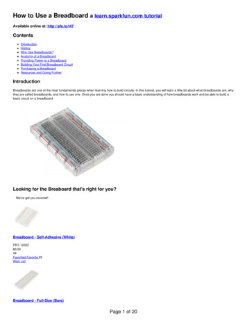
01 PARTthe parts.: The Parts Needed for a :.: Redboard Breadboard :.CapacitorsResistors100 uf - filters the power supply330 ohm (orange-orange-brown)LED current limiting100 nf - bypass capacitor (104)10k ohm (brown-black-orange)Pull-ups22 pf - filters the crystal (220)HeadersBattery Clip - (9v)6 Pin - used for programmingwith an FTDI cable2 Pin - used to pin down thebreadboard layout sheet.For powering the board with a 9vbatteryCrystal - (16 MHz)Provides a clock signal for theATMega chipBreadboardAllows for easy assembly ofcircuits without solderingMicrocontroller -A single chip computer that runsyour codeBreadboard Layout SheetPlace on top of a breadboard toshow where components goVoltage Regulator -(7805)Takes in 7-12 volts and outputs 5voltsPushbutton - (Reset)Resets the micro-controller whenpressed(ATMega328)LEDs-(Light Emitting Diodes)Used as indicatorsRed - powerGreen - connected to pin 1302
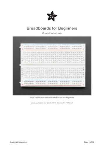
.: An Arduino Uno:.02 COMPcomparison&.: Redboard Breadboard Compared:.03
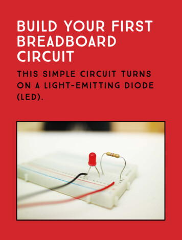
03 SCEM.: Redboard Breadboard:.schematic.:Schematic:.Vin7-12 voltscapacitor100nfcapacitoringndout voltageregulator7805 100ufcapacitor100ufLEDresistor560 ohmprogrammingheaderresistorpower10k ohmpushbuttongndresetctsAtmega328(with Arduino bootloader)Reset5txd0 RXD4resistorrxd1 TXD10k 2pfAnalogVcc3210GNDGND AREFcrystal16MHzcapacitor22pfGnd(-)04Clock 1AVCCClock 21351261171089LEDpin 13resistor560 ohm
04 ASEM.: Redboard Breadboard :.assembly.: Assembly Steps :.Parts:BreadboardLayout sheetx1Breadboardx12 Pin Headerx31Parts:wire330 ohm resistor10k ohm 2x2205
04 ASEMassemblyParts:Capacitor100 ufx2Capacitor100 nf (104)x3Capacitor22 pf (220)x2The 100 uf capacitors are polarized.Put the longer lead in the indicated holethe smoothing capacitors willhave 220 written on themthe decoupling capacitors willhave 104 written on them3Parts:Pushbuttonx106Header (6 pin)x1Red LEDx1Green LEDx14
04 l(16 MHz)x1Voltage Regulator(7805)x1There is a half mooncutout, this goes at the top5Parts:WireBattery Clipx1607
05 PROGprogramming.: Programming Your Redboard Breadboard:.(you can either use an Arduino USB board or anFTDI USB-Serial breakout board to program your RDBR)Using an Arduino USB Boardremove the ATMega chipbefore using as a programmerconnect1. digital 0 - digital 02. digital 1 - digital 13. reset - reset4. 5v - red rail (5v)5. gnd - blue rail (gnd)Using an FTDI Breakout Boarduse the pin labels toline up the adapter(gnd - gnd)08
.: Notes:.:Room for a Few Notes:.06 NOTEnotes09
(RDBR)redboardbreadboardwww.oomlout.comThis work is licenced under the Creative Commons Attribution-ShareAlike 3.0 Unported License. To view a copy of this licence, / or send a letter toCreative Commons, 171 Second Street, Suite 300, San Francisco,California 94105, USA.
your code Voltage Regulator - (7805) Takes in 7-12 volts and outputs 5 volts Breadboard Breadboard Layout Sheet Place on top of a breadboard to show where components go Pushbutton - (Reset) Resets the micro-controller when pressed Allows for easy assembly of circuits without soldering LEDs- (Light Emitting Diodes) Used as indicators Red - power