Transcription
CONTRACT NAS9-9953 MSC\q,92L1DRL NO: MSC-T-575, LINE ITEM 72SD72-SA-0114-3SD 72-SA-0114-3)i MODULARspace stationPHASE B EXTENSIONINFORMATION MANAGEMENT ADVANCEDDEVELOPMlENT FINAL REPORTVolume IlI:Digital Data Bus BreadboardPREPARED BY PROGRAM ENGINEERINGJULY 31, 1972.-(NASACR 12 8 5 6 )INFOR NATION MANAGEMENTADVANCED DEVELOPMENT.VOLurE 3:DIGITALDATA BUS BREADBOARD Final Report C.R.Gerber (North American Rockwell Corp.)31 Jul. 1972187 ph ib-,td1436-N72-33CSCL 22B G3/318Unclas16405',ocsSpace DivisionOil% North American Rockwell1 2 2 1 4L a k e w o o dB o u I e v a r d,D o w n e,C a I i f o r n ia9 0 2 41
CONTRACT NAS9-9953 MSC 02471DRL NO: MSC-T-575, LINE ITEM 72SD 72-SA-01 14-3MODULARspace stationPHASE B EXTENSIONINFORMATION MANAGEMENT ADVANCED DEVELOPMENT FINAL REPORTVolume Ill:Digital Data Bus Breadboard31 JULY 1972PREPARED BY PROGRAM ENGINEERINGApproved by34/Y/S cJames MadewellDirectorSpace Applications ProgramsSpace Division0D 1 2 2 1 4L a k e w o odNorth American RockwellB o u I e v a r d ,D o w n e y ,C a I i f o r n i a9 0 2 4 1
TECHNICAL REPORT INDEX/ABSTRACTACCESSIONNUMBERI DOCUMENT c u ME " T sSECURITYIlITITLEICLASSIFICATIONUNCLASSIFIEDOF DOCUMENTLIBRARYINFORMATION MANAGEMENT ADVANCED DEVELOPMENT FINAL REPORTVolume III, Digital Data Bus BreadboardAUTHORS)Gerber, C. R., et.al.CODEORIGINATINGQN085282PUBLI CATIONAND OTHERSOURCESDOCUMENTSpace Division of North AmericanRockwell Corporation, Downey, CaliforniaDATEJuly 31, 1972DESCRIPTIVEAGENCYCONTRACTNUMBERSD 72-SA-0114-3NUMBERNAS9-9953TERMS*MODULAR SPACE STATION, *INFORMATION MANAGEMENT,*ADVANCED DEVELOPMENT, *DATA ACQUISITION,*DATA BUS, *BREADBOARD, *TECHNOLOGY,*SPECIFICATIONS, *DBCU, *RACUABSTRACTTHIS DOCUMENT IS VOLUME III OF THE FINAL REPORT OF THE MODULAR SPACESTATION ADVANCED DEVELOPMENT STUDY. IT SUMMARIZES THE EFFORT ANDRESULTS OF THE ANALYSIS AND BREADBOARDING OF A DATA ACQUISITION ANDCONTROL SUBASSEMBLY (DACS) TO PROVIDE THE NECESSARY INTERFLOW OFDATA BETWEEN TWO CENTRAL PROCESSORS, SUBSYSTEMS AND EXPERIMENTEQUIPMENT.THE DACS WAS DEFINED TO INCLUDE THE DIGITAL DATA BUS(DDB) THE DATA BUS CONTROL UNIT (BDCU), AND THE REMOTE ACQUISITIONAND CONTROL UNIT (RACU); THE FIRST TWO OF THESE WERE ANALYZED ANDBREADBOARDED AS A PART OF THE EFFORT. THE PRIMARY OBJECTIVE OF THEDACS BREADBOARD IS TO VERIFY THE DIGITAL DATA BUS CONCEPT FOR THEMODULAR SPACE STATION.IT DEMONSTRATES THE AVAILABILITY OF TECHNOLOGYTO PROVIDE ACCURACY OF DATA TRANSFER, RECONFIGURABILITY, FAILURETOLERANCE, LONG USEFUL LIFE, AND STANDARDIZATION OF INTERFACES.I,IIFORM M 131-V REV. 1-68USE ONLY
'% Space DivisionNorth American RockwellFOREWORDThis document is one of a series required by Contract NAS9-9953,Exhibit C, Statement of Work for the Phase B Extension - Modular SpaceStation Program Definition. It has been prepared by the Space Division,North American Rockwell Corporation, and is submitted to the National Aeronautics and Space Administration's Manned Spacecraft Center, Houston, Texas,in accordance with the requirements of the Data Requirements List (DRL)MSC-T-575, Line Item 72.This document is Volume III of the Modular Space Station InformationManagement System Advanced Development Technology Report, which has beenprepared in the following six volumes:IIIIIIIVVIMS ADT SummarySD72-SA-0114-1IMS ADT Communications TerminalBreadboardSD72-SA-0114-2IMS ADT Digital Data Bus BreadboardSD72-SA-0114-3IMS ADT Data Processing AssemblySD72-SA-0114-4IMS ADT Software AssemblySD72-SA-0114-5-iii-SD 72-SA-0114-3
9i Space DivisionNorth American RockwellACKNOWLEDGEMENTSThe following persons have participated in the conduct of the IMSADT tasks, and have contributed to this report:C.C.B.E.D.V.W. RobertsR. GerberA. Logan, Jr.MehrbachW. BrewerR. HodgsonExperiment/Electronics ManagerInformation Systems Project EngineerInformation SystemsInformation SystemsInformation SystemsInformation SystemsThe following subcontractors have supported the IMS ADT tasks inspecialized areas:International Tel. & TelNutley, New JerseyB. Cooper, Proj. Mgr.Communications Terminal B.B.Data Bus BBIntermetricsCambridge, Mass.J. Miller, Prog. Mgr.Data Processing AssySystem Develop. CorpSanta Monica, Calif.R. Bilek, Prog. Mrg.Data Processing AssySoftware AssyGen'l Electric Corp.Valley Forge, Pa.R. Kirby, Prog. Mgr.Bulk Storage TechnologyNR-AutoneticsAnaheim, Calif.J. Jurison, Proj. Mgr.Data Bus BBData Processing AssyPreceding page blankPRECmEDING PAX BLANK NOT FILMEDSD 72-SA-0114-3
9 Space DivisionNorth Amencan RockwellCONTENTSPageSectionI.INTRODUCTION.I.I DACS REQUIREMENTS SUMMARY1.2 DACS BREADBOARD DESIGN.2.PARAMETRIC DATA FOR BUS DESIGN2.1DIGITAL BUS.2.2 ANALOG BUS2.3 COUPLING CONFIGURATION2.4 CONCLUSIONS AND RECOMMENDATIONS3.DACS MODEL CONFIGURATION .3.1 INTRODUCTION AND SUMMARY3.2.6.2-12-12-42-42-7. 3-1. 3-1. 3- I1. 4-1DACS REDUNDANCY CONCEPTS .4.1INTRODUCTION AND SUMMARY OF4.24.3. 4-2SUBSYSTEM MODELS AND CONFIGURATIONSDACS REDUNDANCY AND RELIABILITY CONCEPTS . 4-74.4DACS RECOMMENDATIONS. 4-1REDUNDANCY REQUIREMENTS5. I-I. I-I. 1-3RECOMMENDED DACS BREADBOARDCONFIGURATION.4. 4-34DACS BREADBOARD DESIGN REQUIREMENTS .5.1 GENERAL REQUIREMENTS.5.2 BREADBOARD DESIGN REQUIREMENTS. 5-1. 5-1. 5-2DATA BUS BREADBOARD PERFORMANCE AND.INTERFACE REQUIREMENTS6.1 GENERAL REQUIREMENTS.6.2 BREADBOARD DESIGN REQUIREMENTS. 6-1. 6-1. 6-2Preceding page blankPRECIDING PAGE BLANK NOT FILMED-VIISD 72-SA-0114-3
'Space DivisionNorth American RockwellPageSection7DBCU BREADBOARD PERFORMANCE AND INTERFACEREQUIREMENTS.7.1 ITEM DEFINITION7.2 FUNCTIONAL DESCRIPTION7.3 INTERFACE DEFINITION7.4 PERFORMANCE87.5PHYSICAL CHARACTERISTICS.7.6ENVIRONMENTAL.7-247-26DIGITAL DATA BUS DESIGN .8.1 SYSTEM T PERFORMANCESPECIFICATIONS.DBCU DESIGN .9.1 PHYSICAL DESCRIPTION9.2 CONTROLS AND DISPLAYS.9.3 BASIC OPERATION8-49-19-19-29-9.APPENDIX A PRELIMINARY DACS BREADBOARDLAYOUTA-I.- Viii -SD 72-SA-0114-3
Space 1-21-31-4DACS Work Breakdown and FlowRecommended DACS ConfigurationFunctional Relationship of Breadboard ElementsDual Redundant DACS Breadboard1-21-41-61-72-12-22-32-4Digital Data Bus, First ConfigurationDigital Data Bus, Second ConfigurationMethods of CouplingDirect and Transformer Coupling with T-Pads2-22-32-52-63-1Data Management Subsystem EEM Growth 04-114-124-13Non-critical Subsystem Functional Loop Models .Non-Time Critical Subsystem Functional Loop ModelsTime-Critical Subsystem Functional Loop Models .Candidate DB-I, Four Simplex Data Bus SubassembliesCandidate DB-2, Two Dual Redundant Data BusAssembliesCandidate DB-3, One Quad Redundant Data BusAssembly*Candidate R-l, RACU with Simplex Data Bus InterfaceCandidate R-2, RACU with Dual Data Bus InterfaceCandidate R-3, RACU with Quad Data Bus InterfaceCandidate CU-I, Single IOP Simplex DBCUCandidate CU-2A, Dual IOP Simplex DBCUCandidate CU-2B, Dual IOP Single Failure Tolerance DBCU ·.Recommended DACS Configuration5-15-25-3Message Formats .Breadboard Modem Unit Functional InterfaceBreadboard External Test Function Interface5-85-155-196-16-2Bi-Phase Level Data Encoding .Uni-directional Equipment/Bi-directional Core6-66-124-6- ix -SD el
'Space DivisionNorthAmerican Rodwell rFigurePage7-17-2Functional Relationship of Various Breadboard ElementsDBCU/MODEM Interface7-27-37-3DBCU/MODEM Interface Timing Diagram .7-67-47-57-67-77-87-9BIO/DBCU Interface.BIO/DBCU Timing DiagramDBCU/STE InterfaceDBCU Functional OrganizationDBCU/RACU Message FormatsTransmission Code Formats8-18-2Skeleton Diagram of Data Bus SystemBreadboard Configuration, Block Diagram8-38-4Coupler, Schematic Diagram .Receive Clock Tolerance.8-5Attenuation vs. Frequency for RG-22B/J Cable .8-119-19-29-39-49-59-6DBCU Front PanelTape Reader/Power Unit - Front PanelCompareSet Mode of OperationsDBCU/RACU Data TransferBIO/RACU Data Transfer9-39-109-129-139-149-159-7BIO/DBCU Data Transfer9-169-89-9Status Word.DBCU Data .TABLESTablePage4-2Number of RACU's Per Subsystem Functional LoopModel for the Seven RACU CandidatesMinimum Number of Candidate Data Bus Control4-3Units.DACS Element Candidates7-1Universal and Group Address Codes4-1.4-244-324-33x.-SD 72-SA-0114-37-22
Space DivisionNorth American RockwellABBREVIATIONSADSADTADTXAFCAGCANAdvanced Data SystemAdvanced Development TechnologyAdvanced Development Technology ExtensionAutomatic Frequency ControlAutomatic Gain ControlAutonetics (Division of North AmericanRockwell Corporation)BPFbpsBandpass FilterBits Per SecondCAIRSCPT&ECRCRTCSSCTBCTFComputer-Assisted Interactive ResourceSchedulingInternational Radio Consultative CommitteeCritical Design ReviewContract End ItemComputer Language for Aeronautics andSpace ProgrammingCommand Module (Apollo)Common Pool (of Data)Central Processor or Circular PolarizationComputer ProgramComputer Program Contract End ItemComputer Program Configuration ItemComputer Program Development FacilityComputer Program Integration Contractor(Agency)Computer Programming Test and EvaluationChange ReportCathode-Ray Tube (Display)Crew SubsystemCommunications Terminal BreadboardCentral Test ata Acquisition and Control SubassemblyDecibelData Bus Control UnitDecibel Referred to One Milli-WattDecibel Referred to One WattDesign Change RequestDigital Data BusDe-Multiplex(er)Data Management SystemData Processing AssemblyDual Phase Shift KeyingData Relay Satellite PIC (A)- xi SD 72-SA-0114-3
Space DivisionNorth American RockwellECPEDFEEMEEMPEIRPEMCEMIEOSEOSSEPSETC/LSS or ECLSSEVAEXTEb/NoEngineering Change ProposalExperiment Data FacilityEngineering Evaluation ModelEngineering Evaluation Model ProcessorEffective Isotropic Radiated PowerElectromagnetic CompatabilityElectromagnetic InterferenceEarth Orbital ShuttleEarth Orbital Space StationElectrical Power SubsystemEnvironment Control and Life SupportSubsystemExtra-Vehicular ActivityExternalEnergy Per Bit to Noise Density RatioFACGSFDMFMFQTFacsimileFrequency-Division MultiplexFrequency ModulationFormal Oualification TestG&CSGFEGHzGOAGuidance and Control SubsystemGovernment Furnished EquipmentGiga-HertzGated Operational AmplifierHALHOLHOLMHzHigher-Order Aerospace Programming LanguageHigher-Order LanguageHigher-Order Language SS or IMS/SITTK-wordsK-EAPSK-bpsKHzIntermediate FrequencyIn-Flight Replaceable UnitIntermodulation ProductsInformation Management SystemInformation Management SimulationInitial Operational CapabilityInput-Output Control BlockInput-Output UnitInput-OutputIntermediate Power AmplifierInteractive Query LanguageInfra-RedInformation (Management) Subsystem.International Telephone and TelegraphThousands of (Computer) WordsThousands of Equivalent-Add OperationsPer SecondThousands of Bits Per SecondKilohertz-xii-SD 72-SA-0114-3
Space DivisionNorth American RockwellLEMLMLNALOLPFLunar Excursion ModuleLunar ModuleLow Noise AmplifierLocal OscillatorLow Pass FilterM1, M2MbpsMCBMHzMOFMOLMSCMSFNMSSMUXmWMWmV(Computer) Memory DesignationMegabits Per SecondModule Control BlockMegahertzMission Operations FacilityManned Orbiting LaboratoryManned Spacecraft lenterManned Space Flight NetworkModular Space FNoise FigureOBCOOCCODMOMOn-Board CheckoutOperations Control Center (On-Board)Operational Data ManagementOperating MemoryPAPCMPDRPL/1PMPN (PRN)ppmPOTPSKPower AmplifierPulse Code ModulationPreliminary Design ReviewProcedure LanguagePhase ModulationPseudo Random NoiseParts Per MillionPreliminary Oualification TestsPhase Shift KeyingRANMRACURCSRFRHCPRPURxResearch and Applications ModuleRemote Acquisition and Control UnitReaction Control SubsystemRadio FrequencyRight-Hand Circular PolarizationRemote Processing UnitReceiveS&CSCCBSCNSDStandards and ConventionsSoftware Configuration Control BoardSpecification Change NoticeSpace Division (of North American RockwellCorporation)Systems Development CorporationSDC- xiii SD 72-SA-0114-3
Space DivisionNorth American RockwellS/NSOWSPLSRDSSCBSSSSTESignal to Noise RatioStatement of WorkSpace Programming LanguageStep-Recovery DiodeSolid-State Circuit-BreakerStructures SubsystemSupport Test EquipmentTAVTBDTCXOTDATDMTDRSTIPTLM, TMTOOLTRWTT&CTWTTWTATxTest and Validation (Programs)To Be DeterminedTemperature-Controlled Crystal OscillatorTunnel Diode AmplifierTime Division MultiplexingTracking and Data Relay SatelliteTest and Integration PlanTelemetryTest Operations Oriented LanguageThompson Ramo Woolridge CorporationTelemetry, Tracking and ControlTraveling Wave TubeTraveling Wave Tube AmplifierTransmitUSB (E)UVUnified S-Band (Equipment)Ultra-VioletVDDVHFVSBVSWRVersion Description DocumentVery High FrequencyVestigal Side BandVoltage Standing Wave Ratio- xiv SD 72-SA-0114-3
OT4 North American Rocl wellLIST OF INTERIM REPORTSAA-101DPA Flow Diagrams, September 1971AA-102DPA Throughput and Authority Analysis,February 1972AA-103DPA Configuration Selection, April 1972AS-101Modular Space Station Computer ProgramStandards and Conventions, December 1971AS-102Modular Space Station Computer ProgramSpecification Tree, February 1972AS-103Modular Space Station Computer ProgramDevelopment, Test and ConfigurationControl Plan, May 1972AS-104Modular Space Station Computer-AssistedResource Allocations and UtilizationRecommendations, June 1972CTB-101Concepts for Multiple RF LinkMechanization, May 1971CTB-103Antenna-Mounted Electronics ComponentDesign, October 1971CTB-105/106CTB Integration and Test and OperationsManual, June 1972DB-101Parametric Data for Bus Design, May 1971DB-103Component Performance Requirements,Schematics and Layout Drawings,December 1971DB-104Digital Data Bus Breadboard Final Report,May 1972DD-102Modular Space Station Data ProcessingAssembly Parametric Evaluation ofSubsystems Input/Output Interface,June 1971xv -SD 72-SA-0114-3
9DSpace DivisionNorth American RockwellDD-103Modular Space Station Data Acquisitionand Control Subassembly Model Configuration(SD 71-233), July 1971DP-101Data Processing Assembly Configuration(Preliminary), June 1971DP-102Data Processing Assembly SupervisorSpecification, May 1972DP-103DPA Processor Performance Requirements(Preliminary), August 1971DP-103DPA Processor Final Description, May 1972DP-104EEM DMS Processor Development Plan, June 1972DP-105Data Acquisition and Control RedundancyConcepts, August 1971DP-106Application of Redundancy Concepts toDPA, January 1971DP-107Data Acquisition and Control SubassemblyBreadboard Design Requirements, October 1971DP-108Data Bus Control Unit PerformanceRequirements, January 1972DP-109Data Bus Control Design Reports, March 1971DP-110DBCU Acceptance Report (to be published)EL-277Bulk Storage Development PlanIB-101DPA Internal Flow and Traffic Pattern,May 28, 1971ICD #TRW 20549Interface Control Document - Data BusModem/RACU, Revision A, January 17, 1972ICD #AN 26465Interface Control Document - Data BusController Unit to Buffer I/O, RevisionJanuary 21, 1972MD-101Mass Memory Parametric DataRF-101Modular Space Station CommunicationsTerminal Breadboard Preliminary SystemSpecification, October 1971- xvi SD 72-SA-0114-3
Space Division91North American RockwellSA-101Central Processor Operational Analysis,September 30, 1971SA-102Central Processor Memory Organization andInternal Bus Design, December 30, 1971SD 71-227Automatic Control and Onboard CheckoutFinal Study Report- xyii-SD 72-SA-0114-3
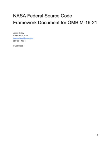
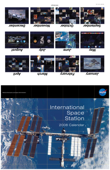
9, Space DivisionAd4 North American Rockwell1.1.1INTRODUCTIONDACS REQUIREMENTS SUMMARYIn the Modular Space Station the Data Processing Assembly (DPA) ishighly distributed. The concept of two pressure volumes results in thedivision of the central processor in such a way that the computationsassociated with station operations and experiments can be performed ineither volume. Similarly, the subsystems and experiments are dividedbetween the two pressure volumes and, what is more, the subsystems aredistributed throughout the modules that make up a 6-man or a 12-man configuration. Some of these subsystems require "on-the-spot" computations;these are provided in the DPA design by remote processing units (RPU's).All subsystems require computational support from the Data ProcessingAssembly. Therefore the DPA must acquire data from these distributedsubsystems and return data, instructions and commands.A significant portion of the ADT effort has been devoted to theanalysis and breadboarding of a data acquisition and control subassembly(DACS) to provide the necessary interflow of data between the two centralprocessors, the subsystems and the experiment equipment. The DACS has beendefined to include the Digital Data Bus (DDB), the Data Bus Control Unit(DBCU), and the Remote Acquisition and Control Unit (RACU). Two of thesehave been analyzed and breadboarded as a part of the ADT effort; these arethe DBCU and the DDB.Figure 1-1 presents the task breakdown and flow which was followedin ultimately delivering breadboards of the DBCU and the DDB. Note thata RACU/RPU breadboard is GFE.The data acquisition and control analyses began with a theoreticalanalysis of the parameters pertinent to the design and usage of data buses.The result of this analysis was a "design handbook" covering the significantaspect of wideband digital and analog data buses.Then a model was defined for the Data Acquisiton and Control Subassembly(DACS) breadboard. The purpose of this definition was provide data to serveas a basis for the design of a DACS breadboard. It identifies the objectivesof the breadboard, some potential vehicle related problems, and a simplifiedimplementation concept.The primarydata bus conceptthe availabilityfigurability,of interfaces.objective of the DACS breadboard is to verify the digitalfor the Modular Space Station (MSS). It shall demonstrateof technology to provide accuratedata transfer, reconfailure tolerance, long life and standardization1-1SD 72-SA-0114-3
II!iIit&tIIIIIFigure 1-1.9DACS Work Breakdown and Flow1-2.-,:I.Pit'*M. . '-EfJ- U;E1'.Space DivisionNorth American Rockwell#SD 72-SA-0114-3D4.i-!-4'3
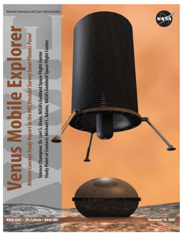
1% Space DivisionNorth American RockwellThe analysis of DACS redundancy concepts covers the advantages anddisadvantages of a general range of concepts and methods applicable tothe DACS. Recommendations of methods were made and justified.The overriding requirements were found to be the single and triplefailure tolerance requirements and the physical separation of redundantsubsystems into pressure isolatable volumes.The recommendations for the degree, level and type of redundancyfor each DACS element are presented. These recommendations include thesplit between hardware and/or software techniques, the utilization oferror protection coding, the replacement/repair methods and a definitionof the replaceable items, and the rationale for each selected candidateDACS element.The following redundancy requirements were imposed on the stationsubsystems1.A capability must be provided for each non-critical functionto fail safe for the first failure.2.For a critical function a capability must be provided for:3.A.Full operation subsequent to a first failure (fail operational)B.Reduced or "out of spec" performance subsequent to a secondfailure (fail degrade).C.Crew survival for at least 96 hours subsequent to a thirdfailure (fail emergency)Time critical functions require active (on-line continuous operation) redundancy. Non-time critical functions require at leaststandby (wired in and can be placed in operation with automaticor manual switchover.Figure 1-2 presents the recommended implementation of the DACS so thatit will satisfy the failure criteria (redundancy requirements).1.2DACS BREADBOARD DESIGNThe DACS breadboard is an engineering model that is representative of theconcepts for the data acquisition and control function of the data processingassembly of the modular space station. The NASA defines a breadboard as a unitwhich performs the same functions and according to the same characteristics asthose defined by the hardware design.A data acquisition and control subsystem is a semiautonomous subsystemthat provides controlled communication between a large number of remote locations and a control location. Insofar as possible, the DACS breadboard is arepresentation of such a subsystem. The DACS breadboard also provides a testbed for operational performance evaluation of numerous concepts for this typeof subsystem oriented toward the specific needs and requirements imposed bythe modular space station.1-3SD 72-SA-0114-3
-41-4UF-4HFUi,.,JSpace Division:DUPin.Hado9ou'r-,c.:joOTI% North American RockwellinV(SD 72-SA-0114-3
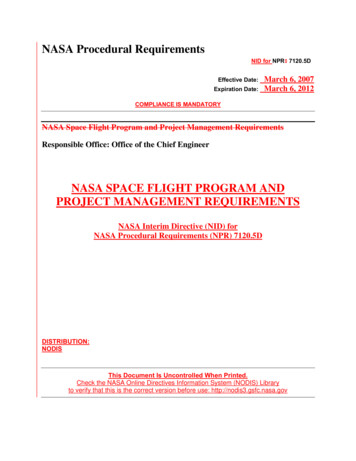
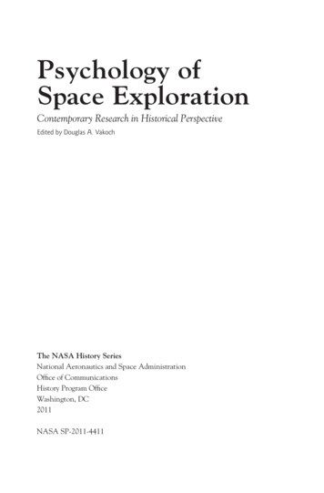
04 North American RockwellSpace DivisionThe overall breadboard concept for the DACS is a highly flexible,configuration independent, building block approach. This approach allowsa large number of different DACS configurations to be assembled as an operating data acquisition and control subsystem breadboard. Each configurationconcept can then be operated, tested and evaluated for overall DACS conceptand performance valuation.The DACS breadboard is an engineering model but is representative of theconcepts for the data acquisition and control subassembly for the data processing assembly of the modular space station.The communication spine for the DACS breadboard is provided by thedata bus breadboard. All communication between the breadboard remoteacquisition and control units (RACU's) and the data bus control unit (DBCU)utilize the data bus breadboard. This communication is also controlled bythese other DACS breadboard units.The data bus controller unit (DBCU) is one item of the major elementswhich make-up the modular space station (MSS) data processing assembly. Thefunctional relationships of the various elements of the DACS breadboard equipments are shown in Figure 1-3. Direct interfacing elements with the breadboardDBCU include the test processor, test panel and special test equipment, MODEM,and prime power source.The DBCU breadboard performs as an input/output device for the testprocessor, controls the information flow on the data bus, and performsthe following functions:a.Provides all command and control capabilities to fully exercisethe DACS breadboard, to communicate with the RACU breadboardsvia the breadboard MODEM units and data bus, and to operatethe breadboard with or without the use of the test processor.b.Provides the capabilities to initiate all read/write actions withthe test processor or test panel interfaces.c.Provides the buffering and formatting of all input/output data tothe test processor, test panel, or data bus interfaces.d.Provides the capability for error protective encoding and checkingof all data to and from the test processor or data bus as selectedby the test panel.Figure1-3 indicates all of the components of the DACS breadboard,however, not all of those shown are part of the ADT effort. The others areGFE. Note in particular, that there are enough DDB components to configurea dual redundant data bus. It will be possible with this breadboard, then,to evaluate wideband digital data bus operation (10 Mbps), automatic faultdetection and isolation, automatic reconfiguration, techniques for executivecontrol of data traffic, etc.1-5SD 72-SA-0114 -3
zFZ)0I -J,DU-CN1-6ZILIezI-CSpace DivisionI'v-I0fX4 '-CdciXarlC-i,zrd0o0North American Rockwell0CLZ ,14fez 4-) Z9TiZ,0mzN--ZenjF-USD 72-SA-0114-3
Space DivisionAftNorth American RockwellThe requirements for the DACS breadboard itself and for its components,in particular, the DBCU breadboard and the data bus breadboard, are presentedin specification format, Sections 5.0, 6.0, and 7.0. For this reason, thereader will notice some repitition in these sections. Furthermore, therequirements definition process was iterative and dependent upon the resultsof the supporting studies (Sections 2.0, 3.0, and 4.0), as well as the resultsof the simultaneous MSS Phase B studies. Hence, there may appear to be discrepancies in some of the numerical parameters used in specifying the breadboard requirements. For example, one parameter which varied with the progressof the Phase B study was the line lengths imposed by the modular configuration.1-7SD 72-SA-0114-3
Division004 SpaceNorth American Rockwell2.0PARAMETRIC DATA FOR BUS DESIGNThe data acquisition and control analyses began with a theoreticalanalysis of the parameters pertinent to the design and usage of data buses:.The result of this analysis was a "design handbook" covering the significantaspect of wideband digital and analog data buses2.1DIGITAL BUSTwo basic digital bus configurations, outlined below, were analyzedalthough within both there are variations.The first configuration shown in simplified form in Figure 2-1 consistsof a core bus located in the core and a module bus located in each module.Both buses are bi-directional, therefore requiring bus enabling signals fortime multiplexing digital signals and preventing ringing in bus couplingdrivers and receivers.The amplifiers are located at the module-core interface for isolation,and circuit drive requirements.The second configuration shown in simplified form in Figure 2-2 retainsthe bi-directional core bus and provides directional module buses. Thisapproach has the possibility of:* Eliminating the module bus enable signals, thus saving equipment· Improving the reliability of the system be eliminating theenable signal and by spreading the equipment loads over twobuses instead of one· Eliminating the necessity of designing an enable bus control· Providing a reduction in spare parts· Costing the same as the other approachThe approach to both basic configurations were selected because they:· Allow checkout operations of individual modules· Allow the MSS to go through a buildup sequence withoutbus modificationAllow more reliable operations because the core bus is passiveand the module buses are independent of each other.The above approach is known as a spreaded star configuration due to the corelength. A circular configuration with the bus looped in and out of each2-1SD 72-SA-0114-3
2-2IId) 0n North American RockwellSpace Division9 Ifl co.oCoU,;UoIGHi.1mo L.SD 72-SA-0114-3
coiIzLULLUU j 2- 32-9 North American RockwellSpace DivisionIII'30 -0 -SD 72-SA-0114-30UUo
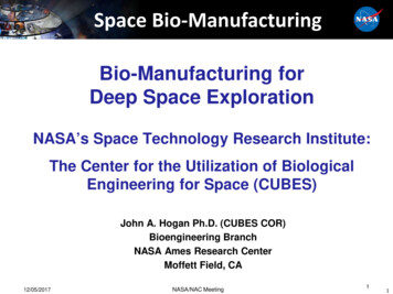
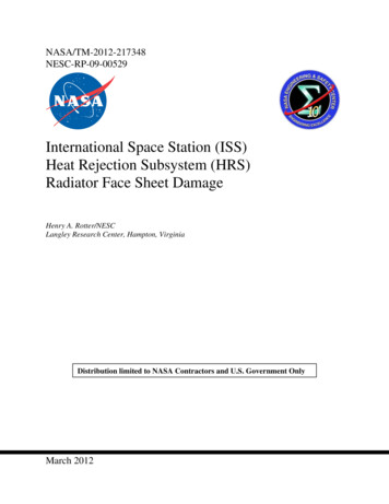
9Space DivisionNorth American Rockwellmodule was examined but was discarded because of the problems it presentedin reliability buildup sequence and module self check.2.2ANALOG BUSThe analog bus is different from the digital bus in that the formeris FDM and the latter is TDM. For this reason, the audio could best employthe configuration shown in Figure 2-2, exceDt that there is no equipmentenable (not required for FDM).2.3COUPLING CONFIGURATIONFor digital and analog buses, both direct and transformer couplingtechniques with surge protection were considered to interface the busseswith their terminal devices and to interconnect sections of the bus.2.3.1Digital BusThe following were investigated for the diRital bus (see Figure 2-3):. Direct coupling using off-the-shelf IC's. Transformer coupling using H-pad with shunt transformer. Transformer coupling using series transformer without paddingTwo other methods are apparent and dual to choices two and three, and theyare:. Transformer coupling using O-pad with series transformerTransformer coupling using shunt transformer without paddingThe latter two methods were not examined because the padded series transformeris a dual of the padded shunt transformer and doesn't require a separateanalysis and because, for the unpadded shunt transformer. sufficiently highimpedance cannot be realized at 10 mbs. The data rate above which the unpaddedshunt transformer becomes unrealizable lies somewhere between 10 and 100 kbs.2.3.2Analog BusThe following were investigated for the analog bus (see Figure 2-4):· Direct coupling using T-pads* Transformer coupling using T-pads with shunt transformer2-4SD 72-SA-0114-3
Space DivisionNorth American RockwellOdd1Dl\RECTCOUIPANGSZk)HT TFAKSFORMVER COUP\UNWl74kiHPADU hl-0E lSZ\ISS E R\EtMP0NSFORMER5COUP\IN4 UNPADDEDRANS 0 R YER W 1w 44mT)UN1TTRFA3FigureMopmeR CouiiN2-3. lUHMethods of Coupling2-5SD 72-SA-0114-3
DivisionOD SpaceNorth American RockwellwI.,,-- --- - -,II-ThDIRECT COUPLING WITH T PADSTRANSFORMER COUPLING WITH T PADSFigure 2-4. Direct and Transformer Coupling with T-Pads2-6SD 72-SA-0114-3
9 ,Space Divisionby4 North American Rockwell2.4CONCLUSIONS AND RECOMMENDATIONSThe conclusions are as follows:Configuration - The digital and audio bus should employ the sameconfiguration: that is, the two-bus concept with bidirectional core busand directional module buses (See Figure 2-2).Coupling - The digital bus should employ transformer coupling: thatis, the H-pad with shunt transformer. The analog bus should employ transformer coupling with a shunt transformer in a T-pad.2-7SD 72-SA-0114-3
Space DivisionNorth American Rockwell3.03.1DACS MODEL CONFIGURATIONINTRODUCTION AND SUMMARYThe initial effort of the DACS BB study was to define a model for theData Acquisition and Control Subassembly (DACS) breadboard. The purpose ofthis definition was to provide data to serve as a basis for the design studiesof a DACS breadboard. This data was used, primarily as an input to WBS85710-7, DACS Model Design, and WES 94009-2, Data Bus Breadboard Design.This section presents the recommended DACS breadboard system definition.It identifies the objectives of the breadboard, some potential vehicle relateddesign problems, and a simplified implementation concept.3.2RECOMMENDED DACS BREADBOARD CONFIGURATION3.2.1Objective of DACS BreadboardThe primary objective of the DACS breadbroad is to verify the digital
This document is Volume III of the Modular Space Station Information Management System Advanced Development Technology Report, which has been prepared in the following six volumes: IMS ADT Summary IMS ADT Communications Terminal Breadboard IMS ADT Digital Data Bus Breadboard IMS ADT Data Processing Assembly IMS ADT Software Assembly SD72-SA-0114-1