Transcription
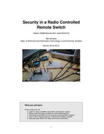
Security in a Radio ControlledRemote SwitchProject 3, EDA625 Security, 2016 Issued 2016-01-03Ben SmeetsDept. of Electrical and Information Technology, Lund University, SwedenVersion 2016-02-21What you will learnIn this project you will Learn to setup a 433Mhz transmitter and receiver module Study a communication protocol to control light switches Use Arduino controllers for the receiver and transmitter modules Learn how to improve security in the communication protocol Intercept radio traffic from Nexa and Proove controllers1
Security in a Radio Controlled Remote SwitchCONTENTSContents1 Instruction1.1 Checklist . . . . . . . . . . . . . . . . . . . . . . . . . . . . . . . . . . . . . . . . . . .332 Introduction43 Communication and Protocol54 Building and testing the remote controller4.1 Building . . . . . . . . . . . . . . . . . . . . . . . . . . . . . . . . . . . . . . . . . . .4.2 Testing . . . . . . . . . . . . . . . . . . . . . . . . . . . . . . . . . . . . . . . . . . . .7775 Building and testing the receiver5.1 Building . . . . . . . . . . . . . . . . . . . . . . . . . . . . . . . . . . . . . . . . . . .5.2 Testing . . . . . . . . . . . . . . . . . . . . . . . . . . . . . . . . . . . . . . . . . . . .8886 Reflections97 A secure Nexa98 Arduino environment8.1 Tracing output . . . . . . . . . . . . . . . . . . . . . . . . . . . . . . . . . . . . . . . .10109 Receiver and Transmitter module1110 What to do what it doesn’t work1111 A receiver and transmitter using one Arduino1212 Approval sheet142
Security in a Radio Controlled Remote Switch1InstructionInstructionYou meet in the project description a number of assignments. These assignments guide your workand you should use the assignments to structure your project work and your report. Give clear indications where you put your answers to the specific assignments (e.g. in yourreport refer to original Assignment and question numbers in this document). For convenience name the report Project3 eda625xyz, where xyz corresponds to your STIL id. You should submit the reports electronically in pdf or word format and use the subject "EDA625"in the email that contains the report. Send it to ben.smeets.lu@analys.urkund.se.DO READ this entire document before it starts.AT HOME you should make the circuit drawings how to connect the receiver and transmitter unitsto the Arduino boards. Compute the length of the antenna, you find the formula in the section thatdescribes the TX/RX modules. Your drawings and computation will be checked and must be approvedby the assistant before you can switch on the equipment.BEFORE YOU ASK HELP follow the instructions that go along with the assignments. Check the wiringof your circuit.1.1ChecklistYou should submitItem123456DescriptionReport with your names on itCircuit TX/Arduin0 1 in reportCircuit RX/Arduino 2 in reportSource code TX in reportSource code RX in reportScanned approval sheet (see end of this document)included in report3
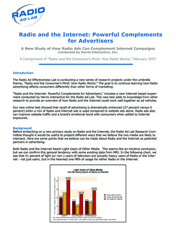
Security in a Radio Controlled Remote Switch2IntroductionIntroductionIncreasingly we automate functions in our homes. Turning on or off lamps and electronic equipmenthas been possible already for many years using radio controlled switches. Typically the user buysone or several switches which can be controlled via a handheld remote. These remotes can be verysimple or can be programmable, see Figure 1. The units in Figure 1 are relatively cheap and use433Mhz radio technology to send signals from the remote to the receivers in the switches. In recentyears the remotes have been complemented with computerized controls that allow people to programthe control via a web interface and get status data from other units like temperature or door sensors.Such systems can then be made into a simple smart home system that allows one to control lightsand heating on the basis of programmed time schedule or external stimuli.There are several types of such systems offered today on the market and in this project we will havea look at one of the simpler ones that can are sold under different brand names. Here we look onlyand the Proove and Nexa self learning switches like shown in Figure 1. These self learning switchescan be put into a state in which they learn the codes send by a remote. In older systems remotes andswitches had to be paired, often using small dip-switches.In this project we will study the protocol used to control the light switches with the purpose to understand how secure the protocol is. We will see that there is room for a lot of improvement in securityand this is also one of the goals of this project. What simple improvements one can make the protocolmore secure. In the real world the security problems are a concern when we really want to have suchsystems for home automation. We therefore already see better solutions coming on the market usingmore advanced standardized technologies for low energy communication for Internet-of-Things (IoT)applications. We notably have here WirelessHart, Zigbee and Z-wave.Yet it is instructive too look at the simpler systems to understand the principles. Instead of using anexisting remote we will develop a simple remote by taking an Arduino controller and a simple 433Mhztransmitter. We program the controller to perform a simple on-off cycle of a commercial Nexia/Prooveself-learning switch. Next we build a dummy receiver using a second Arduino controller. This allowsus later to simulate our security improved switch. This setup avoids us having to find out how toreprogram the commercial Nexia/Proove switches which might have been hard but also require toopen and modify a device that is to be used on a 230v system with all its safety implications. In thethird part of the project you have to make changes in the way the protocol works so it becomes moresecure. Here you can apply the knowledge of what you learned in the course, e.g. encryption of datatraffic.While working on this project you have to answer a number of assignments. These must be answeredand they are intended to give you some guidance. You are free to explore more than what theseassignments ask you to do.Figure 1: Example of two remotes and a self-learning switch of a 433Mhz system.4
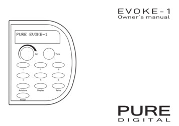
Security in a Radio Controlled Remote Switch3Communication and ProtocolCommunication and ProtocolThe communication from the controller to the receiver in the switch is very simple. We follow herethe analysis by Joakim Wesslen in [1]. The protocol is using On/Off-Keying of the transmitter to sendsymbol 0’s and 1’s. By changing the timing in the on-off pattern one distinguishes between a one andzero. Fig 2 shows the timing where the time constant T 250µsec long. There are beside the 0 and1 symbols two other symbols, the "sync" and the "pause". We refer to the symbols in Fig 2 as thephysical symbols. Using these symbols we encode all logical data. Each logical data is sent as twoFigure 2: Encoding of 0’s and 1’s into On-Off keying of the transmitter, T 250µsec.physical symbols using the following rulelogical symbol01physical symbols0110For example the logical bits 011 are sent using the sequence 011010.To send more complex data one groups the transmitter data into groups and send each group separateby using first a sync symbol followed by the physical symbols representing the data and ending with apause symbol. But what is the protocol of the commands the switch understands. In order distinguishbetween different remotes each remote has a unique code (TxCode). It is a 26 bit code so the probability that two random remote codes are the same is rather small. After the remote code follow the bitsby which the remote controls the behaviour of the switch. It is a pattern of 6 bits as defined belowbit 1: GGroup code0 or 1bit 2: OOn/Off0 or 1bits 3-4: CCChannel bits00 Proove/Anslut11 Nexabits 5-6: UUU Unit bitsProove/Anslut Unit #1 00, #2 01, #3 10Nexa Unit #1 11, #2 10, #3 01Hence each remote can control four switches of the brands "Nexa", "Proove", and "Anslut". Theswitches can be controlled individually or together as a group by setting the group code bit appropriately.Putting all this together we see that the packet format of a command equals1 23456 78901 23456 78901 23456 7 8 90 125
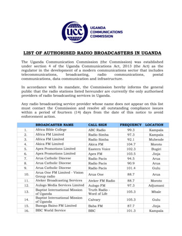
Security in a Radio Controlled Remote SwitchCommunication and ProtocolN NNNNN NNNNN NNNNN NNNNN NNNNN G O CC UUwhere the NNN.NNN N bits represent the 26 bits of the remote’s TxCode code. So we have 32 binarysymbols that we must transmit between the sync and the pauseOne can write a simple program for the Arduino Uno to send a command based on the above description. The listing shows the most important routines. Via the course web you can download thecomplete program.// // Protocol layer,// Manchester like code, each symbol is repeated in complement form// Packet: sync code pause,void Tx433::sendCode(unsigned long code, int len) {int i 0;unsigned long mask 1;mask (len-1);sendSync();while (i len) {if (mask & code) {sendOne();sendZero();Serial.print("1");}else {sendZero();sendOne();Serial.print("0");}mask 1;i ;}sendPause();Serial.println();}/* Send the on/off data to the receiving device/*data TxCode group on ChCode/dim dev/*Packets are send RETRANSMIT times in a row*/void Tx433::sendPackets(unsigned int dev, bool on) {unsigned long data;unsigned int group;dev (dev 3) ? dev : 3;group (dev 3) ? 1 : 0;data TxCode;data (data 1) (1 group);data (data 1) (1 on);data (data 4) (DevControl(channelCode, dev));// Encrypt the data// encrypt(&data,key)for (int i 0; i RETRANSMIT; i ) {sendCode(data, 32);}}// Physical layervoid Tx433::sendZero() {digitalWrite(txpin, HIGH);delayMicroseconds(pulse high);digitalWrite(txpin, LOW);delayMicroseconds(pulse zero low);}void Tx433::sendOne() {digitalWrite(txpin, HIGH);delayMicroseconds(pulse high);digitalWrite(txpin, LOW);delayMicroseconds(pulse one low);}void Tx433::sendSync() {digitalWrite(txpin, HIGH);delayMicroseconds(pulse high);digitalWrite(txpin, LOW);delayMicroseconds(pulse sync low);}void Tx433::sendPause() {digitalWrite(txpin, HIGH);delayMicroseconds(pulse high);digitalWrite(txpin, LOW);delayMicroseconds(pulse pause low);}// Note that to increase the reliability and combat disturbances each command is repeated a number(RETRANSMIT) of times. Note also that we set the value of the on/off bit on Pin 13. Pin 13 is usefulas it is connected to a LED on the Arduino board. In the full program that you download you will findsome additional code lines that are useful for debugging and experiments.Figure 3 show the waveforms on a oscilloscope of the five packages that are transmitted (blue) andreceived (yellow)6
Security in a Radio Controlled Remote SwitchBuilding and testing the remote controllerFigure 3: Transmitted (blue) and received(yellow) data packages44.1Building and testing the remote controllerBuildingNow it is time to put the controller together. Take the circuit drawing that you prepared at home whichshows how to connect the TX module on the breadboard and with the first Arduino unit. Put the TXmodule on the breadboard and connect it to the Arduino Uno. Be careful to connect the right pins. Wetake the GND and 5V from the connector of the Arduino board and we use Pin 13 to control the datainput of the transmitter. Take a wire that has a length that matches this best, it is not so critical as wekeep things close.Now connect the Arduino to you lab computer and fire up the IDE and select the right USB deviceso we can download the program and also trace the program as it executes. Install the TX library forthe module and write a simple loop program to create a loop in which the switch is turned on and ofcontinuously. There is some sample code for this that you can modify.Put the switch in an 230V outlet. You do not have to connect anything to it, we just use the LED on theswitch to see if it is turned on or turned of.4.2TestingAssignment 1 Compile and download the code and let it run on your Arduino. Likely nothing happensin your switch! If it does your are lucky, if not we have to learn the switch the TxCode. Read the instructions of the switch how to do this. It is wise to reset the switch memory and remove any previouslyprogrammed code. You may have to modify your controlling program so the learning process can becarried out.Implement a (loop) program that one can use to make a switch learn the code of your transmitter.Be careful that you do not learn the code used by another group’s system!Before calling help: If nothing works check your wiring. You can test your Arduino with asimple test program that switches the led on and off in a slow pace. If this test program doesnot work consult your assistant. He/She can verify both the Arduino and the TX module.7
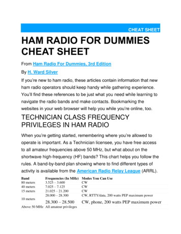
Security in a Radio Controlled Remote SwitchBuilding and testing the receiverAssignment 2 Replace your loop program with the TestLoop loop program in TX.ino and makethis run on your system. Convince yourself that your system works and switch it off to reduce theinterference you might cause to other groups. Call the laboratory assistant and show him/her that yoursystem works with this test loop. When that is done switch your transmitter off again.55.1Building and testing the receiverBuildingHaving the remote working we can assemble the receiver system. Take the circuit drawing that youprepared at home which shows how to connect the RX module on the breadboard and with the secondArduino unit. Put the RX module on a second breadboard and wire the ground and voltage pins. Ifyou do not have a seconf breadboard place the receiver as far as possible from the sender module.Preferably you put an ALU foil of 10cm x 17,3 cm between them and have to foil connected to theground. The receiver is NOT given an antenna, instead we connect the antenna input to the groundvia a 220 Ω resistor, see Figure 4. We do not use the analog output (Pin3) of the RX module; is shouldFigure 4: Coupling of antenna input of the receiver and indicator led.remain unconnected. It is convenient to connect the digital output (Pin2) not only the the Arduino unitbut also to the LED that you serial couple with a 1 KΩ resistor to the ground. This allows to see if thereceiver is receiving signals. Again be careful to connect the right pins. We take the GND and 5Vfrom the connector of the Arduino board.Now connect the Arduino to your lab computer and fire up the IDE and select the right serial connectionso we can download the program and also trace the program as it executes. You should of course nowselect another port. Install the RX library for the module and the program that is the receiving loopwhich prints the received decoded data in the serial monitor log.5.2TestingAssignment 3 Compile and download the code into the receiver Arduino and let it run. Note that youmust set the TxCode in the receiver program to be identical to the one in your Arduino program thatis driving the transmitter. Watch the log screen. It might happen that you see data coming out even ifyour remote is switched off. If that is happening check the program that it is filtering on the TxCode. Ifthat is indeed the case change the receiver TxCode (and do the same in the code for the remote).Question: why is the TxCode set to zero in the RX code?8
Security in a Radio Controlled Remote SwitchA secure NexaShow the working receiver to the assistant for approval.Before calling help: If your receiver is not showing any sign of life check carefully all connections and reload the program and try again. Check that you have the correct voltagefor the receiver. Check the data sheet. If that doesn’t result in any progress consult yourlaboratory assistant.6ReflectionsBy now you should have gotten an insight how the system works. Let us consider its security. Typicallywhat we want is that non-authorized people, simply here those that do nor have my remote, can controlmy switch.Assignment 4 Answer the following questions:1. What is the probability that a command with a randomly chosen TxCode will be accepted by agiven switch (receiver) unit?2. Why is the probability you computed not meaningful from a security point of view?3. Describe a way to attack the system other than just causing radio interference.7A secure NexaObviously, if one wants a more secure solution we have to modify the system. To protect againstnon-authorized person sending false data to a receiving switch one could use an authentication code(MAC) or encryption.Assignment 5 Describe the advantages and disadvantages of an alternative that uses authenticationand of an alternative that uses encryption.If we modify the transmitter we face the problem that irrespectively if we use a MAC or encryptionthat in both cases the original receiver in the switch is not able to understand the security enhancedcommands. Unfortunately we cannot reprogram the receivers in the switches. Hence we have to useinstead our own receiver from now on.Assignment 6 Answer the following questions:1. How many bits for a MAC are needed if you want the probability of impersonating a valid transmitter to be not more than 2 32 ?2. Why is a stream cipher not a good solution for encryption?3. Implement an encryption and decryption routine and integrate it into your solution and verify thatit works.1In the laboratory it is easy to program required keys in the receiver and in the transmitter.9
Security in a Radio Controlled Remote SwitchArduino environmentAssignment 7 Answer the following questions:1. If one uses symmetric key encryption how could one in a real-life system do the key provisioningfrom a transmitter to a receiver?2. If using a asymmetric (public-key) cryptography how you would do then?.Make the necessary modifications to the sending and receiving program to make the command transmission secure. Show the working sender and receiver for your secured setup to the assistant forapproval.8Arduino environmentWe use two Arduino controllers that we program from a lab PC. Both controllers are connected at thesame time to the Lab PC using a USB cable. Hence the PC must have two USB ports. Each IDEenvironment uses a different TTY interface that you must select in the IDE. The PC communicateswith the Arduino via a serial TTY interface running over USB.There is one environment for the controller connected to at TX module and one controller connectedto the RX module. The modules are placed on separate breadboards that are connected to the twoArduino controllers.The Arduino IDE environment should already be installed on your lab PC. So do not do that again. Ifthis laboratory is the first time you work with an Arduino and its development environment it is goodthat you first watch some of the tutorials on Youtube to get a quick introduction, e.g. https://www.youtube.com/watch?v fCxzA9 kg6s or https://www.youtube.com/watch?v kLd JyvKV4Y. Formore guidance on the use the Arduino environment look at [2].We will use the Arduino UNO V3 controller for which the Pin assignments are shown in Figure 7. Wepower the Arduino units via the USB so no external power source is needed. More information on theArduino Uno controller can be found at [3].8.1Tracing outputYou can start window where you can see the output of your Arduino program. Look at Figure 5 how tostart this window. Remark: the Serial.print uses interrupts to write to the serial interface connectedFigure 5: Start of serial monitor.10
Security in a Radio Controlled Remote SwitchREFERENCESto the USB. This means that in the TRX sketch where we use interupts in the receiver and transmitterwe have to be careful in the handling of the interrupts if we also want to write to the serial interface.9Receiver and Transmitter moduleWe use receiver module (RX) and a transmitter module (TX) for AM modulated transmission on433MHZ. The data sheets are available via the course web. Both modules can be operated at 5V.The Pin assignments of both modules are in the data sheets and are given in Fig 6. Hence we usesimple 5v supply source on the Arduino boards to power the TX and RX modules. The RX moduleis insensitive for the voltage that is actually delivered by the Arduino via the USB cable from the PC.The receiver is rather critical and must have an operating voltage of at least 4.9 volt and not more than5.1 volt. Use separate antennas. Sharing a single antenna requires a special construction such as aduplexer https://en.wikipedia.org/wiki/Duplexer.Figure 6: Pin assignments of the transmitter (TX) and receiver (RX) modules.The modules need an antenna. We use here a simple wire of λ/4 of the wavelength λ which is givenby c/f , where c is the speed of light and f is the frequency which is 433Mhz. A shorter antenna willwork too since we will not try to bridge long distances between the receiver and transmitter.Now working with the receiver is tricky in a laboratory environment where other groups are working atthe same time and have their transmitters on. There will be a lot of interference that causes problems.So be warned.When wiring the modules note the correct pin assignments when connecting the supply and GND pinsand that VCC is 5V.10What to do what it doesn’t workIn the first place check the wiring. If you suspect that a module is not working use the instructionsyou find on the course web, http://www.eit.lth.se/index.php?ciuid 936&coursepage 5641#projekt. Follow the steps and check with your laboratory assistant how to proceed.References[1] By Joakim Wesslen: [2] https://www.arduino.cc/en/Guide/HomePage[3] https://www.arduino.cc/en/Main/ArduinoBoardUno11
Security in a Radio Controlled Remote Switch11A receiver and transmitter using one ArduinoA receiver and transmitter using one ArduinoIf you are interested you can also play around with a setup where we use only one Arduino to transmitand receiver control signals, a socalled transceiver. This is found as the RTX sketch solution. It usespin13 to transmit and PIN 8 to receiver in the same manner as before when we had one Arduino forthe receiver and one for the transmitter. The design here is much more trickier and maybe hard tounderstand as it uses interrupts on timers and inputs. Using such a solution we can make a simplerepeater (range extender). The sketch has been verified to work on a Telldus Net with a Proove switch.12
Security in a Radio Controlled Remote SwitchA receiver and transmitter using one ArduinoFigure 7: Pin assignments Arduino Uno V3.13
Security in a Radio Controlled Remote Switch12Approval sheetApproval sheetOn this sheet you assistant will sign-off that did the necessary preparations prior to start the projectin the laboratory rooms. You are NOT allowed to switch the equipment on before he/she has checkedthis and gives an OK to proceed.The assistant also checks and records on this sheet if you got your implementations properly working.SCAN this page and include the scan of your group’s approval sheet in your report.Date:Your name 1:Your name 2:ItemCircuit drawing of TX and coupling to Arduino 1Circuit drawing of RX and coupling to Arduino 2TX circuit working against switchRX circuit working against TXTX and RX circuits working with protected transmission14Approved.
Take the circuit drawing that you prepared at home which shows how to connect the TX module on the breadboard and with the first Arduino unit. Put the TX module on the breadboard and connect it to the Arduino Uno. Be careful to connect the right pins. We take the GND and 5V from the connector of the Arduino board and we use Pin 13 to control .