Transcription
RADIO FREQUENCY SYSTEMSInstallation guide forCELLFLEX Lite cablesHints and recommendationsT h eC l e a rC h o i c e www.rfsworld.com
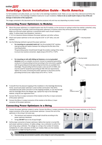
CELLFLEX Lite RADIO FREQUENCY SYSTEMSGeneral hints & recommendations for theinstallation of RFS CELLFLEX Lite cablesCELLFLEX Lite, the new generation of Coaxial cables, provides a number of advantages.The Aluminium outer conductor facilitates an easy transportation (because of the lightweight) and handling. Moreover this cable is easier to bend than the familiar coaxial cableswith a copper outer conductor.However, this new cable generation should be handled and installed according tothe same rules, instructions and regulations as other coaxial cables.These short instructions were written for qualified and experienced personnel. Theydescribe in short words the main points which have to be noted during the installation,without any claim of completeness. It shall highlight the few differences, which have to benoted during the installation of a cable with aluminium outer conductor instead of copper.Always take the standard installation instruction, which is included with each connector orgrounding kit package in addition.Any liability or warranty for results of improper or unsafe use is disclaimed!General remarks:In principle, care must be taken to avoid all such strain that may cause remainingdeformation on the cable, e.g. going below admissible bending radii, kinking, applying toohigh tensile stress or forcible deformation of the corrugated outer conductor (e.g. pullingover sharp edges, over tightening of clamps etc.).Aluminium is slightly softer than copper, accordingly handle with care!Mechanical features of LCF78-50JL & LCF78-50JFNL: Weight, approximately0.36 kg/m(0.24 lb/ft) Minimum Bending radius, single bending120 mm(5in) Minimum Bending radius, repeated bending250 mm(10in) Bending moment13 Nm(9.6lb-ft) Flat crush resistance10 N/mm(57lb/in) Max. tensile force1440 N(324lb) Recommended clamp spacing0.8 m(2ft 7.5in) Max. clamp spacing1.0 m(3 ft 3 in)T h eC l e a r C h o i c e www.rfsworld.comRadio Frequency Systems GmbH / Technical Consulting / Inst. CELLFLEX Lite-20061008 Edition 2006-3Table 1Page 2 of 11
CELLFLEX Lite RADIO FREQUENCY SYSTEMSTransport/shipment & handling of the drumDrums have to be handled carefully, in order to avoid any deformation of the drum and thecable itself. If the drum will be shipped e.g. by van or truck the drum has to be secured againstrolling. "Take special care when loading and unloading". Do not roll the drum fromhigh levels (load floor) of the vehicle without protective measures, e.g. roll the drumfrom the vehicle by using planks as a ramp. Do not drop down the drum!If forklifts are used, the forks must be long enough to engage both flanges of thedrum at a time to avoid cable damage.If a crane is used a special hanger is necessary to ensure vertical application offorces and thus avoiding damage of the drum flanges and the cable.Do not lay the drum on its side, reels must be transported and handled in their upright position only (the cable would be deformed because of its own weight).Make sure that the cable end is always properly sealed and fixed as close aspossible to the drum core.Note the recommended turning direction of the drum, which is shown by an arrowon the drum flange (during installation / pulling of the cable the drum will be on drumstands and will then be turned in the opposite direction to unwind the cable).If the drum is completely protected by wooden planks, these should not be removedbefore the drum is placed (transported) to the final position.Label fixed to the drum. Please follow the instructions.Hoisting/Pulling - Handling of the cable To hoist the cable hoisting grips have to be used, please note the maximumhoisting length of the different hoisting grips available. If necessary multiple hoistinggrips have to be used.Introduce the cable into the hoisting grip, protect the cable against shackles and tiethe upper cable end with connector to the hoisting line, whereby the connectorshould be protected by wrapping e.g. cloth around it.If it can’t be avoided to drag the cable over sharp edges, protective measures mustbe taken, if necessary by positioning an additional rigger at those critical places.In order to protect the cable against any damage protective measures also must betaken if cables have to be pulled in horizontal runs. For example by using piperollers, wooden planks or similar.T h eC l e a r C h o i c e www.rfsworld.comRadio Frequency Systems GmbH / Technical Consulting / Inst. CELLFLEX Lite-20061008 Edition 2006-3Page 3 of 11
CELLFLEX Lite RADIO FREQUENCY SYSTEMSThe minimum bending radius given in table 1 should be strictly observed.The CELLFLEX cable is bend manually with a force that is applied in a distributedmanner (while pressing carefully the hand slides a long the cable [see sketch 2].–make sure to avoid punctual load)Sketch 2Pull carefullybit by bit,while pressing slide your handThe CELLFLEX Lite cable with aluminium outer conductor is easier to bend,but must be handled a little more carefully. Especially during bending,because the required effort (energy) for bending the cable is lower than forcopper cables. Do not twist the cable, e.g. if changing from vertical to horizontal run[see sketch 3].Sketch 3As shown from side (upper) and top (lower)view, do not swing the cable horizontallycreating a twist in the vertical run As shown from side view, rather form alarge bow and pull and guide the cablehorizontally without creating any twistDo not leave the cable hanging in a long free space, e.g. during the installationunder a platform. In adverse conditions additional protective measures may have tobe taken [for example see picture 4].T h eC l e a r C h o i c e www.rfsworld.comRadio Frequency Systems GmbH / Technical Consulting / Inst. CELLFLEX Lite-20061008 Edition 2006-3Page 4 of 11
CELLFLEX Lite RADIO FREQUENCY SYSTEMSProtective measures:temporary fixation ofthe cablePicture 4 Keep the cable end down during cutting and connector installation in order toprevent any particles from entering the cable.Fixation of the cableThe crush resistance of aluminium is lower than copper, this should be considered forinstance if tightening the clamps (especially if these clamps have not been approvedby RFS).For the fixation a number of different clamps can be used, we recommend using the RSBClip. The RSB-Clip is suitable for all fixing situations while at the same time it is the safest(most failure proof) clamp with a large number of exceptional advantages. US standardclamp is the SNAP-xxx or SNAP-ST-xxx.Fixation with RSB-ClipIn any case the recommended and maximum clamp spacing shown in table 1 must alwaysbe considered. The small spacing applies to severe site conditions (wind load, icing etc.),whereas the greater / recommended spacing can be used for less exposed cable runs(e.g. indoor applications).If other clamps are used, the maximum torque has to be noted (lower torque than forcopper cables). The max. torque is shown in table 5.T h eC l e a r C h o i c e www.rfsworld.comRadio Frequency Systems GmbH / Technical Consulting / Inst. CELLFLEX Lite-20061008 Edition 2006-3Page 5 of 11
CELLFLEX Lite RADIO FREQUENCY SYSTEMSTable 5Clamp typeModel Number(e.g.)Information – maximum torqueCan be used without any reservation, torque limit notapplicable because cable holding and clamp fixing aredisconnectedRSB-ClipRSB-78Snap in HangerSNAP-ST-78Can be used without any reservation, torque limit notapplicable because of snap-in fixationBolt-on HangerCLAMP-78Tighten carefully, clamp mustn’t be fully closedSCS clampSCS clampmodifiedMBH (Multi BlockSCS-78-L3M0.5 NmSCS-78-L3M2 – 3 NmMBH-78-62 Nm; clamp mustn’t be fully closedMBH-78-64 - 5 Nm; clamp fully closedHanger)MBH (Multi BlockHanger) modifiedInstallation of connectorBecause of electrochemical potential differences between copper and aluminium theconnectors for the aluminium cables are made with special plating.Connector for CELLFLEX Lite with specialplating, sealed with a rubber sleevePlease note: The first generation of RAPID FIT Lite connectorsare exclusively for use with cables with aluminium outerconductor – a label is attached to the bag for positiveidentification. The second generation will work with both cablesalike, hence no label.Do not use standard RAPID FIT connectors, which are made forcopper cables, for Lite cables.In order to prevent any particles from entering, the cable should be kept downwards duringthe whole installation process of the connector.Connectors can only be installed in straight cable runs. It is not possible to straighten thefront part of the cable; therefore the cable has to be cut 20 cm (7 ”) after straightening thefirst 1m (39”). To reduce scrap, it can help to generally straighten cables before cutting.T h eC l e a r C h o i c e www.rfsworld.comRadio Frequency Systems GmbH / Technical Consulting / Inst. CELLFLEX Lite-20061008 Edition 2006-3Page 6 of 11
CELLFLEX Lite RADIO FREQUENCY SYSTEMSFor the preparation of the CELLFLEX Lite cable a new Preparation tool is available –Model Name: TRIM-78-LF (note: the Preparation tool for the copper cable can not beused!). It is recommended to clean the knife of the tool with spirits from time to time.High precision combinationpreparation tool:TRIM-78-LFFor the dismantling of the jacket (first step) we strongly recommend to use the strippingtool Model Name: JSTRIP-78-2.Stripping tool for thedismantling of jacket:JSTRIP-78-2Put the JSTRIP onto the cable (necessary length / distance seeinstallation instruction of the concerning connector), whereby thestraightened cable end should be kept downwards in order toprevent any particles from entering. Insert a screwdriver into the twosupport holes and start turning, keep a straight line – do not push inany directions and do not twist / leave the right angle line. Continuewith turning by hand (the screwdriver is needed for the start only)until the jacket is cut around, still keep the straight line.Put the tool onto the cable again, whereby the knife should be in the alreadydismantled area. Start again, while turning push the tool slowly to the cable end.The jacket will be cut in a spiral. Turn further by pushing the tool slowly to thecable end. Then remove tool with jacket. Now follow the installation instructionof the connector.T h eC l e a r C h o i c e www.rfsworld.comRadio Frequency Systems GmbH / Technical Consulting / Inst. CELLFLEX Lite-20061008 Edition 2006-3Page 7 of 11
CELLFLEX Lite RADIO FREQUENCY SYSTEMSPlease read the installation instruction that come with the connector very carefully. Takespecial care to remove any metal particles - the silver aluminium particles are not easilyvisible in the dielectric area.Please ensure to properly tighten the connector to the torque specified in the installationinstruction.Installation of the Grounding KitIn order to avoid any corrosion problems, the body of the Pre-Formed Grounding Kit modelname GKFORM20-78LITE is made of aluminium as the outer conductor of the cable.Pre-Formed Grounding Kitfor LCF78-50Lite cable:GKFORM20-78LiteBecause of electrochemical potential differences between copper and aluminium donot use the groundings, which are made for copper cables and visa versa!New versions will be made available with compatible plating of the contact elements toensure functionality with aluminium and copper conductors.Please follow the included installation instruction carefully.For the dismantling of the jacket we also strongly recommend to use the Stripping toolwith the model name: JSTRIP-78-2.Stripping tool for thedismantling of jacket:JSTRIP-78-2T h eC l e a r C h o i c e www.rfsworld.comRadio Frequency Systems GmbH / Technical Consulting / Inst. CELLFLEX Lite-20061008 Edition 2006-3Page 8 of 11
CELLFLEX Lite RADIO FREQUENCY SYSTEMS70mm2 “45 – 50mm1 “ – 2“Put the JSTRIP onto a straight running part of cable. Insert a screwdriver into the twosupport holes and start with turning, keep a straight line – do not push in any directionsand do not twist / leave the right angle line. Continue with turning by hand (the screwdriveris needed for the start only) until the jacket is cut around, still keep the straight line. Makea mark onto the cable jacket in a distance of 70 mm (2 ”) from the beginning of the firstcut (that’s 50 mm (2”) which is needed for the grounding kit installation and the part of thetool from the end of the knife to the end of the tool). Put the tool onto the cable again,whereby the knife should be in the already dismantled area. Start again, while pushing thetool slowly in direction of the marking. The jacket will be cut in a spiral. Turn further bypushing the tool very slowly until reaching the marking.If the tool is on the mark, turn further, but now push a little bit in the direction backwards inorder to finish the cut in straight line / in a right angle.Note: If the tool has been started to cut in a spiral, the tool will move continuously by itselfin the direction of beginning. If the mark area is reached, this movement has to bestopped by pushing carefully in the opposite direction. Because of this problem werecommend to make a practice strip on a part of cable which is not needed for theinstallation. If this process is not easy enough / not acceptable a clamp (e.g. RSB-Clip)can be placed on the mark place. This clamp will then stop the movement of the tool inthe final position [see pictures 6].Pictures 6T h eC l e a r C h o i c e www.rfsworld.comRadio Frequency Systems GmbH / Technical Consulting / Inst. CELLFLEX Lite-20061008 Edition 2006-3Page 9 of 11
CELLFLEX Lite RADIO FREQUENCY SYSTEMSPlease put the body of the grounding kit very carefully around the cable, in order toprevent damaging the outer conductor. Then tighten the nuts carefully because these aremade of aluminium as well.Finally use the supplied sealing materials as described in the instruct
over sharp edges, over tightening of clamps etc.). Aluminium is slightly softer than copper, accordingly handle with care! General hints & recommendations for the installation of RFS CELLFLEX Lite cables Mechanical features of LCF78-50JL & LCF78-50JFNL: Weight, approximately 0.36 kg/m (0.24 lb/ft) Minimum Bending radius, single bending 120 mm (5in) Minimum Bending radius .


