Transcription
I MANUALE DELL’UTENTE GB USER MANUAL D ANWENDERHANDBUCHF M A N U E L D E L’ U S A G E R E M A N U A L D E L U S U A R I OA.D.: Holbein & Partners - COD. 03662035 - Edition: April 2009ELEKTRA SRLVIA A. VOLTA,18 - 31030 DOSSON DI CASIER (TREVISO) ITALYTEL. ( 39) 0422 490405 R.A. - FAX ( 39) 0422 490620E-mail: info@elektrasrl.com - Website: www.elektrasrl.comIGBDFEMANUALE DELL’UTENTEUSER MANUALANWENDERHANDBUCHMANUEL DE L’USAGERMANUAL DEL USUARIOI T A L I A NE S P R E S S OC O F F E EM A C H I N E SIMacchine da caffè espresso professionaliGBProfessional espresso coffee machinesDProfessionelle EspressomaschinenFMachines à café expresso professionnellesEMáquinas Profesionales para café espresso
ITALIAN ESPRESSO COFFEE MACHINES3
gb48
gbgb49
gbCONTENTSA INTRODUCTION53B GENERAL RECOMMENDATIONS AND SAFETY REGULATIONS54C DESCRIPTION OF THE APPLIANCE56123456789101112131415161718192021COFFEE DISPENSINGDISPENSING OF HOT WATER AND STEAMELIMINATION OF CALCIUM AND MAGNESIUM SALTS FROM THE WATERELIMINATION OF CALCIUM AND MAGNESIUM SALTS FROM THE WATERAUTOMATIC REGENERATION OF THE WATER SOFTENER RESINSELIMINATION OF CHLORINE AND ORGANIC COMPOUNDS FROM THE WATERCONTROL OF WATER LEVEL IN THE BOILERCONTROL OF WATER TEMPERATURE IN THE BOILERSTABILIZING THE BREWING TEMPERATUREMEASURING THE BREWING PRESSUREMEASURING THE BREWING PRESSUREMEASURING THE WATER SUPPLY PRESSUREPROTECTING THE HEATING ELEMENTSPROTECTING FROM OVERHEATINGUPPER CUP TRAYUPPER CUP HEATER TRAYDRIP TRAYUSER ALERTSUSER ALERTSBASIC PROGRAMMINGSPECIAL (S-M-C-B)(K-Kwts)(K-Kwts-S-M-C-B)(K-Kwts)D UNPACKING60E INSTALLATION123456789101150ADJUSTING THE FEETWATER CONNECTIONSWATER CONNECTIONSWATER SOFTENER CONNECTIONWATER SOFTENER CONNECTIONCONNECTION WITHOUT WATER SOFTENERDRAIN CONNECTIONELECTRICAL CONNECTIONSFILLING THE HYDRAULIC CIRCUITSFILLING THE HYDRAULIC CIRCUITSFLUSHING THE MACHINE (USA NSF wts)(K-Kwts-S-M-C-B)6161616262626363646465
123456789SELECTION OF LANGUAGESETTING OF DATE AND TIMESTORING OF MEASURED WATER SUPPLY HARDNESSSTORING OF WATER SOFTENER TYPEADJUSTING THE BREWING TEMPERATUREADJUSTING THE BREWING PRESSUREADJUSTING THE SALINITY OF THE BREWING WATERPROGRAMMING OF COFFEE DOSESPROGRAMMING OF NIGHT ts-S-M-C-B)G USE1234567891011121314SWITCHING ONUSE OF THE WORKING AREASUSE OF THE WORKING AREASUSE OF THE WORKING AREASCOFFEE DISPENSING WITH MANUAL DOSINGCOFFEE DISPENSING WITH AUTOMATIC DOSINGCOFFEE DISPENSING WITH AUTOMATIC DOSING BUT WITHPOSSIBILITY OF STOPPING IT MANUALLYWARMING THE CUPSWARMING THE CUPSMAKING THE COFFEEMAKING CAPPUCCINO, MILK AND OTHER HOT DRINKSMAKING TEA – CAMOMILE TEA - ETCUSING BASIC PROGRAMMINGUSING BASIC K-Kwts-S-M-C-B)(S-M-C-B)(K-Kwts)7071717171727279H MAINTENANCE AND CLEANING1234567891011DAILY CLEANING OF THE GROUPS AND FILTERHOLDERSDAILY CLEANING OF STEAM WANDSWEEKLY CLEANING OF THE GROUPSWEEKLY CLEANING OF THE FILTERS AND FILTERHOLDERSWEEKLY CLEANING OF LOWER DRIP TRAYWEEKLY CLEANING OF BODYCLEANING THE WATER SOFTENERREGENERATING THE WATER SOFTENER RESINSREGENERATING THE WATER SOFTENER RESINSCHANGING THE ACTIVATED CARBON CARTRIDGERINSING THE WATER TREATMENT )(Kwts)(Kwts)518080808080808081828282gb67F ADJUSTMENTS
83I DATA MANAGEMENTgb12345DISPLAY OF FUNDAMENTAL PARAMETERSDISPLAY OF FUNDAMENTAL PARAMETERSDISPLAY OF FUNDAMENTAL PARAMETERSDISPLAY AND RESET OF COFFEE PRODUCTIONDISPLAY AND RESET OF WATER CONSUMPTION(S-M-C-B)(K)(Kwts)(K-Kwts)(K-Kwts)J TROUBLESHOOTING123456789101112131415161718WARNING: BUFFER BATTERY ABOUT TO GO FLATSTEAM DOES NOT COME OUT OF THE WAND WHEN THEMACHINE IS HOTWARNING: WATER LEVEL CONTROL SYSTEM FAULTWATER COMES OUT OF THE STEAM WANDFLASHING OF THE PUSHBUTTON LED DURING DISPENSINGWARNING OF NOT SATISFACTORY BREWING AND FLASHINGOF THE DISPENSING PUSHBUTTON LEDWATER DOES NOT COME OUT OF THE DISPENSING GROUPWHEN THE MANUAL BUTTON IS USEDONE DISPENSING GROUP STARTS UP ON ITS OWNWARNING: INADEQUATE WATER SUPPLY PRESSUREWARNING: NO WATER IN THE BOILERWARNING: BREWING TEMPERATURE CONTROL FAULTONE DISPENSING GROUP DOES NOT HEAT SUFFICIENTLYTHE GAUGE SHOWS A BOILER PRESSURE NOTBETWEEN 0.6 AND 1.6 BARTHE GAUGE SHOWS A BREWING PRESSURE NOTBETWEEN 8 AND 9 BARWARNING: WATER SOFTENING SYSTEM FAULTNO SALT LOADINGTHE WATER SOFTENER AND ACTIVATED CARBON CARTRIDGE CAPSDO NOT OPENTHE DRIP TRAY IS FULL AND OVERFLOWING WITH 9K DISPOSAL OF THE APPLIANCEL1290TYPE APPROVALSEUROPEAN TYPE APPROVALSAMERICAN TYPE APPROVALS838383838391(K-Kwts-S-M-C-B)(S-M)9191M TEST DOCUMENTATION218N GUARANTEE21952
This manual applies to the entire range of professional coffee machines manufacturedby ELEKTRA.Each topic has been specifically treated in a separate paragraph for each model belongingto the range, indicating the title of the paragraph itself and the models to which it refers,using the letters shown below:-K Kwts S M C B K modelKwts modelSIXTIES modelMODERN and GOLD modelsCLASSIC modelBELLE EPOQUE model(Compact)(Maxi and Extramaxi)(Barlume)(Vertical 2-3 units)The SIXTIES model Deliziosa is not included; see the user’s manual October 2007 editionfor this model.The manual contains all the instructions required for the installer,the operator (barman) and the manager or owner of the bar.It also contains some useful recommendations for guiding the service technicianin the event of malfunctioning.U.S.A. - ATTENTION:These instructions include some particular specifications for the US and Canadianmarkets.53gbA INTRODUCTION
B GENERAL RECOMMENDATIONS ANDSAFETY REGULATIONSgb123454This booklet is an essential and integral part of the product and must be given to the user.It contains basic safety instructions that must be followed for the installation, operation andmaintenance of the appliance.Save these instructions.After having unpacked the appliance, make sure it is intact.If in doubt, do not use the appliance and contact a qualified engineer.The packing elements (plastic bags, polystyrene foam, nails, etc.) should not be left withinreach of children since they are potential sources of danger.Before connecting the appliance, check that the mains electricity supply corresponds to thedata given on the rating plate.The rating plate is located under the drip tray (K-Kwts-S-M-C) or inside the upper cup tray (B).The appliance should be installed by a qualified engineer according to the manufacturer’sinstructions and in compliance with current safety regulations.Incorrect installation could cause injury to persons or animals and damage to property, forwhich the manufacturer cannot be held liable.This appliance is only electrically safe when it has been connected to an efficientgrounding system in compliance with current safety regulations.Make sure that this fundamental safety requirement has been observed and if in doubtrequest a thorough check of the system by a qualified electrician.The manufacturer cannot be held liable for any damage that may be caused by failure toground the appliance.Check that the current carrying capacity of the system is adequate for the maximum ratedoutput of the appliance (as indicated on the rating plate).If in doubt, apply to a qualified technician. He should also make sure that the section of thecables is adequate for the power absorbed by the appliance.Do not use adapters, multiple current taps or extension cables.If it is absolutely necessary, only use plugs, simple or multiple adapters and extensions thatcomply with current safety regulations. Make sure, however, that the limit of current carryingcapacity does not exceed that indicated on the simple adapter and extensions or the maximum power value indicated on the multiple adapter.This appliance should only be used for the purpose for which it was designed.Any other use is to be considered as unsuitable and therefore dangerous.The manufacturer cannot be held liable for any damage or injury caused by improper, wrongor unreasonable use.
678910111255gb5When using electrical appliances, basic safety precautions should always be followed:- the appliance should be used in environments where the temperature does not fall below5 C or rise above 40 C;- the appliance has a water circuit containing water, which must not be allowed to freezeotherwise the appliance could be damaged;- the appliance should not be cleaned using water jets or installed in a place where waterjets could be used for cleaning;- the appliance should be installed on the level – it must not slope;- do not touch the appliance when hands or feet are wet or damp;- do not operate the appliance barefoot;- do not use extension cables in bathrooms or shower-rooms;- do not tug the power supply cable to disconnect the appliance from the mains supply;- do not expose the appliance to the elements (rain, sun, etc.);- do not allow children or incompetent persons to use the appliance.Disconnect the appliance from the mains electricity supply before carrying out anymaintenance, by pulling out the plug or by switching off at the mains switch.To clean the appliance, follow the instructions in this booklet.In the event of failure or malfunctioning of the appliance, switch it off and under nocircumstances try to repair it yourself.Always request service by a qualified technician.Any repair, electrical or mechanical adjustment should only be carried out at the factoryor by an authorized service center using only original spare parts.Failure to comply with these instructions could jeopardize the safety of the appliance.The appliance should be connected to the electricity supply through a multipolar linkedswitch having a contact separation of at least 3 mm in all poles, in compliance with currentsafety regulations.Unwind the whole power supply cable to prevent dangerous overheating.Do not obstruct the intake and outlet grilles. In particular do not cover the upper cup traywith a cloth or such like.The supply cable of this appliance should not be replaced by the user.Should the cable be damaged, switch off the appliance and apply solely to a qualifiedelectrician for replacement.Should the machine be used no longer, it must be made inoperative by cutting the supplycable after having disconnected it from the electrical power supply.Make sure that all those parts which could be possible sources of danger are made harmless.
C DESCRIPTION OF THE APPLIANCEThe main functions of the machine, and its relative parts, are described below, with a viewto ensuring its maximum performance.gb1 COFFEE DISPENSING (K-Kwts-S-M-C-B)Independent dispensing groups with predosed or manual selections.Filterholders for one or two cups.2 DISPENSING OF HOT WATER AND STEAM (K-Kwts-S-M-C-B)The machine has one or two steam wands and a hot water dispenser which allows the useof large milk or water containers thus guaranteeing good general ergonomics.3 ELIMINATION OF CALCIUM AND MAGNESIUM SALTS FROM THE WATER(K-S-M-C-B)This enables the elimination of scale deposits in the machine thanks to a water softenerthat softens the water, eliminating the calcium and magnesium salts contained in it.The water softener is not incorporated in the machine and has an independent manualor automatic function.4 ELIMINATION OF CALCIUM AND MAGNESIUM SALTS FROM THE WATER(Kwts)This enables scale deposits to be removed from the machine.It consists of an ion exchange resin water softener, completely and automatically managedby the machine.5 AUTOMATIC REGENERATION OF THE WATER SOFTENER RESINS (Kwts)When the resins in the water softener are used up, all the operator has to do, on receivingthe automatic prompt from the machine, is to load the salt.During regeneration, the system automatically excludes the water treatment circuit fromthe machine water supply, allowing the machine to operate without it.6 ELIMINATION OF CHLORINE AND ORGANIC COMPOUNDS FROM THEWATER (Kwts)Removes the bad taste and deposits caused by the Chlorine and eliminates bacteria, makingthe water purer.It consists of a silver-loaded activated carbon cartridge fitted inside the machine,at the water supply inlet.The system signals the exhaustion of the cartridge in relation to the volume of water thatit has treated and excludes it automatically from the machine water supply circuit, allowingthe machine to continue operating without it.7 CONTROL OF WATER LEVEL IN THE BOILER (K-Kwts-S-M-C-B)This is done by means of a level probe which controls the water level in the boiler,topping it up automatically when required.56
8 CONTROL OF WATER TEMPERATURE IN THE BOILER (K-Kwts-S-M-C-B)gbThis keeps the temperature of the coffees constant as opposed to the temperatureand the pressure of the steam.Consequently, it also controls the pressure in the boiler.9 STABILIZING THE BREWING TEMPERATURE (K-Kwts-S-M-C-B)Each dispensing group has a heating circuit for brewing water that functions witha heat exchanger.This circuit ensures that the dispensing group remains at a constant and optimal temperatureeven when it is not being used thanks to the effect of the natural circulation of hot waterflowing through the circuit itself.10 MEASURING THE BREWING PRESSURE (K-S-M-C-B)This enables the manual regulation of pump pressure during coffee dispensing.The pressure is displayed on the gauge clearly visible in the working area.On the K model, the gauge is fitted inside the machine.11 MEASURING THE BREWING PRESSURE (Kwts)Through the reading of the display, this enables the manual regulation of pump pressureduring coffee dispensing.12 MEASURING THE WATER SUPPLY PRESSURE (Kwts)Enables automatic protection in the event of a water supply stoppage.13 PROTECTION OF THE HEATING ELEMENTS (K-Kwts-S-M-C-B)This consists of a safety level probe that triggers the cutting off of power tothe heating elements.Resetting takes place through Basic Programming.See chapter “G – USE”.14 PROTECTION FROM OVERHEATING (K-Kwts-S-M-C-B)In each of following cases:- Excessive duration of heating- Exceeding of maximum allowable temperature value, the heating elements are disabledand a major fault is reported.15 UPPER CUP TRAY (S-M-C-B)These models are equipped with cup heater trays with the capacity to contain a largenumber of cups on various levels and to keep them warm in order to guarantee an excellentcup of coffee.The heat is generated by a natural flow of hot air from the inside of the machine.57
gb16 UPPER CUP HEATER TRAY (K-Kwts)Models equipped with larger cup heater trays and electric heating with automatictemperature control.The heating can either be enabled or disabled.17 DRIP TRAY (K-Kwts)Improves the draining and cleaning of the work counter.Avoids blocking of the drain.18 USER ALERTS (S-M-C-B)The machine can give the user a series of alerts through different LED light on/off combinationsfor each coffee dispensing button, on each of the two or three groups on the machine.Symbols are used in this manual to indicate these alerts as follows:Group 1Group 2Group 3Led all off:Led of the long single coffee button of group 1 on with fixed light:Led of the long single coffee button of group 1 flashing:Led of the long single coffee button of group 1 slowly fading light:Slow flashing led sequence:Fast flashing led sequence:19 USER ALERTS (K-Kwts)The machine can give the user a series of alerts written in the selected language throughan alphanumeric display arranged along two rows with sixteen characters each.The writing may be fixed, scrolling or fixed but divided over two or more screen displaysif very long: wait and read the complete written message to ensure you fully understandthe alert.58
This enables the implementation of some of the Adjustment, Maintenance and DataManagement functions.It also facilitates the providing of telephonic assistance.Basic Programming is the exclusive responsibility of the installer/service technicianor of the owner of the business.It is carried out using the key provided.These functions are as follows:-Selection of the languageSetting of date and timeSetting of increase (or decrease) of brewing temperatureStorage of measured water hardnessSelection of softener typeProgramming of coffee dosesProgramming of night cycleReset of heating element safety deviceRinsing of the water treatment circuitReset of scheduled maintenance callReset of activated carbon cartridge changing alertDisplay and reset of coffee productionDisplay and reset of water ts-S-M-C-B)(Kwts)(K-Kwts)(Kwts)(K-Kwts)(K-Kwts)21 SPECIAL PROGRAMMING (K-Kwts)This allows the personalization of certain machine functions according to important servicing,marketing or individual end Customer requirementsSpecial Programming is the exclusive responsibility of the dealer’s specialized technicianwho will have been specifically trained by ELEKTRA to do so.Special Programming should be carried out on the dealer’s premises prior to installation.It is carried out via PC by connecting a special cable to the machine’s electronic control unitand the ELEKTRA program.These functions are as follows:-Setting of preventive maintenance program.Activation of start of dispensing only upon reaching the ideal brewing temperature.Activation of brewing suitability control according to Italian espresso standards.Activation of a maximum time between one regeneration and another (WTS version only).Personalization of maximum coffee dispensing time.Personalization of the maximum heating element “on” time.Personalization of the reset code for the scheduled maintenance call, coffee productionand water consumption.Saving and printing of all machine configuration data.Saving and printing of all machine cumulative historical data.59gb20 BASIC PROGRAMMING (K-Kwts-S-M-C-B)
D UNPACKINGgbPackaging is carried out with the aim of protecting the machine from damage duringtransportation.The packaging materials used are recyclable. They are, therefore, chosen accordingto environmental protection criteria and ease of disposal, the latter process being gearedat further integration in productive cycle materials.Thanks to this mechanism, not only is the volume of waste reduced but a more rationaluse of non renewable resources is also ensured.1) Cut the strap that keeps the box closed.2) Open the top of the box and remove the shock-proof panels inside, remove the accessories contained inside them and take out the present manual, keeping these articlesto hand for the later phases of use of the appliance.Remove the nylon bag covering the upper part of the machine and put it in a safe3)place out of the reach of children.4) Working with at least one other person, grasp the base of the machine from insidethe box and remove it by lifting it upwards.5) Remove any other packaging materials and protections attached to the machine.6)Hand the packaging materials over to an authorized enterprise for disposal andrecycling.60
Installation must be carried out exclusively by a specialized technician from the TechnicalAssistance Service.The company Elektra declines any and all responsibility for tampering or interventionscarried out by non authorized persons.Such intervention automatically renders the guarantee null and void.ATTENTION: (USA NSF requirements)The equipment is to be installed to comply with the Basic Plumbing Code of theBuilding Officials and Code Administration International, Inc. (BOCA) and the FoodService Sanitation Manual of the Food and Drug Administration (FDA).1 ADJUSTING THE FEET (K-Kwts)Place the machine on the work counter and ensure that it is level, by adjusting the lengthof the feet.Turn the chrome-plated foot counter-clockwise, when viewed from underneath, to lengthenit and clockwise to shorten it. There are no screws or nuts to be loosened or tightened.2 WATER CONNECTIONS (K-S-M-C-B)The water is fed thanks to a connection with the drinkable water supply at a minimumpressure of 1.5 bar and a maximum pressure of 4 bar.Should the water supply pressure exceed 4 bar, install a pressure reducer upline of thecoffee machine / water softener system.An external check-valve may be required to meet local regulations.The machine has a flexible steel-braided connection pipe with a 3/8 female connection,approx. 1.5 metres in length.1) Connect the flexible pipe to the coupling located on the bottom of the machine.2) If the machine is being installed without a water softener (not recommended unlessa centralized water softening system has been installed) connect the flexible pipeto the water supply.3 WATER CONNECTIONS (Kwts)The water is fed thanks to a connection with the drinkable water supply at a minimumpressure of 1.5 bar and a maximum pressure of 4 bar.Should the mains pressure exceed 4 bar, install a pressure reducer upline of the coffeemachine/water softener system.An external check-valve may be required to meet local regulations.The machine has three flexible connecting pipes with 3/8 female connections,approx. 1.5 metres in length.1) Connect each flexible pipe to the couplings located on the bottom of the machine.The three couplings are marked “1”, “2” and “W”.2) Flush the water supply to ensure that it is clean and after couple to it the flexible pipecoming from the “W” coupling.Do not open the water supply.61gbE INSTALLATION
4 WATER SOFTENER CONNECTION (K-S-M-C-B)gbIf the standard water softener with completely manual valves is to be used,follow the instructions below.If semiautomatic or automatic water softeners are to be used, follow the specific instructionsprovided in the handbooks accompanying the water softeners themselves.The water softener has a flexible steel-braided connecting pipe with 3/8 female connections,approx. 0.7 metres in length, and a semitransparent pipe approx. 0.7 metres in length.1) Flush the water supply to ensure that it is clean.Couple the 0.7 metre long flexible pipe to the water softener inlet (upper valve) and thewater supply.2) Ensure that the valve levers are in the vertical position.3) Allow at least 10 litres of water to flow through the water softener by turning on the watersupply, turning the upper valve lever counter-clockwise and the lower valve lever slightlycounter-clockwise.4) Only reclose the lower valve, by turning it to the vertical position, when the wateris clear and colourless.5) Connect the 1.5 metre long flexible pipe, previously hooked up to the machine,to the lower valve of the water softener.6) Cut the semitransparent pipe into two pieces, one 0.4 metres long and the other 1.3metres long.7) Connect the shorter piece to the pipe-end fitting of the upper valve.8) Connect the longer piece, rolled up, to the pipe-end fitting of the lower valve, after ensuringthat the gigleur is well-tightened to the fitting itself.9) Turn the lower valve lever counter-clockwise so as to feed the machine.5 WATER SOFTENER CONNECTION (Kwts)The machine must only be used with the three types of special water softener suppliedby ELEKTRA, i.e.:8 litre ELEKTRA water softener- 12 litre ELEKTRA water softener- 16 litre ELEKTRA water softenerNo other type or brand of water softener may be used with this model.1) Connect the flexible pipe connected to coupling “1” on the machine to the correspondingcoupling “1” on the water softener.2) Connect the flexible pipe connected to coupling “2” on the machine to the correspondingcoupling “2” on the water softener.Do not open the water supply.6 CONNECTION WITHOUT WATER SOFTENER (Kwts)Although not recommended, the machine can be used without water softener if necessary.Contact Technical Assistance.62
The machine has a rubber connecting pipe with pipe-end fitting, approx. 1.5 metres in length.This pipe must be made to flow into a fixed drain manifold with a minimum internal diameterof 35 mm located underneath the machine work counter.The space created by difference in diameter of the two pipes inserted one into the othermust be left free for the venting of air during the discharging of the water.1) Hook up the rubber pipe from the metal pipe or from the plastic drain box installedin the machine to the drain manifold located underneath the counter, ensuring thatit does not sag and that it is not strangled.8 ELECTRICAL CONNECTIONS (K-Kwts-S-M-C-B)The machine is equipped with a connecting power cable, approx. 2 metres in length,with 5 wires of the following colours:- Green/Yellow:- Blue:- Brown:- Black:- Grey:GroundNeutralPhase 1Phase 2Phase 3The wires should, preferably, be connected to a terminal board on the electric switchboard; if a plug is to be used, it should be an industrial plug with a sufficient capacity to powerthe machine.The connection may be made without any modification being required to the machine,either to a single-phase 230VAC power supply or to a triple phase 400VAC N3 power supply,as follows:8.1 SINGLE-PHASE 230VAC CONNECTIONHook up the Ground and Neutral wires to the two respective terminals on the electric switchboard.Join up the three wires of phases 1, 2 and 3 themshelves and connect them to the singleterminal of the phase present in the electric switchboard.8.2 THREE-PHASE 400VAC N3 CONNECTIONHook up the Ground and Neutral wires to the two respective terminals on the electric switchboard.Connect each of the three wires of phases 1, 2 and 3 to the respective terminalsof the phases present in the electric switchboard.The wiring diagram and electrical data are shown on the two plates located underneaththe drip tray (K-Kwts-S-M-C) or inside the upper cup tray (B).63gb7 DRAIN CONNECTION (K-Kwts-S-M-C-B)
gb9 FILLING THE HYDRAULIC CIRCUITS (K-S-M-C-B)1) Ensure that the water supply is turned on.2) Switch on the machine by turning the main switch from position “0” to “1”:the machine goes on and loads water into the boiler, while powering the heating elements.10 FILLING THE HYDRAULIC CIRCUITS (Kwts)Before switching on the machine, fill the water treatment hydraulic circuit.Proceed as follows:1) Open the water softener cap.2) Open the activated carbon cap and take the cartridge out.3) Top up with water the cartridge container until the water softener has filled up completelyand starts overflowing.4) Close the water softener cap.5) Put the activated carbon cartridge in, top up with water to the brim and reclose.6) Turn on the water supply.Now the machine is ready to be switched on and adjusted.If there are problems in opening the two caps, consult chapter “J – TROUBLESHOOTING”.64
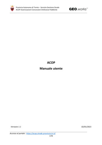
ATTENTIONThe technician in charge of installing the appliance should carry out the followingoperations before going to install the equipment at the customer’s.ATTENTION:The unit should be flushed through prior to putting it into service.With reference to the hydraulic scheme given below, before putting it into service,the machine must be flushed through as follows:A) FLUSHING THE DELIVERY GROUP1) Switch the machine on and make sure that it is up to pressure.2) Let 5 liters of hot water flow from each delivery group N 18 through the filter N 19located on the filter holder N 21.B)1)2)3)4)FLUSHING THE BOILERSwitch the machine on and make sure that it is up to pressure.Switch the machine off.Connect a rubber drainage hose to hot water tap N 14Open hot water tap N 14 until the boiler is completely drained of water(time required: 2 minutes):Note: it is the boiler pressure that makes the water drain off.C)1)2)3)4)5)6)FLUSHING THE HEAT EXCHANGERSRemove the upper cup tray.Remove the pipe N 23 and the injector of heat exchanger N 8.Remove the upper cap of the heat exchanger N 8.Wait until the heat exchanger is completely empty.Re-connect the pipes to heat exchanger.Reassemble the upper cup tray.65gb11 FLUSHING THE MACHINE (USA NSF requirements)
HYDRAULIC SCHEMEgb12345678910111266WATER SUPPLYWATER SOFTENERENTRY WATER CONNECTIONMOTOR / PUMPONE WAY VALVEINLET SOL. VALVEBOILERHEAT EXCHANGERSAFETY VALVEVACUUM BRAKE VALVEFILTEROREFICE1314151617181920212223STEAM VALVEHOT WATER VALVEEXPANSION VALVEGAUGEGROUP SOLENOID VALVECOFFEE DELIVERY GROUPFILTERWATER FLOW METERFILTERHOLDERHOT WATERCOLD WATER
F ADJUSTMENTS1 SELECTION OF LANGUAGE (K-Kwts)gbThis allows the conversion of all the communications made by the machine into Italianor English or French or Spanish or German.This is done through the Basic Programming.See chapter “G – USE”.2 SETTING OF DATE AND TIME (K-Kwts-S-M-C-B)This is used to set the minutes, hours, days, months and year for correct night cyclemanagement and dating of statistical data.This is done through the Basic Programming.See chapter “G – USE”.3 STORING OF MEASURED WATER SUPPLY HARDNESS (Kwts)Together with the storing of the type of water softener, this allows the machine to automaticallycalculate the volume of softened water available before saturation of the softener resins and,consequently, to start the automatic regeneration process.Measure the hardness of the water supply using the ELEKTRA kit provided, expressedin French degrees ( F), and store it through Basic Programming (see chapter “G – USE”).Contact Technical Assistance.4 STORING OF WATER SOFTENER TYPE (Kwts)This allows the machine to automatically calculate the vo
ELEKTRA SRL VIA A. VOLTA,18 - 31030 DOSSON DI CASIER (TREVISO) ITALY TEL. ( 39) 0422 490405 R.A. - FAX ( 39) 0422 490620 E-mail: info@elektrasrl.com - Website: www.elektrasrl.com I MANUALE DELL'UTENTE GB USER MANUAL D ANWENDERHANDBUCH F MANUEL DE L'USAGER E MANUAL DEL USUARIO A.D.: Holbein & Partners - COD. 03662035 - Edition: April 2009 I