Transcription
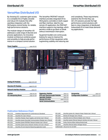
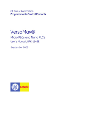
GE Fanuc AutomationProgrammable Control ProductsVersaMax Micro PLCs and Nano PLCsUser’s Manual, GFK-1645ESeptember 2005
GFL-002Warnings, Cautions, and Notesas Used in this PublicationWarningWarning notices are used in this publication to emphasize that hazardous voltages,currents, temperatures, or other conditions that could cause personal injury exist in thisequipment or may be associated with its use.In situations where inattention could cause either personal injury or damage to equipment,a Warning notice is used.CautionCaution notices are used where equipment might be damaged if care is not taken.NoteNotes merely call attention to information that is especially significant to understanding andoperating the equipment.This document is based on information available at the time of its publication. While effortshave been made to be accurate, the information contained herein does not purport to cover alldetails or variations in hardware or software, nor to provide for every possible contingency inconnection with installation, operation, or maintenance. Features may be described hereinwhich are not present in all hardware and software systems. GE Fanuc Automation assumes noobligation of notice to holders of this document with respect to changes subsequently made.GE Fanuc Automation makes no representation or warranty, expressed, implied, or statutorywith respect to, and assumes no responsibility for the accuracy, completeness, sufficiency, orusefulness of the information contained herein. No warranties of merchantability or fitness forpurpose shall apply.The following are trademarks of GE Fanuc Automation, Inc.Alarm MasterGeniusProLoopSeries SixCIMPLICITYHelpmatePROMACROSeries ThreeCIMPLICITY masterPowerTRACVersaPointField ControlMotion MateSeries 90VersaProGEnetPACSystemsProficySeries FiveSeries OneVuMasterWorkmaster Copyright 2005 GE Fanuc Automation North America, Inc.All Rights Reserved
ContentsChapter 1Introduction. 1-1VersaMax Micro PLC and Nano PLC Models. 1-2Comparison of Program and Data Memory Available . 1-5Comparison of PLC Features. 1-6Comparison of I/O and Power Features for PLCs . 1-7Comparison of I/O and Power Features for Expansion Units . 1-8VersaMax Serial to Ethernet Adapter . 1-9Logic-Driven Read/Write Flash Memory Feature. 1-10Chapter 2VersaMax Nano PLCs . 2-1IC200NAL110 Nano PLCs with 10 Discrete Points and 1 Analog Input: (6) 12 VDC In,(4) Relay Out, 1 Analog Input, 12VDC Power Supply . 2-4IC200NAL211 Nano PLC with 10 Discrete Points and 1 Analog Input: (6) 12 VDC In, (4)Relay Out, 1 Analog Input, 24VDC Power Supply . 2-7IC200NDD010 10 Point Nano PLC: (6) 12 VDC In, (4) 12 VDC Out, 12 VDC PowerSupply . 2-10IC200NDD101 10 Point Nano PLC: (6) 24 VDC In, (4) 12 VDC Out, 24 VDC PowerSupply . 2-13IC200NDR001 10 Point Nano PLC: (6) 24 VDC In, (4) Relay Out, 24 VDC Power Supply2-16IC200NDR010 10 Point Nano PLC: (6) 24 VDC In, (4) Relay Out, 12VDC Power Supply2-19Chapter 3VersaMax 14-Point Micro PLCs . 3-1IC200UAA003 14 Point Micro PLC, (8) 120VAC In, (6) 120VAC Out, 120/240VACPower Supply . 3-4IC200UAR014 14 Point Micro PLC, (8) 120VAC In, (6) Relay Out, 120/240VAC PowerSupply . 3-6IC200UDD104 14 Point Micro PLC, (8) 24VDC In, (6) 24VDC Source Out, 24VDCPower Supply . 3-8IC200UDD112 14 Point Micro PLC, (8) 12VDC In, (6) 12VDC Out, 12VDC PowerSupply . 3-11IC200UDR001 14 Point Micro PLC, (8) 24VDC In, (6) Relay Out, 120/240VAC PowerSupply . 3-14IC200UDR002 14 Point Micro PLC, (8) 24VDC In, (6) Relay Out, 24VDC Power Supply3-17IC200UDR003 14 Point Micro PLC, (8) 12VDC In, (6) Relay Out, 12 VDC Power Supply3-20Chapter 4VersaMax Micro PLCs with 23 Discrete Points and 3 Analog Channels4-1IC200UAL004 Micro PLC, 23 Discrete Points and 3 Analog Channels: (13) 12VDC In,(10) Relay Out, (2) Analog In, (1) Analog Out, 12VDC Power Supply. 4-6IC200UAL005 Micro PLC, 23 Discrete Points and 3 Analog Channels: (13) 24VDC In, (1)24VDC Out, (9) Relay Out, (2) Analog In, (1) Analog Out, 24VDC Power Supply . 4-8GFK-1645Eiii
ContentsIC200UAL006 Micro PLC, 23 Discrete Points and 3 Analog Channels: (13) 24VDC In, (1)24VDC Out, (9) Relay Out, (2) Analog In, (1) Analog Out, 120/240VAC Power Supply 4-12Analog Operation . 4-15Chapter 5VersaMax 28-Point Micro PLCs . 5-1IC200UAA007 28 Point Micro PLC, (16) 120VAC In, (12) 120VAC Out, 120/240VACPower Supply . 5-6IC200UAR028 28 Point Micro PLC, (16) 120VAC In, (2/10) Relay Out, 120/240VACPower Supply . 5-9IC200UDD110 28 Point Micro PLC, (16) 24VDC In, (12) 24VDC Out, 24VDC PowerSupply . 5-11IC200UDD120 28 Point Micro PLC, (16) 24VDC In, (12) 24VDC Out with ESCP, 24VDCPower Supply . 5-14IC200UDD212 28 Point Micro PLC, (16) 12VDC In, (12) 12VDC Out, 12VDC PowerSupply . 5-17IC200UDR005 28 Point Micro PLC, (16) 24VDC In, (1) 24VDC Out, (11) Relay Out,120/240VAC Power Supply. 5-20IC200UDR006 28 Point Micro PLC, (16) 12VDC In, (12) Relay Out, 12VDC Power Supply5-23IC200UDR010 28 Point Micro PLC, (16) 24VDC In, (1) 24VDC Out, (11) Relay Out,24VDC Power Supply . 5-26Chapter 6VersaMax 64-Point Micro PLCs . 6-1IC200UDD064Power Supply64 Point Micro PLC, (40) 24VDC In, (24) 24VDC Out (Source), 24VDC6-5IC200UDD164Power Supply64 Point Micro PLC, (40) 24VDC In, (24) 24VDC Out (Sink), 24VDC6-8IC200UDR064 64 Point Micro PLC, (40) 24VDC In, (24) Relay Out, 24VDC Power Supply6-11IC200UDR164 64 Point Micro PLC, (40) 24VDC In, (24) Relay Out, 120/240VAC PowerSupply . 6-14Option Modules for 64-Point VersaMax Micro PLCs. 6-17IC200UMB001 Memory Pack Module . 6-18IC200USB001 RS232 Extra Port Option Module with 2 Analog Inputs . 6-20IC200USB002 RS-422/485 Extra Port Option Module with 2 Analog Inputs . 6-22Chapter 7VersaMax Micro PLC 8, 14, and 16-Point Expansion Units . 7-1IC200UEC008 8 Point Expansion Unit, (4) 24VDC Inputs, (4) 24VDC Outputs with ESCP,24VDC Power Supply . 7-3IC200UEC108 16 Point Expansion Unit, (8) 24VDC Inputs, (8) 24VC Transistor Outputs,24VDC Power Supply . 7-5IC200UEC208 8 Point Expansion Unit , (4) 24VDC Inputs, (4) Relay Outputs, 24VDCPower Supply . 7-7IC200UEI008 8 Point Expansion Unit, (8) 24VDC Inputs, 24VDC Power SupplyIC200UEI016 16 Point Expansion Unit, (16) 24VDC Inputs, 24VDC Power Supply . 7-9ivVersaMax Micro PLCs and Nano PLCs – September 2005GFK-1645E
ContentsIC200UEO008 8 Point Expansion Unit, (8) 24VDC Outputs with ESCP, 24VDC PowerSupply IC200UEO016 16 Point Expansion Unit, (16) 24VDC Outputs with ESCP, 24VDCPower Supply . 7-11IC200UEO108 8 Point Expansion Unit, (8) 24VDC Transistor Outputs, 24VDC PowerSupply IC200UEO116 16 Point Expansion Unit, (16) Transistor Outputs, 24VDC PowerSupply . 7-13IC200UER008IC200UER0168 Point Expansion Unit, (8) Relay Outputs, 24VDC Power Supply16 Point Expansion Unit, (16) Relay Outputs, 24VDC Power Supply7-15IC200UEX009 14 Point Expansion Unit, (8) 120VAC In, (2) Relay Out at 10 Amps, (4)Relay Out at 2 Amps, 120/240VAC Power Supply . 7-17IC200UEX010 14 Point Expansion Unit, (8) 120VAC In, (6) 120VAC Out, 120/240VACPower Supply . 7-19IC200UEX011 14-Point Expansion Unit with AC Power, (8) 24DC Inputs, (6) RelayOutputs. 7-21IC200UEX012 14-Point Expansion Unit with 24DC Power, (8) 24DC Inputs, (6) RelayOutputs. 7-23IC200UEX013 14-Point Expansion Unit with 12VDC Power, (8) 12VDC Inputs, (6) RelayOutputs. 7-25IC200UEX014 14-Point Expansion Unit with 24DC Power, (8) 24DC Inputs, (2) HighCurrent and (4) Low-Current Transistor Outputs . 7-27IC200UEX015 14-Point Expansion Unit with 12DC Power, (8) 12DC Inputs, (6) 12VDCOutputs. 7-29IC200UEX122 14-Point Expansion Unit with 24DC Power, (8) 24DC Inputs, (2) HighCurrent and (4) Low-Current Transistor Outputs with ESCP. 7-31Chapter 8Analog and RTD Expansion Units . 8-1Features of Analog and RTD Expansion Units . 8-2Analog Operation . 8-5Analog I/O Parameters . 8-5Input/Output Values Compared to Process Data . 8-5Analog Input Processing. 8-6Analog Output Processing. 8-7Data Conversion for RTD Expansion Units. 8-8Wiring Diagrams. 8-10Analog Expansion Units . 8-10RTD Expansion Units . 8-11Chapter 9VersaMax Micro PLC 28-Point Expansion Units . 9-1IC200UEX209 28 Point Micro PLC Expansion Unit, (16) 120VAC In, (2/10) Relay Out,120/240VAC Power Supply. 9-3IC200UEX210 28 Point Micro PLC Expansion Unit, (16) 120VAC In, (12) 120VAC Out,120/240VAC Power Supply. 9-5GFK-1645EContentsv
ContentsIC200UEX211 28 Point Micro PLC Expansion Unit, (16) 24VDC In, (12) Relay Out,120/240VAC Power Supply. 9-7IC200UEX212 28 Point Micro PLC Expansion Unit, (16) 24VDC In, (12) Relay Out,24VDC Power Supply . 9-9IC200UEX213 28 Point Micro PLC Expansion Unit, (16) 12VDC In, (12) Relay Out,12VDC Power Supply . 9-11IC200UEX214 28 Point Micro PLC Expansion Unit, (16) 24VDC In, (12) 24VDC Out,24VDC Power Supply . 9-13IC200UEX215 28 Point Micro PLC Expansion Unit, (16) 12VDC In, (12) 12VDC Out,12VDC Power Supply . 9-16IC200UEX222 28 Point Micro PLC Expansion Unit, (16) 24VDC In, (12) 24VDC Out withESCP, 24VDC Power Supply. 9-18Chapter 10Installation Instructions . 10-1Preinstallation Check . 10-1Agency Approvals, Standards, and General Specifications . 10-2Immunity and Emission Specifications, Relevant Standards, and Level Passed . 10-3Installation Guidelines . 10-4CE Mark Installation Requirement. 10-4UL Requirements for Class I Div 2 Installations . 10-4Additional Environmental Guidelines. 10-5Mounting Dimensions. 10-6Grounding the Equipment . 10-7Installing a PLC or Expansion Unit on a DIN Rail . 10-8Mounting the PLC on a DIN Rail . 10-8Removing the PLC from a DIN Rail. 10-8Panel-Mounting . 10-9Connecting an Expansion Unit to a Micro PLC. 10-10System Wiring Guidelines . 10-11Safety Measures. 10-12Installing Additional Suppression . 10-12I/O Installation and Wiring . 10-13General Wiring Procedures . 10-15Providing Fusing for Outputs . 10-17Providing Suppression Circuits for Inductive Loads . 10-17Typical DC Input Circuits . 10-18Typical DC Output Circuits . 10-19Typical High-Speed Counter Connections . 10-20Typical AC Input and Output Circuits . 10-21Typical Analog Input and Output Circuits . 10-21viVersaMax Micro PLCs and Nano PLCs – September 2005GFK-1645E
ContentsStarting Up the PLC . 10-22Turning off Power to the PLC . 10-22Normal Powerup Sequence. 10-23Adjusting the Analog Potentiometers . 10-24DIP Switches . 10-254-Position DIP Switches on Micro PLC CPUs. 10-25DIP Switches on an Analog Expansion Unit Select Count Resolution. 10-25DIP Switches on an RTD Expansion Unit Select Update Rate . 10-25Installing/Replacing a Backup Battery . 10-26CPU Battery Consumption Data. 10-26Serial Port Connections . 10-28Port 2 on 23-Point and 28-Point Micro PLCs: RS-485 . 10-30Port 2 RS-485 Option Module on 64-Point Micro PLCs . 10-32RS-485 Multidrop Serial Connections . 10-34RS485 Port Isolator . 10-35Port Isolator Connectors. 10-37Installing the Port Isolator . 10-38RS-232 to RS-485 Adapter . 10-41Replacing AC Output Module Fuses. 10-44Chapter 11Configuration . 11-1Autoconfiguration . 11-2Software Configuration . 11-2Storing a Configuration from a Programmer . 11-3CPU Configuration . 11-4Port 1 Configuration . 11-6Port 2 Configuration . 11-7Configuring Reference Addresses . 11-8Configuring Analog I/O Parameters . 11-9Configuring High-speed Counter, PWM or Pulse Output Operation. 11-10Chapter 12PLC Operation. 12-1Operating Modes . 12-1Parts of the CPU Sweep . 12-2Standard CPU Sweep Operation . 12-4The Sweep Windows . 12-4The Watchdog Timer . 12-4Constant Sweep Time Operation . 12-5CPU Stop Modes . 12-6GFK-1645EContentsvii
ContentsControlling the Execution of a Program . 12-7Privilege Levels and Passwords . 12-8Run/Stop Mode Switch Operation. 12-10Powerup and Power-Down Sequence . 12-12Input Filters. 12-15Analog Potentiometer Input Filtering. 12-16Chapter 13High-speed Counter, PWM, and Pulse Train Operation . 13-1Setting Up HSC, PWM, and Pulse Train Features . 13-2Combining HSC, PWM, and Pulse Train Features . 13-3Point Allocation. 13-4Type A Counter Operation . 13-6Type B Counter Operation . 13-9Outputs. 13-11High-Speed Counter Outputs . 13-12PWM Outputs . 13-13Pulse Train Outputs . 13-13Data Commands for the HSC/PWM/PT Functions . 13-18HSC Application Examples . 13-24RPM Indicator . 13-24Application Example — Input Capture . 13-25Chapter 14Fault Handling. 14-1Faults and Fault Handling . 14-1Fault Handling. 14-1System Responses to Faults . 14-2Fault References . 14-3Chapter 15Elements of an Application Program . 15-1Structure of an Application Program . 15-2Subroutines . 15-3Program Languages. 15-5The Instruction Set . 15-6Chapter 16Program Data and References. 16-1Data Memory References . 16-2Word Memory References. 16-3Bit Memory References . 16-4Fixed I/O Map Locations . 16-5viiiVersaMax Micro PLCs and Nano PLCs – September 2005GFK-1645E
ContentsRetentiveness of Data. 16-8System Status References. 16-9How Program Functions Handle Numerical Data . 16-13Chapter 17Instruction Set Reference . 17-1Bit Operation Functions. 17-2Control Functions . 17-18Data Move Functions . 17-31Data Type Conversion Functions. 17-40Math and Numerical Functions . 17-47Relational Functions. 17-57Relay Functions . 17-61Table Functions. 17-67Timer and Counter Functions. 17-72Chapter 18The Service Request Function . 18-1SVCREQ Function Numbers. 18-2Format of the SVCREQ Function. 18-3SVCREQ 1: Change/Read Constant Sweep Timer . 18-4SVCREQ 2: Read Window Times. 18-6SVCREQ 3: Change Programmer Communications Window Mode . 18-7SVCREQ 4: Change System Communications Window Mode . 18-8SVCREQ 6: Change/Read Number of Words to Checksum . 18-9SVCREQ 7: Read or Change the Time-of-Day Clock . 18-10SVCREQ 8: Reset Watchdog Timer . 18-14SVCREQ 9: Read Sweep Time from Beginning of Sweep . 18-15SVCREQ 10: Read Folder Name. 18-16SVCREQ 11: Read PLC ID. 18-17SVCREQ 13: Shut Down (Stop) PLC . 18-18SVCREQ 14: Clear Fault . 18-19SVCREQ 15: Read Last-Logged Fault Table Entry. 18-20SVCREQ 16: Read Elapsed
Micro PLCs and Nano PLCs User's Manual, GFK-1645E September 2005 . GFL-002 Warnings, Cautions, and Notes as Used in this Publication Warning Warning notices are used in this publication to emphasize that hazardous voltages, currents, temperatures, or other conditions that could cause personal injury exist in this
