Transcription
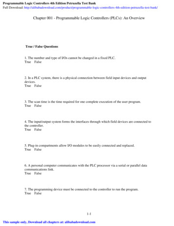
1Programmable LogicControllers (PLCs)An OverviewPhoto courtesy Rockwell Automation, Inc.Chapter ObjectivesAfter completing this chapter, you will be able to:1.1Define what a programmable logic controller (PLC) isand list its advantages over relay systems1.2Identify the main parts of a PLC and describe theirfunctions1.3Outline the basic sequence of operation for a PLC1.4Identify the general classifications of PLCsThis chapter gives a brief history of the evolutionof the programmable logic controller, or PLC.The reasons for changing from relay control systems to PLCs are discussed. You will learn thebasic parts of a PLC, how a PLC is used to control a process, and the different kinds of PLCsand their applications. The ladder logic language,which was developed to simplify the task of programming PLCs, is introduced.Each chapter begins with a briefintroduction outlining chapter coverageand learning objectives.1
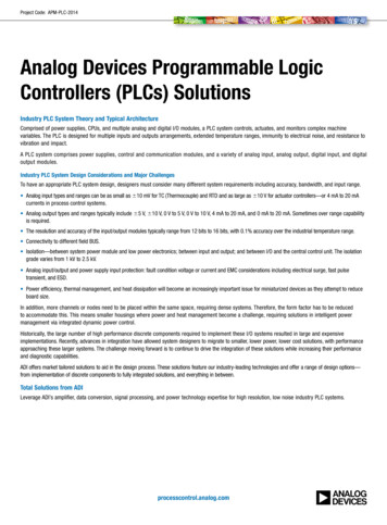
Figure 2-49 Human Machine Interfaces (HMIs).Source: Photo courtesy Omron Industrial Automation, www.ia.omron.com.time. Through personal computer–based setup software,you can configure display screens to: Replace hardwired pushbuttons and pilot lightswith realistic-looking icons. The machine operatorneedonly touchthe displayinterfacingpanel to activatethe PicoHumanmachinewithpushbuttons. Show operations in graphic format for easier viewing. Allow the operator to change timer and counter presets by touching the numeric keypad graphic on thetouch screen. Show alarms, complete with time of occurrence andlocation. Display variables as they change over time.The Allen-Bradley Pico GFX-70 controller, shown inFigure 2-50, serves as a controller with HMI capabilities.Figure 2-50 Allen-Bradley Pico GFX-70 controller.Source: Photo courtesy Rockwell Automation, Inc.controllers added.This device consists of three modular parts: an HMI,processor/power supply, and I/O modules.The display/keypad can be used as an operator interface or can be linked to control operations to provide realtime feedback. It has the ability to show text, date andtime, as well as custom messages and bitmap graphics,allowing operators to acknowledge fault messages, entervalues, and initiate actions. Users can create both thecontrol program and HMI functionality using a personalcomputer with PicoSoft Pro software installed or the controller’s on-board display buttons.PLC Hardware Components Chapter 239
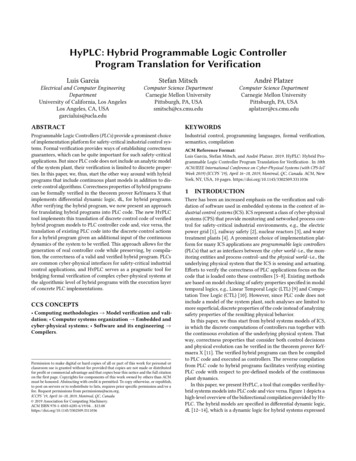
Output module Each connected output has a bit in the output imagetable file that corresponds exactly to the terminal towhich the output is connected. If the program calls for a specific output to be ON,its corresponding bit in the table is set to 1. If the program calls for the output to be OFF, itscorresponding bit in the table is set to 0. The processor continually activates or deactivates theoutput status according to the output table file status.L2OFFON0Typically, micro PLCs have a fixed number of inputsand outputs. Figure 5-6 shows the MicroLogic controller from the Allen-Bradley MicroLogic 1000 family ofcontrollers. The controller has 20 discrete inputs withpredefined addresses I/0 through I/19 and 12 discreteoutputs with predefined addresses O/1 through O/11.Some units also contain analog inputs and outputs embedded into the base unit or available through add-onmodules.1Word correspondingto output moduleOutput image5.2Data tablefilesWhen a PLC executes a program, it must know—in realtime—when external devices controlling a process arechanging. During each operating cycle, the processorreads all the inputs, takes these values, and energizes orde-energizes the outputs according to the user program.This process is known as a program scan cycle. Figure 5-7illustrates a single PLC operating cycle consisting of theinput scan, program scan, output scan, and housekeeping duties. Because the inputs can change at any time, itconstantly repeats this cycle as long as the PLC is in theRUN mode.Figure 5-5 Connections of pilot lights to the output imagetable file through the output module.connection of two pilot lights to the output image tablefile through the output module. Its operation can be summarized as follows. The status of each light (ON/OFF) is controlled bythe user program and is indicated by the presence of1 (ON) and 0 (OFF).L1L2ACCOMI/0I/1I/2I/3ACCOMVACVDC O/0CRL1L2Discrete InputsL2I/4I/5VACVDCO/4I/6I/9I/10Program ScanL1I/7I/8I/11I/12VACVDC O/2O/3VACVDC O/4O/5O/6O/7VACVDC O/8CRCRCRCRCRCRVAC 2 VDC 1VDC 2VAC 2VDC 1COMCOMI/13I/14I/15VDC 3VDC 2COMI/16I/17I/18I/19O/9 O/10 O/11CRCRCRVDC 3COMDiscrete OutputsFigure 5-6 Typical micro PLC with predefined addresses.Source: Photo courtesy Rockwell Automation, Inc.76Chapter 5 Basics of PLC ProgrammingAddressing of a micro PLC illustrated.
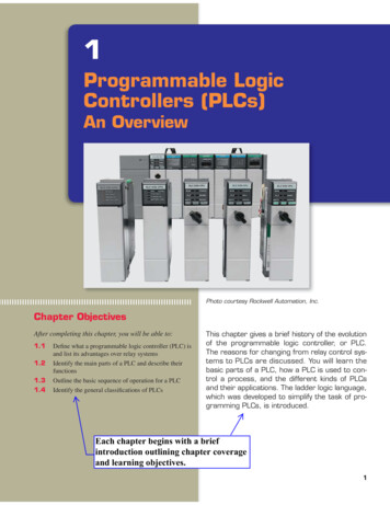
InputmoduleInputdeviceΙ:3/6Processor epower supplyField-devicepower supplyΙ:3/6O:4/7ProgramFigure 5-9 Scan process applied to a single rung program. During the program scan, the processor examinesbit I:3/6 for a 1 (ON) condition. In this case, because input I:3/6 is 1, the rung is saidto be TRUE or have logic continuity. The processor then sets the output image table bitO:4/7 to 1. The processor turns on output O:4/7 during the nextI/O scan, and the output device (light) wired to thisterminal becomes energized. This process is repeated as long as the processor isin the RUN mode. If the input device opens, electrical continuity islost, and a 0 would be placed in the input imagetable. As a result, the rung is said to be FALSE dueto loss of logic continuity. The processor would then set the output image tablebit O:4/7 to 0, causing the output device to turn off.Ladder programs process inputs at the beginning of ascan and outputs at the end of a scan, as illustrated in Figure 5-10. For each rung executed, the PLC processor will:Step 1 Update the input image table by sensing thevoltage of the input terminals. Based on theabsence or presence of a voltage, a 0 or a 1 isstored into the memory bit location designatedfor a particular input terminal.Step 2 Solve the ladder logic in order to determinelogical continuity. The processor scans the ladder program and evaluates the logical continuity of each rung by referring to the input imagetable to see if the input conditions are met. Ifthe conditions controlling an output are met, theprocessor immediately writes a 1 in its memorylocation, indicating that the output will beturned ON; conversely, if the conditions are notmet a 0 indicating that the device will be turnedOFF is written into its memory location.78Chapter 5 Basics of PLC ProgrammingStep 3 The final step of the scan process is to updatethe actual states of the output devices by transferring the output table results to the outputmodule, thereby switching the connected output devices ON (1) or OFF (0). If the status ofany inputdevicesexplainedchanges wheninthe processorProgram scanprocessisinstep2or3,theoutput condition will notgreater detail.react to them until the next processor scan.Each instruction entered into a program requires a certain amount of time for the instruction to be executed. Theamount of time required depends on the instruction. Forexample, it takes less time for a processor to read the status of an input contact than it does to read the accumulated value of a timer or counter. The time taken to scanInput image table0 0 0 1 0 0 0 1 0 0 1 0 0 0 1 0STARTStep 1ReadinputmoduleStep 2Solve theladder programEND0 0 0 0 0 0 0 0 0 0 0 1 0 0 1 0Output image tableStep 3Transferto outputmoduleFigure 5-10 Scan process applied to a multiple rungprogram.
L1Wiring of field inputsand outputs to a microPLC illustrated.Motor/controllerStopL2L1 L2StartI1 SpeedfeedbackQ1ServomotorQ1MTachometer: speedEncoder: positionSource: Photos courtesy Omron Industrial Automation, www.ia.omron.com.The motor stop/start circuit shown in Figure 6-44 is atypical example of a seal-in circuit. The hardwired circuitconsists of a normally closed stop button in series with anormally open start button. The seal-in auxiliary contactof the starter is connected in parallel with the start buttonto keep the starter coil energized when the start button isreleased. When this circuit is programmed into a PLC,both the start and stop buttons are examined for a closedcondition because both buttons must be closed to causethe motor starter to operate.Figure 6-45 shows a PLC wiring diagram of the motorseal-in circuit implemented using an Allen-Bradley Picocontroller. The controller is programmed using ladderlogic. Each programming element can be entered directlyStopMotorL2starter coilL1Q3Motorstarter coilvia the Pico display. This controller also lets you programthe circuit from a personal computer using PicoSoft programming software.6.9Latching RelaysElectromagnetic latching relays are designed to hold therelay closed after power has been removed from the coil.Latching relays are used where it is necessary for contactsto stay open and/or closed even though the coil is energized only momentarily. Figure 6-46 shows a latchingrelay that uses two coils. The latch coil is momentarilyenergized to set the latch and hold the relay in the latchedposition. The unlatch or release coil is momentarilyInputsLadder logic programStopMMQ1Figure 6-45 Motor seal-in circuit implemented using anAllen-Bradley Pico controller.Figure 6-43 Closed-loop servo motor StopStartSeal-in contactOutputMotorstartercoilL2MMotorstarter coilMHardwiredProgrammedFigure 6-44 Hardwired and programmed seal-in circuit.Developing Fundamental PLC Wiring Diagrams and Ladder Logic Programs Chapter 6111
Ladder logic programMan/AutoLow sensor switch /1I:2/0B3:0/0Man/AutoHigh sensor switchLatch coilLI:2/4I:2/12B3:0/0Man/AutoLow sensor switchUnlatch Low sensor switchRI:2/8O:3/9High sensor switchYI:2/12Wiring of field inputsand outputs to a SLC 500PLC illustrated.O:3/1301Slots2 3 456PowersupplyInput module0123456789101112131415Output module24 VDC16 point discreteinput moduleField devicepower supplyL2240 VACL10123456789101112131415240 VAC16 point discreteoutput moduleOFF ONIN 0IN 1IN 2ManAutoMIN 5IN 6IN 10Low levelROUT 2OUT 3OUT 4OUT 5OUT 6OUT 7OUT 8OUT 9OUT 10IN 11IN 12IN 13 DC DCField devicepower supplyOUT 0OUT 1IN 7IN 8IN 1424 VDCPump runningGIN 9High sensorswitchVACIN 3IN 4Low sensorswitchMotorDC IN 15COM DCCOMHigh levelYOUT 11OUT 12OUT 13OUT 14OUT 15ACCOMFigure 6-52 Water level control program implemented using an Allen-Bradley modular SLC 500 controller.Developing Fundamental PLC Wiring Diagrams and Ladder Logic Programs Chapter 6115
EXAMPLE 6-3Figure 6-67 shows the sketch of a continuous filling operation. This process requires that boxes moving on a conveyor be automatically positioned and filled.The sequence of operation for the continuous filling operation is as follows: Start the conveyor when the start button is momentarily tch Stop the conveyor when the stop button is momentarily pressed. Energize the run status light when the process isoperating. Energize the standby status light when the process isstopped. Stop the conveyor when the right edge of the box isfirst sensed by the photosensor.Photoswitch With the box in position and the conveyor stopped,open the solenoid valve and allow the box to fill. Fillingshould stop when the level sensor goes true.MotorStartStop Energize the full light when the box is full. The full lightshould remain energized until the box is moved clearof the photosensor.Figure 6-67 Sketch of the continuous filling operation.Figure 6-68 shows the ladder logic programrequiredofforprogramsExamplesthe operation.includea sketch of the process.InputsStopLadder logic e 6-68 Continuous filling operation PLC program.Developing Fundamental PLC Wiring Diagrams and Ladder Logic Programs Chapter 6121
MagneticstarterPLCContactorDrawings andphotos of realworld field inputL1and outputdevices havebeen added.OverloadrelayMotorPushbuttonsOutputInputsPLC ProgramStart StopOLL2StartercoilStartMMStopMOLFigure 6-9 PLC control of a motor.Figure 6-7 Motor starter is a contactor with an attachedoverload relay.Source: Photo courtesy Rockwell Automation, Inc. Control contact M (across START button) closesto seal in the coil circuit when the START button isreleased. This contact is part of the control circuitand, as such, is only required to handle the smallamount of current needed to energize the coil. An overload (OL) relay is provided to protect themotor against current overloads. The normallyclosed relay contact OL opens automatically whenOLMMagnetic starterMLow-currentcontrol circuitOLL1T1MOLMOLL2Motor starters are available in various standard National Electric Manufacturers Association (NEMA) sizesand ratings. When a PLC needs to control a large motor,it must work in conjunction with a starter as illustrated inFigure 6-9. The power requirements for the starter coilmust be within the power rating of the output module ofthe PLC. Note that the control logic is determined andexecuted by the program within the PLC and not by thehardwired arrangement of the input control devices.6.4StartStopMan overload current is sensed to de-energize the Mcoil and stop the motor.ThreephasemotorT2T3L3High-currentpower circuitFigure 6-8 Three-phase magnetic motor starter.Source: This material and associated copyrights are proprietary to, and usedwith the permission of Schneider Electric.Manually Operated SwitchesManually operated switches are controlled by hand.These include toggle switches, pushbutton switches, knifeswitches, and selector switches.Pushbutton switches are the most common form ofmanual control. A pushbutton operates by opening or closing contacts when pressed. Figure 6-10 shows commonlyused types of pushbutton switches, which include: Normally open (NO) pushbutton, which makes acircuit when it is pressed and returns to its open position when the button is released. Normally closed (NC) pushbutton, which opens thecircuit when it is pressed and returns to the closedposition when the button is released. Break-before-make pushbutton in which the topsection contacts are NC and the bottom section contacts are NO. When the button is pressed, the topcontacts open before the bottom contacts are closed.Developing Fundamental PLC Wiring Diagrams and Ladder Logic Programs Chapter 699
Hardwired relay circuitL1StopL2StartTDThe relay equivalent of thevirtual programmedinstruction is explained first,followed by the appropriatePLC program.TD-1MTD-2(5 s)Ladder logic otorStartInternalrelayMMotorMTimerPR: 5TB: 1 sOutput lineFigure 7-17 Instantaneous contact instruction can be programmed using aninternally referenced relay coil. Contact TD-1 is the instantaneous contact, and contact TD-2 is the timed contact. The ladder logic program shows that a contact instruction referenced to an internal relay is now usedto operate the timer. The instantaneous contact is referenced to the internal relay coil, whereas the time-delay contact isreferenced to the timer output coil.Figure 7-18 shows an application for an on-delay timerthat uses an NCTO contact. This circuit is used as a warning signal when moving equipment, such as a conveyormotor, is about to be started. The operation of the circuitcan be summarized as follows: According to the hardwired relay circuit diagram,coil CR is energized when the start pushbutton PB1is momentarily actuated. As a result, contact CR-1 closes to seal in CR coil,contact CR-2 closes to energize timer coil TD,and contact CR-3 closes to sound the horn. After a 10-s time-delay period, timer contact TD-1opens to automatically switch the horn off. The ladder logic program shows how an equivalentcircuit could be programmed using a PLC.132Chapter 7Programming Timers The logic on the last rung is the same as the timertiming bit and as such can be used with timers thatdo not have a timer-timing output.Timers are often used as part of automatic sequentialcontrol systems. Figure 7-19 shows how a series of motors can be started automatically with only one start/stopcontrol station. The operation of the circuit can be summarized as follows: According to the relay ladder schematic, lube-oilpump motor starter coil M1 is energized when thestart pushbutton PB2 is momentarily actuated. As a result, M1-1 control contact closes to seal inM1, and the lube-oil pump motor starts. When the lube-oil pump builds up sufficient oilpressure, the lube-oil pressure switch PS1 closes. This in turn energizes coil M2 to start the maindrive motor and energizes coil TD to begin the timedelay period. After the preset time-delay period of 15 s, TD-1contact closes to energize coil M3 and start the feedmotor. The ladder logic program shows how an equivalentcircuit could be programmed using a PLC.
L1InputsPBOutputI:1/0I:1/0B3:0/0TODTo IMER ON DELAYTimerTime 1011121314150000Figure 8-19 OSR instruction used to freeze rapidly displayed LED values. When the timer is running, SW (I:1/1) closed, theaccumulated value changes rapidly. Closing the momentary pushbutton PB (I:1/0) willfreeze and display the value at that point in time.with the programmed timed oscillator circuit studied inChapter 7. The operation of the program can be summarized as follows:The alarm monitor PLC program of Figure 8-20 illustrates the application of an up-counter used in conjunctionInputsLadder logic programT4:6L1DNFST4:5DNFSOFF The alarm is triggered by the closing of float switch FS. The light will flash whenever the alarm conditionis triggered and has not been acknowledged,OutputL2TONTIMER ON DELAYTimerTime basePresetAccumulatedT4:51.010TONTIMER ON DELAYTimerTime CUDNLightDNFSDNSSFigure 8-20 Alarm monitor program.158Chapter 8 Programming CountersLightENCTUCOUNT-UP awings and photos of realworld field input and outputdevices have been added tothe logic diagrams.
File type5Counter numberC5:3CountersFile numberCounter addressC5:3C5:3.0C5:3.1C5:3.2Bit15 14 13 12 11 10 09 08 07 06 05 04 03 02 01 00WordCU CD DN OV UN UA0WordPreset value1WordAccumulated value2Internal use (not addressable)Figure 8-9 SLC 500 counter file.C5:3/UA is the address for the update accumulator bit Each false-to-true transition of rung 1 increases theof the counter.counter’s accumulated value by 1. After 7 pulses, or counts, when the preset counterFigure 8-10 shows the counter table for the Allenvalue equals the accumulated counter value, outputBradley SLC 500 controller. The control word uses statusDN is energized.control bits consisting of the following: As a Althoughresult, rung 2 thebecomestrue andcontentis energizesof a nature to allow the information to beCount-Up (CU) Enable Bit—The count-up enoutputO:2/0 to switchthe red pilotlight on.from differentappliedto a varietyof PLCsthis bookable manufacturers,bit is used with the count-upcounter and is true At the same time, rung 3 becomes false and defor the most part uses the Allen-BradleywheneverSLC-500ControlLogixthe andcount-upcounter instruction is true. Ifenergizes output O:2/1 to switch the green pilotthe count-upcounter instruction is false, the CU bitinstruction sets for the programmingexamples.light controlleroff.is false. The counter is reset by closing pushbutton PB2,Count-Down (CD) Enable Bit—The count-downwhich makes rung 4 true and resets the accumulatedenable bit is used with the count-down counter and iscount to zero.true whenever the count-down counter instruction is Counting can resume when rung 4 goes false again.true. If the count-down counter instruction is false, theThe Allen-Bradley SLC 500 counter file is file 5 (Figure 8-9). Each counter is composed of three 16-bit words,collectively called a counter element. These three datawords are the control word, preset word, and accumulatedword. Each of the three data words shares the same baseaddress, which is the address of the counter itself. Therecan be up to 256 counter elements. Addresses for counterfile 5, counter element 3 (C5:3), are listed below.C5 5 counter file 5:3 5 counter element 3 (0–255 counter elements perfile)C5:3/DN is the address for the done bit of the counter.C5:3/CU is the address for the count-up enable bit ofthe counter.C5:3/CD is the address for the count-down enable bitof the counter.C5:3/OV is the address for the overflow bit of thecounter.C5:3/UN is the address for the underflow bit of thecounter.CD bit is false.Done (DN) Bit—The done bit is true whenever theaccumulated value is equal to or greater than the preset value of the counter, for either the count-up or thecount-down counter.Overflow (OV) Bit—The overflow bit is true whenever the counter counts past its maximum value,which is 32,767. On the next count, the counter willwrap around to 32,768 and will continue countingCounter CD000000/DN000000/OV000000/UN000000/UA000000.PRE .ACC0000005000000Table: C5: CounterFigure 8-10 SLC 500 counter table.Programming Counters Chapter 8153
1237810591164127Figure 9-24 Safety PLC.Source: Image Used with Permission of Rockwell Automation, Inc.Safety PLCs, such as the one shown in Figure 9-24,are now available for applications that require more advanced safety functionality. A safety PLC is typicallycertified by third parties to meet rigid safety and reliability requirements of international standards. Both standard and safety PLCs have the ability to perform controlfunctions but a standard PLC was not initially designedto be fault tolerant and fail-safe. That is the fundamentaldifference.Some of the differences between standard and safetyPLCs include the following: A standard PLC has one microprocessor thatexecutes the program, Flash memory area thatstores the program, RAM for making calculations, ports for communications, and I/O fordetection and control of the machine. In contrast,a safety PLC has redundant microprocessors,Flash and RAM that are continuously monitored by a watchdog circuit, and a synchronousdetection circuit. Redundancy is duplication. Theprobability of hazards arising from one malfunction in an electrical circuit can be minimizedby creating partial or complete redundancy(duplication). Standard PLC inputs provide no internal means fortesting the functionality of the input circuitry. Bycontrast, safety PLCs have an internal output circuitassociated with each input for the purpose of testingthe input circuitry. Inputs are driven both high andlow for very short cycles during runtime to verifytheir functionality.192Chapter 9 Program Control InstructionsNumber123456789101112FeatureModule status indicatorsAlphanumeric displayNode address switchesBaud rate switchesUSB portDeviceNet communication connectorTerminal connectorsInput status indicatorsOutput status indicatorsIP address desplay switchEthernet connectorService switchThe content has been updated and reflects thechanges in technology since the publication ofthe previous edition. Safety PLCs use power supplies designed specifically for use in safety control systems and redundant backplane circuitry between the controller andI/O modules.Safety considerations should be developed as partof the PLC program. A PLC program for any application will be only as safe as the time and thought spenton both personnel and hardware considerations makeit. One such consideration involves the use of a motorstarter auxiliary seal-in contact, shown in Figure 9-25,in place of the programmed contact referenced to theoutput coil instruction. The use of the field-generatedstarter auxiliary contact status in the program is morecostly in terms of field wiring and hardware, but it issafer because it provides positive feedback to the processor about the exact status of the motor. Assume,for example, that the OL contact of the starter opensunder an overload condition. The motor, of course,would stop operating because power would be lost tothe starter coil. If the program was written using anexamine-on contact instruction referenced to the output coil instruction as the seal-in for the circuit, theprocessor would never know that power had been lostto the motor. When the OL was reset, the motor wouldrestart instantly, creating a potentially unsafe operatingcondition.Another safety consideration concerns the wiringof stop buttons. A stop button is generally considereda safety function as well as an operating function. Assuch, all stop buttons should be wired using a normally closed contact programmed to examine for an on
Analog outputPLCUltrasoniclevel blevalveMeasurement ofvariable to gure 10-42 Closed-loop control system.4 to 20 mAanalog inputFigure 10-43 Proportional control process.the output to degrade closing the valve by different percentages, adjusting the valve to maintain a set-point.Proportional-integral-derivative (PID) control is themost sophisticated and widely used type of process control.PID operations are more complex and are mathematicallybased. PID controllers produce outputs that depend on themagnitude, duration, and rate of change of the system errorsignal. Sudden system disturbances are met with an aggressive attempt to correct the condition. A PID controller canreduce the system error to 0 faster than any other controller.A typical PID control loop is illustrated in Figure 10-44.The loop measures the process, compares it to a set-point,and then manipulates the output in the direction whichshould movethe processtoward theset-point. The termicontrolcoveredin moredetail.nology used in conjunction with a PID loop can be summarized as follows:(error) exists between the actual and desired levels, thePLC control program will take the necessary correctiveaction. Adjustments are made continuously by the PLCuntil the difference between the desired and actual outputis as small as is practical.With on/off PLC control (also known as two-positionand bang-bang control), the output or final control element is either on or off—one for the occasion when thevalue of the measured variable is above the set-point andAnalogthe other for the occasion when the value is belowtheset-point. The controller will never keep the final controlelement in an intermediate position. Most residential thermostats are on/off type controllers. Operating information that the controller receivesOn/off control is inexpensive but not accurate enoughfrom the machine is called the process variablefor most process and machine control applications. On/(PV) or feedback.off control almost always means overshoot and resultant Input from the operator that tells the controller thesystem cycling. For this reason a deadband usually exdesired operating point is called the set-point (SP).ists around the set-point. The deadband or hysteresis of When operating, the controller determines whetherthe control loop is the difference between the on and offthe machine needs adjustment by comparing (byoperating points.subtraction) the set-point and the process variableProportional controls are designed to eliminate thehunting or cycling associated with on/off control. TheyErrorSet-pointΣPID equationallow the final control element to take intermediate po(SP)Flowsitions between on and off. This permits analog controlProcessrateLevelof the final control element to vary the amount of energyvariabledetectorControl(PV)to the process, depending on how much the value of thevariable(CV)measured variable has shifted from the desired value.The process illustrated in Figure 10-43 is an exampleof a proportional control process. The PLC analog outputmodule controls the amount of fluid placed in the holdingtank by adjusting the percentage of valve opening. Thevalve is initially open 100 percent. As the fluid level in thetank approaches the preset point, the processor modifiesFigure 10-44 Typical PID control loop.220Chapter 10 Data Manipulation Instructions
Length—Is the number of steps of the sequencer filestarting at position 1. Position 0 is the start-up position. The instruction resets (wraps) to position 1 ateach cycle completion. The actual file length will be1 plus the file length entered in the instruction.Position—Indicates the step that is desired to startthe sequencer instruction. The position is the wordlocation or step in the sequencer file from which theinstruction moves data. Any value up to the file lengthmay be entered, but the instruction will always resetto 1 on the true-to-false transition after the instruction has operated on the last position. Before we startthe sequence, we need a starting point at which thesequencer is in a neutral position. The start position isall zeros, representing this neutral position; thus, alloutputs will be off in position 0.requirements of the control application. As the sequenceradvances through the steps, binary information is transferred from the sequencer file to the output word.To illustrate the purpose and function of the sequencerfile we will examine the operation of the four-step sequence process shown in Figure 12-8. This sequencer is tobe used to control traffic in two directions. The operationof the process can be summarized as follows: Six outputs are to be energized from one 16-pointoutput module. Each light is controlled by one bit address of outputword O:2. The first 6 bits are programmed to execute
Programmable Logic Controllers (PLCs) An Overview This chapter gives a brief history of the evolution of the programmable logic controller, or PLC. The reasons for changing from relay control sys-tems to PLCs are discussed. You will learn the basic parts of a PLC, how a PLC is used to con-trol a process, and the different kinds of PLCs