Transcription
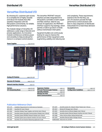
Distributed I/OVersaMax Distributed I/OVersaMax Distributed I/OBy choosing GE, customers gain accessto a complete line of highly versatileand robust I/O modules that offerseamless integration with thePACSystems control family, for reliable,high performance solutions.The modular design of VersaMax I/Oaddresses a wide range of discrete andprocess applications. Its innovativemodular architecture combines powerand versatility to help provide performance in a compact control solution.Power SuppliesAnalog I/O ModulesDiscrete I/O Modulesand complexity. These requirementsextend to the I/O that they use.GE’s I/O solutions provide the highperformance control solutions withbest-in-class integration of distributed(networked) I/O to meet these demanding applications.Equipment builders are continuouslylooking for ways to improve theperformance of their equipment whileaugmenting usability and reducing sizepages 4.89-4.90pages 4.104-4.108pages 4.91-4.103Network Interface ModulesCarriersI/O Interposing BasesThe VersaMax PROFINET networkinterface provides integrated I/O toPACSystems controllers in both copperand fiber interface. Ideal for anyremote I/O application, the PROFINETinterface supports ring topology, whichpermits a node to go down or breakwithout transmission interruption.page 4.114pages 4.84-4.86pages 4.87-4.88Expansion Modulespage 4.111RTD and Thermocouple Modulespage 4.109Specialty Modulespage 4.110Remote I/O Unitspages 4.112-4.113Serial Communicationspage 4.115AccessoriesConfiguration Guidelinespage 4.116pages 4.117-4.118Publication Reference ChartGFK-1179Installation Requirements for Conformance to StandardsGFK-1697VersaMax System AS-i Network Master Module User’s ManualGFK-1503VersaMax PLC User’s ManualGFK-1847Remote I/O Manager User’s ManualGFK-1504VersaMax Modules, Power Supplies, and Carriers User’s ManualGFK-1852VersaMax Serial to Ethernet Adapter User’s ManualGFK-1533VersaMax System DeviceNet Communications Modules User’s ManualGFK-1860VersaMax System Ethernet Network Interface Unit User’s ManualGFK-1534VersaMax System PROFIBUS Network Modules User’s ManualGFK-1868Proficy Machine Edition Getting Started GuideGFK-1535VersaMax System Genius Network Interface Unit User’s ManualGFK-1876VersaMax Ethernet Station Manager ManualVersaMax I/O and Industrial Networking Application GuideIC690CDU002 InfoLink for PLC CD-ROMGFK-1563www.ge-ip.comGE Intelligent Platforms Control Systems Solutions4.83
VersaMax Distributed I/ODistributed I/OCarriersVersaMax provides several types of snap-together I/O carriers and interposing terminalsto provide maximum wiring flexibility, as well as module hot insertion and removal.VersaMax carriers support IEC box-style, spring-style, and barrier-style terminals and arealso available as snap-on auxiliary terminal strips and interposing terminals that can bemounted separately and connected to a connector-style carrier by an I/O cable.IC200CHS022IC200CHS025Product NameVersaMax Compact I/O Carrier,Local Box Clamp Connection StyleVersaMax Compact I/O Carrier,Local Spring Clamp Connection StyleLifecycle StatusActiveActiveField Termination TypeIntegratedIntegratedWiring Termination StyleLocal BoxLocal SpringOrientation on Module on BaseDimensions (W x H x D)VerticalVertical66.8 mm (2.63 in) x 163.5 mm (6.45 in) x 70 mm (2.75 in),not including the height of DIN-rail66.8 mm (2.63 in) x 163.5 mm (6.45 in) x 70 mm (2.75 in),not including the height of DIN-railN/AN/ACables4.84GE Intelligent Platforms Control Systems Solutionswww.ge-ip.com
Distributed I/OVersaMax Distributed I/OCarriersVersaMax provides several types of snap-together I/O carriers and interposing terminals toprovide maximum wiring flexibility, as well as module hot insertion and removal. VersaMaxcarriers support IEC box-style, spring-style, and barrier-style terminals and are also available as snap-on auxiliary terminal strips and interposing terminals that can be mountedseparately and connected to a connector-style carrier by an I/O cable.IC200CHS001IC200CHS002IC200CHS005Product NameVersaMax I/O Carrier,Local Barrier StyleVersaMax I/O Carrier,Local Box StyleVersaMax I/O Carrier,Local Spring ClampConnection StyleLifecycle 110.5 mm (4.35 in) x139.7 mm (5.5 in) x70 mm (2.75 in),not including theheight of DIN-rail110.5 mm (4.35 in) x139.7 mm (5.5 in) x70 mm (2.75 in),not including theheight of DIN-rail110.5 mm (4.35 in) x139.7 mm (5.5 in) x70 mm (2.75 in),not including theheight of DIN-railN/AN/AN/AField Termination TypeWiring Termination StyleOrientation on Module on BaseDimensions (W x H x D)Cableswww.ge-ip.comGE Intelligent Platforms Control Systems Solutions4.85
VersaMax Distributed I/ODistributed I/OCarriersVersaMax provides several types of snap-together I/O carriers and interposingterminals to provide maximum wiring flexibility, as well as module hot insertionand removal. VersaMax carriers support IEC box-style, spring-style, and barrierstyle terminals and are also available as snap-on auxiliary terminal strips andinterposing terminals that can be mounted separately and connected to aconnector-style carrier by an I/O IC200CHS015VersaMax I/O Carrier,Interposing Box Style(Requires IC200CHS003base and connectingcable IC200CBL1xxx)VersaMax I/O Carrier,Interposing BoxThermocoupleCompensation(Requires IC200CHS003base and connectingcable IC200CBL1xxx)VersaMax I/O Carrier,Interposing Spring Clamp(Requires IC200CHS003base and connectingcable IC200CBL1xxx)VersaMax I/O Carrier,Interposing Spring Clamp(Requires IC200CHS003base and connectingcable IC200CBL1xxx)Product NameVersaMax I/O Carrier,VersaMax I/O Carrier,Connector Style. InterposingBarrier A connecting cable Style(Requires (IC200CBL1xxx) andIC200CHS003 base interposingbase (IC200CHS011, andconnecting CHS012, CHS014,CHS015, cable IC200CBL1xxx)IC200CHS1xx or IC200CHS2xx)are required. This carrier can beused with all VersaMax I/Omodules EXCEPT the following,due to their high isolationrequirements: IC200MDL144Input 240 VAC 4 Point IsolatedModule; IC200MDL244 Input 240VAC 8 Point Isolated Module;IC200MDD850 Mixed 240 VACIsolated 4 Point / Output Relay2.0A Isolated 8 Point ModuleLifecycle gVerticalN/AN/AN/AN/ADimensions (W x H x D)66.8 mm (2.63 in) x133.4 mm (5.25 in) x70 mm (2.75 in),not including theheight of DIN-rail110.5 mm (4.35 in) x105.4 mm (2.63 in) x70 mm (2.75 in),not including theheight of DIN-rail110.5 mm (4.35 in) x105.4 mm (2.63 in) x70 mm (2.75 in),not including theheight of DIN-rail110.5 mm (4.35 in) x105.4 mm (2.63 in) x70 mm (2.75 in),not including theheight of DIN-rail110.5 mm (4.35 in) x105.4 mm (2.63in) x70 mm (2.75 in),not including theheight of DIN-railCablesRequires aIC200CBL1xxx cableRequires aIC200CBL1xxx cableRequires aIC200CBL1xxx cableRequires aIC200CBL1xxx cableRequires aIC200CBL1xxx cableField Termination TypeWiring Termination StyleOrientation onModule on Base4.86GE Intelligent Platforms Control Systems Solutionswww.ge-ip.com
Distributed I/OVersaMax Distributed I/OI/O Interposing BasesVersaMax I/O interposing disconnect bases enable the IC200CHS003 to connect to awide range of termination bases. The Relay bases provide additional protection andhigher amperage outputs. The Disconnect bases enables the user to easily disconnectsignals, on a per point bases, from the I/O 1Product NameVersaMax I/O Carrier,Connector Style.A connecting cable(IC200CBL1xxx) andinterposing base(IC200CHS011, CHS012,CHS014, CHS015, IC200CHS1xxor IC200CHS2xx) are required.This carrier can be used withall VersaMax I/O modulesEXCEPT the following, dueto their high isolationrequirements: IC200MDL144Input 240 VAC 4 Point IsolatedModule; IC200MDL244 Input240 VAC 8 Point IsolatedModule; IC200MDD850Mixed 240 VAC Isolated4 Point / Output Relay 2.0AIsolated 8 Point ModuleInput or Output InterposingDisconnect Style 16 Points.The base has an individualknife-switch disconnectfor each signal and commonterminal and its correspondingpin on the VersaMax cableconnector. RequiresIC200CHS003 and a connectingcable IC200CBL1xxx.Expansion Input or OutputInterposing Disconnect Style16 Points. The base has anindividual knife-switchdisconnect for each signaland common terminal andits corresponding pin on theVersaMax cable connector.Requires a IC200CHS101 mainbase, can not be directlyconnected to IC200CHS003.I/O Interposing Relay Base(replaceable relays), fused(8 amps, replaceable), 16 points.The relays on these interposingterminals are intended tobe controlled with standard24 VDC 0.5A VersaMax outputmodules (IC200MDL740 andIC200MDL750 usingIC200CHS003 base andconnected by IC200CBL1xxx).Lifecycle StatusActiveActiveActiveActiveField Termination gratedWiring Termination StyleConnectorBoxBoxBoxRemovable Terminals ConnectorsN/ANoNoNoN/AAll discrete modules supportedexcept MDL144, 244, 331, 730and MDD840, 843, 850.All discrete modules supportedexcept MDL144, 244, 331, 730and MDD840, 843, 850.24 VDC from MDL740and MDL750N/AAll discrete modules supportedexcept MDL144, 244, 331, 730and MDD840, 843, 850.All discrete modules supportedexcept MDL144, 244, 331, 730and MDD840, 843, 850.0-125 VDC, 5/24/125 VDCnominal; 0-265 VAC (47-63 Hz),120/240 VAC nominalN/AN/AN/A8.0 A for 5-265 VAC,2.0 A for 5-30 VDC,0.2 A for 31-125 VDC(Replaceable Fuse)N/AN/AN/AReplaceable FuseInput VoltageOutput VoltageLoad Current per PointProtectionPoints per CommonDimensions (W x H x D)Cableswww.ge-ip.comN/AN/AN/AIsolated Per Point66.8 mm (2.63 in) x 133.4 mm(5.25 in) x 70 mm (2.75 in),not including theheight of the DIN-rail115 mm (4.5 in) x 126 mm(4.95 in) x 65 mm (2.6 in),not including theheight of the DIN-rail115 mm (4.5 in) x 126 mm(4.95 in) x 65 mm (2.6 in),not including theheight of the DIN-rail253.7 mm (9.9 in) x 126 mm(4.95 in) x 73 mm (2.8 in),not including theheight of the DIN-railRequires aIC200CBL1xxx cableRequires aIC200CBL1xxx cableN/ARequires aIC200CBL1xxx cableGE Intelligent Platforms Control Systems Solutions4.87
VersaMax Distributed I/ODistributed I/OI/O Interposing BasesVersaMax I/O interposing disconnect bases enable the IC200CHS003 to connect to awide range of termination bases. The Relay bases provide additional protection andhigher amperage outputs. The Disconnect bases enables the user to easily disconnectsignals, on a per point bases, from the I/O module.IC200CHS112IC200CHS211IC200CHS212I/O Interposing Relay Base(replaceable relays), fused(8 amps, replaceable), 16 points.The relays on these interposingterminals are intended to becontrolled with standard 24 VDC0.5A VersaMax output modules(IC200MDL740 and IC200MDL750using IC200CHS003 base andconnected by IC200CBL1xxx).Expansion base.I/O Interposing Relay Base(replaceable relays), fused(8 amps, replaceable), 16 points.Field terminals are removable.The relays on these interposingterminals are intended to becontrolled with standard 24 VDC0.5A VersaMax output modules(IC200MDL740 and IC200MDL750using IC200CHS003 base andconnected by IC200CBL1xxx).I/O Interposing Relay Base(replaceable relays), fused(8 amps, replaceable), 16 points.Field terminals are removable.The relays on these interposingterminals are intended to becontrolled with standard 24 VDC0.5A VersaMax output modules(IC200MDL740 and IC200MDL750using IC200CHS003 base andconnected by IC200CBL1xxx).Expansion dNon-IntegratedConnection StyleBoxBoxBoxRemovable Terminals ConnectorsNoYesYes24 VDC from MDL740and MDL75024 VDC from MDL740and MDL75024 VDC from MDL740and MDL7500-125 VDC, 5/24/125 VDC nominal;0-265 VAC (47-63 Hz),120/240 VAC nominal0-125 VDC, 5/24/125 VDC nominal;0-265 VAC (47-63 Hz),120/240 VAC nominal0-125 VDC, 5/24/125 VDC nominal;0-265 VAC (47-63 Hz),120/240 VAC nominal8.0 A for 5-265 VAC, 2.0 A for 5-30 VDC, 0.2A for 31-125 VDC (Replaceable Fuse)8.0 A for 5-265 VAC, 2.0 A for 5-30 VDC, 0.2A for 31-125 VDC (Replaceable Fuse)8.0 A for 5-265 VAC, 2.0 A for 5-30 VDC, 0.2A for 31-125 VDC (Replaceable Fuse)ProtectionReplaceable FuseReplaceable FuseReplaceable FusePoints per CommonIsolated Per PointIsolated Per PointIsolated Per Point253.7 mm (9.9 in) x 126 mm (4.95 in) x 73mm (2.8 in), not including the height of theDIN-rail253.7 mm (9.9 in) x 126 mm (4.95 in) x 73mm (2.8 in), not including the height of theDIN-rail253.7 mm (9.9 in) x 126 mm (4.95 in) x 73mm (2.8 in), not including the height of theDIN-railN/ARequires aIC200CBL1xxx cableN/AProduct NameLifecycle StatusField Termination TypeInput VoltageOutput VoltageLoad Current per PointDimensions (W x H x D)Cables4.88GE Intelligent Platforms Control Systems Solutionswww.ge-ip.com
Distributed I/OVersaMax Distributed I/OPower SuppliesVersaMax Power Supply modules snap onto any VersaMax CPU or Network Interface Unit oronto a power supply booster carrier. Each power supply can be used as the main powersource for modules in the I/O station, or as a source of supplemental power for larger C200PWR012IC200PWR10124 VDC Power Supply24 VDC Power Supplywith Expanded 3.3 V24VDC IsolatedPower Supply24VDC IsolatedPower Supply withExpanded 3.3 V120/240 VACPower SupplyLifecycle StatusActiveActiveActiveActiveActiveInput Voltage24 VDC24 VDC24 VDC24 VDC120/240 VACOutput Voltage5 VDC, 3.3 VDC5 VDC, 3.3 VDC5 VDC, 3.3 VDC5 VDC, 3.3 VDC5 VDC, 3.3 VDCExtended PowerNoYesNoYesNo11 W11 W11 W11 W27 VANoNoYesYesN/AProduct NameInput PowerIsolated PowerHoldup TimeInrush CurrentProtectionTotal Output Current3.3V Output Current5V Output CurrentDimensions (W x H x D)www.ge-ip.com10 ms10 ms10 ms10 ms20 ms20 A @ 24 VDC;25 A @ 30 VDC20 A @ 24 VDC;25 A @ 30 VDC20 A @ 24 VDC;25 A @ 30 VDC20 A @ 24 VDC;25 A @ 30 VDCN/AShort circuit, overload,reverse polarityShort circuit, overload,reverse polarityShort circuit, overload,reverse polarityShort circuit, overload,reverse polarityShort circuit, overload1.5 A maximum1.5 A maximum1.5 A maximum1.5 A maximum1.5 A maximum0.25 A maximum1.0 A maximum0.25 A maximum1.0 A maximum0.25 A maximum1.5 A minus the 3.3 Vcurrent used, maximum1.5 A minus the 3.3 Vcurrent used, maximum1.5 A minus the 3.3 Vcurrent used, maximum1.5 A minus the 3.3 Vcurrent used, maximum1.5 A minus the 3.3 Vcurrent used, maximum49 mm (1.93 in) x133.4 mm (5.25 in) x39 mm (1.54 in),not including theheight of the carrieror the DIN-rail49 mm (1.93 in) x133.4 mm (5.25 in) x39 mm (1.54 in),not including theheight of the carrieror the DIN-rail49 mm (1.93 in) x133.4 mm (5.25 in) x39 mm (1.54 in),not including theheight of the carrieror the DIN-rail49 mm (1.93 in) x133.4 mm (5.25 in) x39 mm (1.54 in),not including theheight of the carrieror the DIN-rail49 mm (1.93 in) x133.4 mm (5.25 in) x39 mm (1.54 in),not including theheight of the carrieror the DIN-railGE Intelligent Platforms Control Systems Solutions4.89
VersaMax Distributed I/ODistributed I/OPower SuppliesVersaMax Power Supply modules snap onto any VersaMax CPU or Network Interface Unit oronto a power supply booster carrier. Each power supply can be used as the main powersource for modules in the I/O station, or as a source of supplemental power for larger C200PWB001120/240 VAC Power Supplywith Expanded 3.3 VDC12 VDC Power Supply12 VDC Power Supplywith Expanded 3.3 VDCVersaMax Power SupplyBooster Carrier.Supplies power to allmodules to the rightof booster. Requirespower supply.ActiveActiveActiveActive120/240 VAC9.6-15 VDC, 12 VDC nominal9.6-15 VDC, 12 VDC nominalN/AOutput Voltage5 VDC, 3.3 VDC5 VDC, 3.3 VDC5 VDC, 3.3 VDCN/AExtended PowerYesNoYesN/A27 VA11 W11 WN/AN/ANoNoN/AProduct NameLifecycle StatusInput VoltageInput PowerIsolated PowerHoldup TimeInrush CurrentProtectionTotal Output Current3.3V Output Current5V Output CurrentDimensions (W x H x D)4.9020 ms10 ms10 msN/AN/A25 A at 12 VDC; 30 A at 15 VDC25 A at 12 VDC; 30 A at 15 VDCN/AShort circuit, overloadShort circuit, overload,reverse polarityShort circuit, overload,reverse polarityN/A1.5 A maximum1.5 A maximum1.5 A maximumN/A1.0 A maximum0.25 A maximum1.0 A maximumN/A1.5 A minus the 3.3 Vcurrent used, maximum1.5 A minus the 3.3 Vcurrent used, maximum1.5 A minus the 3.3 Vcurrent used, maximumN/A49 mm (1.93 in) x133.4 mm (5.25 in) x39 mm (1.54 in),not including theheight of the carrieror the DIN-rail49 mm (1.93 in) x133.4 mm (5.25 in) x39 mm (1.54 in),not including theheight of the carrieror the DIN-rail49 mm (1.93 in) x133.4 mm (5.25 in) x39 mm (1.54 in),not including theheight of the carrieror the DIN-rail66.8 mm (2.63 in) x133.4 mm (5.25 in) x70 mm (2.75 in),not including theheight of DIN-railGE Intelligent Platforms Control Systems Solutionswww.ge-ip.com
Distributed I/OVersaMax Distributed I/ODiscrete Mixed I/O ModulesDiscrete mixed modules provide maximum flexibility by combining inputs and outputs in a single,compact module. Discrete input modules receive signals from input devices such as sensors, pushQdcc ]b P]S bfXcRWTb cWPc RP] WPeT cf bcPcTb) ] a UU T] a R[ bTS 3XbRaTcT dc dc \ Sd[Tb send control signals to devices such as contactors, indicator lamps, and interposing relays that canalso have two states. Discrete mixed modules provide maximum flexibility by combining inputs andoutputs in a single, compact module. Modules require a carrier base duct NameVersaMax Discrete Mixed Modules,24 VDC Pos Logic Input 20 points/OutputRelay 2.0 A, 12 pointsVersaMax Discrete Mixed Modules24 VDC Pos Logic Input 16/Output24 VDC 0.5 A with ESCPVersaMax Discrete Mixed Modules24 VDC Positive Logic Input10/Output Relay 6Lifecycle StatusActiveActiveActiveInput Voltage24 VDC24 VDC24 VDC0-125 VDC, 5/24/125 VDC nominal;0-265 VAC (47-63 Hz),120/240 VAC nominal24 VDC0-125 VDC, 5/24/125 VDC nominal;0-265 VAC (47-63 Hz),120/240 VAC nominal20 in/12 out16 in/16 out10 in/6 outNoNoNo2.0 A for 5-265 VAC, 2.0 A for 5-30 VDC0.5 A for 30 VDC2.0 A for 5-265 VAC, 2.0 A for 5-30 VDC, 0.2A for 31-125 VDC0.5 and 100.5 and 0.50.5 and 10No internal fuses or snubbersShort circuit protection, overcurrentprotection, free-wheeling diodesNo internal fuses or snubbersOn State Current2.0-5.5 mA2.0-5.5 mA2.0-5.5 mAOff State Current0-0.5 mA0-0.5 mA0-0.5 mA0-125 VDC, 5/24/125 VDC nominal; 0-265VAC (47-63 Hz), 120/240 VAC nominal18-30 VDC, 24 VDC nominal0-125 VDC, 5/24/125 VDC nominal, 0-265VAC (47-63 Hz), 120/240 VAC nominal10 kOhms maximum10 kOhms maximum10 kOhms maximum2.0 A for 5-265 VAC or5-30 VDC, 0.2 A for 31-125 VDC0.5 Amp at 30 VDCmaximum (resistive);2.0 Amps maximum for100ms inrush10 mA per point minimum,8.0 A maximum per module;2.0 Amps for 5 to 265 VACmaximum (resistive);2.0 Amps for 5 to 30 VDCmaximum (resistive);0.2 Amp for 31 to 125 VDCmaximum (resistive)375 maximum100 maximum190 maximumLED IndicatorsOne LED per point shows individualpoint on/off state (logic side); OK LEDindicates backplane power is presentOne LED per point shows individualpoint on/off state (logic side); OK LEDindicates backplane power is presentOne LED per point shows individualpoint on/off state (logic side); OK LEDindicates backplane power is presentDimensions (W x H x D)110 mm (4.3 in) x 66.8 mm (2.63 in) x50 mm (1.956 in), not including theheight of the carrier or themating connectors110 mm (4.3 in) x 66.8 mm (2.63 in) x50 mm (1.956 in), not including theheight of the carrier or themating connectors110 mm (4.3 in) x 66.8 mm (2.63 in) x50 mm (1.956 in), not including theheight of the carrier or themating connectorsOutput VoltageNumber of PointsChannel to Channel IsolationLoad Current per PointInput and Output ResponseTime- On/Off(ms)ProtectionExternal Power SupplyInput ImpedanceLoad Current5V Backplane CurrentConsumption (mA)www.ge-ip.comGE Intelligent Platforms Control Systems Solutions4.91
VersaMax Distributed I/ODistributed I/ODiscrete Mixed I/O ModulesDiscrete mixed modules provide maximum flexibility by combining inputs and outputs in a single,compact module. Discrete input modules receive signals from input devices such as sensors, pushQdcc ]b P]S bfXcRWTb cWPc RP] WPeT cf bcPcTb) ] a UU T] a R[ bTS 3XbRaTcT dc dc \ Sd[Tb send control signals to devices such as contactors, indicator lamps, and interposing relays that canalso have two states. Discrete mixed modules provide maximum flexibility by combining inputs andoutputs in a single, compact module. Modules require a carrier base duct NameVersaMax Discrete MixedModules 24 VDC Positive LogicInput 16/Output 24 VDC 0.5 A 16 pointsVersaMax Discrete MixedModules 24 VDC Positive Logic Input16/Output Relay 2.0A Isolated 8 pointsVersaMax Discrete Mixed Modules120 VAC Input 8 points/OutpointsRelay 2.0A Isolated 8 pointsLifecycle StatusActiveActiveActiveInput Voltage24 VDC24 VDC120 VAC24 VDC0-125 VDC, 5/24/125 VDC nominal;0-265 VAC (47-63 Hz),120/240 VAC nominal0-125 VDC, 5/24/125 VDC nominal;0-265 VAC (47-63 Hz),120/240 VAC nominal16 in/16 out16 in/8 out8 in/8 outNoYes, outputsYes, outputs0.5 A for 30 VDC2.0 A for 5-265 VAC, 2.0 A for 5-30 VDC,0.2 A for 31-125 VDC2.0 A for 5-265 VAC, 2.0 A for 5-30 VDC,0.2 A for 31-125 VDC0.5 and 0.2 ON / 1.0 OFF0.5 and 101 AC cycle minimum and 2 AC cycle(Hz dependent) maximum and 10.0 OFFNo internal fusesNo internal fuses or snubbersNo internal fuses or snubbersOn State Current2.0-5.5 mA2.0-5.5 mA5 mA minimumOff State Current0-0.5 mA0-0.5 mA2.5 mA maximumOutput VoltageNumber of PointsChannel to Channel IsolationLoad Current per PointInput and Output ResponseTime- On/Off(ms)ProtectionExternal Power SupplyInput Impedance18-30 VDC, 24 VDC nominal10 kOhms maximum0.5 Amp at 30 VDC maximum (resistive) 2.0Amps maximum for 100ms inrushLoad Current5V Backplane CurrentConsumption (mA)0-125 VDC, 5/24/125 VDC nominal;0-125 VDC, 5/24/125 VDC nominal;0-265 VAC (47-63 Hz), 120/240 VAC nominal 0-265 VAC (47-63 Hz), 120/240 VAC nominal10 kOhms maximum8.6 kOhms (reactive) at 60 Hz, typical;10.32 kOhms (reactive) at 50 Hz, typical10 mA per point minimum10 mA per point minimum2.0 A for 5 to 265 VAC maximum (resistive) 2.0 A for 5 to 265 VAC maximum (resistive)2.0 A for 5 to 30 VDC maximum (resistive)2.0 A for 5 to 30 VDC maximum (resistive)0.2 A for 31 to 125 VDC maximum (resistive) 0.2 A for 31 to 125 VDC maximum (resistive)70 maximum270 maximum300 maximumLED IndicatorsOne LED per point shows individualpoint on/off state (logic side); OK LEDindicates backplane power is presentOne LED per point shows individualpoint on/off state (logic side); OK LEDindicates backplane power is presentOne LED per point shows individualpoint on/off state (logic side); OK LEDindicates backplane power is presentDimensions (W x H x D)110 mm (4.3 in) x 66.8 mm (2.63 in) x50 mm (1.956 in), not including theheight of the carrier or themating connectors110 mm (4.3 in) x 66.8 mm (2.63 in) x50 mm (1.956 in), not including theheight of the carrier or themating connectors110 mm (4.3 in) x 66.8 mm (2.63 in) x50 mm (1.956 in), not including theheight of the carrier or themating connectors4.92GE Intelligent Platforms Control Systems Solutionswww.ge-ip.com
Distributed I/OVersaMax Distributed I/ODiscrete Mixed I/O ModulesDiscrete mixed modules provide maximum flexibility by combining inputs and outputs in a single,compact module. Discrete input modules receive signals from input devices such as sensors, pushQdcc ]b P]S bfXcRWTb cWPc RP] WPeT cf bcPcTb) ] a UU T] a R[ bTS 3XbRaTcT dc dc \ Sd[Tb send control signals to devices such as contactors, indicator lamps, and interposing relays that canalso have two states. Discrete mixed modules provide maximum flexibility by combining inputs andoutputs in a single, compact module. Modules require a carrier base duct NameVersaMax Discrete Mixed Modules240 VAC Input 8 points/Output Relay2.0A Isolated 8 pointsVersaMax Discrete Mixed Modules120 VAC Input 8 points/Output120 VAC 0.5A Isolated 8 pointsVersaMax Discrete Mixed Modules120 VAC Input Isolated 8 points/OutputRelay 2.0 A Isolated 8 pointsLifecycle StatusActiveActiveActive240 VAC120 VAC0-132 VAC (47 to 63 Hz), 120 VAC nominal0-125 VDC, 5/24/125 VDC nominal;0-265 VAC (47-63 Hz),120/240 VAC nominal120 VAC0-125 VDC, 5/24/125 VDC nominal;0-265 VAC (47-63 Hz),120/240 VAC nominal8 in/8 out8 in/8 out8 in/8 outYes, outputsYesYesLoad Current per Point2.0 A for 5-265 VAC, 2.0 A for 5-30 VDC,0.2 A for 31-125 VDC10 mA min, 0.5 A max., 5 A for 1 cycle(20 ms) max. inrush2.0 AInput and Output ResponseTime- On/Off(ms)1 AC cycle minimum and 2 AC cycle(Hz dependent) maximum and 10.0 OFF1 cycle/2 cycle and 1/2 cycle/ 1/2 cycle1 cycle/2 cycle and10/10No internal fuses or snubbersSnubber and MOVs (each output)No internal fuses or snubbersOn State Current4 mA minimum5 mA minimum5 mA minimumOff State Current1.5 mA maximum2.5 mA maximum2.5 mA maximum0-125 VDC, 5/24/125 VDC nominal;0-265 VAC (47-63 Hz), 120/240 VAC nominal0-125 VDC, 5/24/125 VDC nominal;0-265 VAC (47-63 Hz), 120/240 VAC nominalN/A38.5 kOhms (reactive) at 60 Hz, typical;46.3 kOhms (reactive) at 50 Hz, typical8.6 kOhms (reactive) at 60 Hz, typical;10.32 kOhms (reactive) at 50 Hz, typical8.6 kOhms (reactive) at 60 Hz, typical;10.32 kOhms (reactive) at 50 Hz, typical10 mA per point minimum2.0 Amps for 5 to 265 VAC maximum (resistive)2.0 Amps for 5 to 30 VDC maximum (resistive)0.2 Amp for 31 to 125 VDC maximum (resistive)10 mA minimum per point,0.5 A maximum per point, 5.0 A forone cycle (20 ms) maximum inrush10 mA per point minimum;2.0 A for 5-265 VAC maximum (resistive);2.0 A for 5-30 VDC maximum (resistive);0.2 A for 31-125 VDC maximum (resistive)300 maximum125 maximum300 maximumOne LED per point shows individual pointon/off state (logic side); OK LED indicatesbackplane power is presentOne LED per point shows individual pointon/off state (logic side); OK LED indicatesbackplane power is presentOne LED per point shows individual pointon/off state (logic side); OK LED indicatesbackplane power is present110 mm (4.3 in) x 66.8 mm (2.63 in) x50 mm (1.956 in), not including theheight of the carrier or themating connectors110 mm (4.3 in) x 66.8 mm (2.63 in) x50 mm (1.956 in), not including theheight of the carrier or themating connectors110 mm (4.3 in) x 66.8 mm (2.63 in) x50 mm 1.956 in), not including theheight of (the carrier or themating connectorsInput VoltageOutput VoltageNumber of PointsChannel to Channel IsolationProtectionExternal Power SupplyInput ImpedanceLoad Current5V Backplane CurrentConsumption (mA)LED IndicatorsDimensions (W x H x D)www.ge-ip.comGE Intelligent Platforms Control Systems Solutions4.93
VersaMax Distributed I/ODistributed I/ODiscrete Mixed I/O ModulesDiscrete mixed modules provide maximum flexibility by combining inputs and outputs in a single,compact module. Discrete input modules receive signals from input devices such as sensors, pushQdcc ]b P]S bfXcRWTb cWPc RP] WPeT cf bcPcTb) ] a UU T] a R[ bTS 3XbRaTcT dc dc \ Sd[Tb send control signals to devices such as contactors, indicator lamps, and interposing relays that canalso have two states. Discrete mixed modules provide maximum flexibility by combining inputs andoutputs in a single, compact module. Modules require a carrier base (IC200CHSxxx).IC200MDD850IC200MDD851Product NameVersaMax Discrete Mixed Modules240 VAC Input Isolated 4 points/OutputRelay 2.0 A Isolated 8 pointsVersaMax Discrete Mixed Modules5/12 VDC Input 16 points/Output12/24 VDC 16 pointsLifecycle StatusActiveActive0-264 VAC (47-63 Hz), 240 VAC nominal0 to 15 VDC, 5/12 VDC nominal0-125 VDC, 5/24/125 VDC nominal;0-265 VAC (47-63 Hz),120/240 VAC nominal 10.2 to 30 VDC, 12/24 VDC nominal8 out/4 in16 out/16 inYesNo2.0 A0.5 Amps at 30 VDC maximum (resistive)2.0 Amps maximum for 100ms inrush1 cycle/2 cycleand 10/100.25ms maximum/0.2ms ONand 1.0ms OFF maximumNo internal fuses or snubbersNo internal fuses or snubbersOn State Current4 mA minimum1.45 mA minimumOff State Current1.5 mA maximum0 to 0.7 mA maximumN/A 10.2 to 30 VDC, 12/24 VDC nominal38.5 kOhms (reactive) at 60 Hz, typical;46.3 kOhms (reactive) at 50 Hz, typical2.4kOhms typical @ 12 VDC10 mA per point minimum;2.0 A for 5-265 VAC maximum (resistive);2.0 A for 5-30 VDC maximum (resistive);0.2 A for 31-125 VDC maximum (resistive)0.5 Amps at 30 VDC maximum (resistive);2.0 Amps maximum for 100ms inrush260 maximum115 maximumOne LED per point shows individual pointon/off state logic side); OK LED indicatesbackplane power is presentOne LED per point shows individual pointon/off state (logic side); OK LED indicatesbackplane power is present110 mm (4.3 in) x 66.8 mm (2.63 in) x50 mm (1.956 in), not including theheight of the carrier or themating connectors110 mm (4.3 in) x 66.8 mm (2.63 in) x50 mm (1.956 in), not including theheight of the carrier or themating connectorsInput VoltageOutput VoltageNumber of PointsChannel to Channel IsolationLoad Current per PointInput and Output ResponseTime- On/Off(ms)ProtectionExternal Power SupplyInput ImpedanceLoad Current5V Backplane CurrentConsumption (mA)LED IndicatorsDimensions (W x H x D)4.94GE Intelligent Platforms Control Systems Solutionswww.ge-ip.com
Distributed I/OVersaMax Distributed I/ODiscrete Input ModulesDiscrete input modules receive signals from input devices such as sensors, pushbuttons, andbfXcRWTb cWPc RP] WPeT cf bcPcTb) ] a UU T] a R[ bTS Sd[Tb aT dXaT P RPaaXTa QPbT duct NameVersaMax Discrete InputModule 120 VAC,8 pointsVersaMax Discrete InputModule 240 VAC,8 pointsVersaMax Discrete InputModule 120 VAC Isolated,8 pointsLifecycle StatusActiveActiveActive0-132 VAC0-264 VAC0-132 VAC888NoNoYes1 cycle/2 cycles1 cycle/2 c
PACSystems control family, for reliable, high performance solutions. The modular design of VersaMax I/O addresses a wide range of discrete and process applications. Its innovative modular architecture combines power and versatility to help provide perfor-mance in a compact control solution. Power Supplies pages 4.89-4.90 Carriers pages 4.84-4.86