Transcription
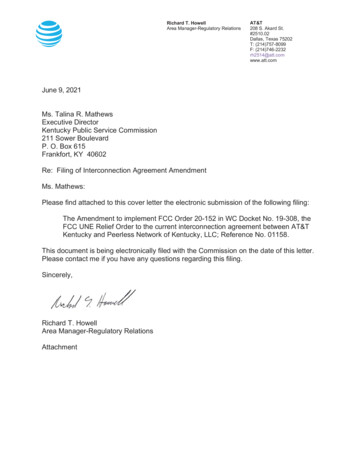
PLCS, LLCFlowstop BagsPLCS Flowstop Bags are designed with the bladder held inside a thin yetstrong synthetic fabric. This thin wall construction permits mains entrythrough a smaller tap hole than competitive brands.PLCS FLOWSTOP BAGPLCS FLOWSTOP BAGWITH RIGID SUPPORTWITH FLEXIBLE HOSETUBE, RUBBER BUNGAND GAUGE SETAND GAUGE SETx PLCS Flowstop Bags are barrel shaped to increase load on thex x x x x pipe wall to retain position and increase the surface seal area tominimize gas bypass.Bags are clamped to a semi-rigid inflation core to control entrydirection and prevent reversal in the main.Double end retention prevents bag loss during a sudden deflation.Standard sizes are available for all cast iron and steel mains from2"- 48".Special sizes are available for PE plastic pipe.Bags are rated at 1¼ psi for mains up to 12".In an "open-hole" Double Block and Bleed shutdown, PLCS FlowstopBags are recommended for use in pairs at each end of the shutdown.It is also possible to substitute one PLCS Flowstop Bag with a PLCSSensor Bag (see separate literature) at each end and be able tocontinuously record the upstream and downstream pressure duringthe shutdown.102 Gaither Drive, Unit 1, Mount Laurel, NJ 08054phone: (856) 722-1333 Ɣ fax: (856) 273-9723 Ɣ e-mail: info@plcsusa.com Ɣ web: www.plcsusa.com
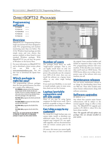
PLCS, LLCSensor BagsPLCS Sensor Bags continuously monitor pressure in the main duringshutdown, without the need for an additional tap.The bladder like the Flowstop Bag is held inside a synthetic fabricpermitting mains entry through a significantly smaller tap hole than anycompetitive product.x Gauges record the internal bagpressure and continuously recordthe upstream pressure in the mainthroughout a shutdown operationSENSOR TIPx The bags are barrel shaped toincrease load on the pipe wall toretain position and at the same timeincrease the surface seal area tominimize gas bypassx Sensor Bags are clamped to a semirigid inflation core to control entrydirection and prevent reversal in themain or bag loss during suddendeflationx Standard sizes are available for allcast iron and steel mains from 2"48"x Special sizes for PE plastic pipex Rated at 1¼ psi for mains up to 12"x Available with rigid inflation controltee and rubber entry stopperIn an "open-hole" Double Block and Bleed shutdown, Sensor Bags arerecommended for use in pairs at each end of the shutdown. By using 2 SensorBags not only is the internal bag pressure recorded, but it is possible to confirm azero pressure zone between the bags as well as separately monitor the upstreamand downstream mains pressures.* In a controlled gas environment102 Gaither Drive, Unit 1, Mount Laurel, NJ 08054phone: (856) 722-1333 Ɣ fax: (856) 273-9723 Ɣ e-mail: info@plcsusa.com Ɣ web: www.plcsusa.com
PLCS Flowstop Gas Bag Parts ListGas Main Shut DownComplete Assembly with Rigid Tube(C)MainSizeFlowstop BagPart #2”47-A0120 (C) or (F)3”47-A0121 (C) or (F)4”47-A0122 (C) or (F)*5”47-A0123 (C) or (F)6”47-A0124 (C) or (F)*7”47-A0125 (C) or (F)8”47-A0126 (C) or (F)*9”47-A0127 (C) or (F)10”47-A0128 (C) or (F)Flowstop Bag OnlyIncludes Brass Sweep, 0-15 psi InflationGauge, Mini Ball Valve, Bung, SchraderValveComplete Assembly with Flexible Tube(F)Includes Flexible Hose, 0-15 psi Inflation Gauge, MiniBall Valve, Schrader Valve*11” 47-A0128A (C) or (F)12”47-A0129 (C) or (F)*15”47-B0129 (C) or (F)16”47-B0130 (C) or (F)*18”47-A0184(C) or (F)20”47-B0131 (C) or (F)*24”47-B0132 (C) or (F)*26”47-B0135 (C) or (F)*30”47-B0133 (C) or (F)*36”47-B0134 (C) or (F) To order replacement Bag Only request part number only without the letter (C), or (F).To order complete bag assembly with brass stem include (C) to the part number.To order complete bag assembly with a flexible hose instead of the brass stem add (F) to the part number.NOTE – the flexible hose option is not available with a rubber bung.Complete includes brass insertion tube, inflation & deflation valve, bag inflation gauge with protective cover and rubber bung (“C” option ONLY).*Special order only, non -stock item.PLCS, LLC102 Gaither Drive, Unit 1, Mount Laurel, NJ 08054phone: (856) 722-1333 fax: (856) 273-9723 e-mail: info@plcsusa.com web: www.plcsusa.com
PLCS Sensor Gas Bag Parts ListGas Main Pressure Reading and Shutdown from One Hole.Complete Assembly with Rigid Tube(C)MainSizeSensor Bag PLCS Part #Sensor Bag OnlyIncludes Brass Sweep, 0-15 psiInflation Gauge, Mini Ball Valve,Bung, Sniffer Connector, SchraderValveComplete Assembly with Flexible Tube(F)Includes Flexible Hose, 0-15 psi InflationGauge, Mini Ball Valve, Sniffer Connection,Schrader ValveDoes not come with LP Gauge. Must Does not come with LP Gauge. Must orderorder separately (Part # 10-715).separately (Part # 10-715).2”47-A0682 (C) or �*36”47-A0683 (C) or (F)47-A0684 (C) or (F)47-A0685 (C) or (F)47-A0686 (C) or (F)47-A0687 (C) or (F)47-A0688 (C) or (F)47-A0689 (C) or (F)47-A0691 (C) or (F)47-A0693 (C) or (F)47-A0696 (C) or (F)47-A0698 (C) or (F)WIKA Low-Pressure MainMonitoring Gauge 0”-30” ¼” MNPT Center Backed Part#: 10-715A suitable low-pressure gauge or manometer must be installed for the bag system to operate as designed.To order replacement Bag Only request part number only without the letter (C) or (F).To order complete bag assembly with brass stem include (C) to the part number.To order complete bag assembly with a flexible hose instead of the brass stem add (F) to the part number.NOTE – the flexible hose option is not available with a rubber bung.Complete includes brass insertion tube, inflation & deflation valve, bag inflation gauge with protective cover and rubber bung (“C” option ONLY).*Special order only, non -stock item.PLCS, LLC102 Gaither Drive, Unit 1, Mount Laurel, NJ 08054phone: (856) 722-1333 fax: (856) 273-9723 e-mail: info@plcsusa.com web: www.plcsusa.com
WARNINGREAD BOTH SIDES BEFORE USETEST BAG BEFORE EACH USEDO NOT OVERINFLATE BAGS this may cause bagto burst.DO NOT use bags in gasoline, kerosene, oil, acid orsimilar substances.DO NOT use petroleum based solution to “soap test”the bag.DO NOT allow sparks, hot metal or welding slag tocome into contact with bag.DO NOT expose bag to temperatures in excess of150 F or lower than -20 F.DO NOT store, or leave bags in direct sunlight forextended periods.Store bags flat in a cool, dry area.DO NOT store anything on top of the bags.Inflate with an inert gas or clean dry air from an “oilfree” supply.Use with adequate ventilation.Additional information is available on our web site:PLCS, LLC 102 Gaither Drive, Unit 1 Mt. Laurel, New Jersey08054Tel: (856) 722-1333 Fax #: (856) 273-9723 info@plcsusa.comWeb Site: www.plcsusa.com
WARNINGREAD BOTH SIDES BEFORE USETEST BAG BEFORE EACH USETest: Inflate to ¼ of maximum bag pressurefor a minimum of 15 minutes.Replace bag and/or components if defective.Pressures shown below assume bags are on a rigid brass/copperstem and because of potential bag slippagedo not apply to bags on a flexible hose.Please contact PLCS for more information. MainDiameterSuggestedTap Hole SizeMax Bag InflationPressure (psi)Max MainsPressure 30”36”48”1”1”1”1 ¼”1 s follow OSHA and gas company safety practicesand standards when working on live mains.Remove all sharp edges from inside tap hole. Good stop-offs are usually achieved well belowmaximum inflation pressures.BAG SIZE
PLCSPhone: (856) 722-1333 Fax:(856) 273-9723 E-mail: info@plcsusa.com Web site: www.plcsusa.comndJuly 22 , 2014PLCS Sensor and Flowstop Bag & Component Replacement InstructionsFlowstop Bags:1.2.3.4.5.Flowstop Bags require schematic part #’s 1, 3, 4, 5, 6, 7, 9 and 10.Remove existing bag from the brass tube or flexible hose.Check ALL bag tube fittings and replace if worn or damaged, pay close scrutiny to the inflation gauge.Clean and re-tape all male threads with three wraps of Military Grade PTFE tape.If replacing the rubber bung push it onto the brass curved nipple with the narrow end of the taper pointing towards the bend (asshown).6. DO NOT OVER-TIGHTEN BRASS FITTINGS. Brass fittings are soft metal; over-tightening could crack fittings causingleakage.7. In a vice tighten together parts 5, 6, 7, and 9. Note: # 7 is set into the top outlet of the cross and # 9 is set into a side outlet.Remove fittings from the vice.8. Using “soft” jaws secure the brass nipple into the vice.9. Attach and tighten the Flowstop bag to the short leg with the curvature facing upwards (allows easy insertion into the main).DO NOT OVER TIGHTEN.10. Attach the completed top fittings to the opposite end of the brass nipple.11. Close valve and inflate bag with an inert gas or clean dry air from an OIL – FREE supply to 25% of maximum bagpressure indicated on bag tag. Monitor for pressure decay for a minimum of 15 minutes. DO NOT soap test bags witha petroleum based product.Bag tags shows bag Maximum Inflation Pressures when inserted in a main. When testing bags out of the main the bag isunsupported and MUST NOT be tested to a pressure greater than 25% of the maximum inflation pressures.Sensor Bags:1.2.3.4.5.6.7.8.9.10.12.11.12.Sensor Bags require schematic part #’s 1, 2, 3, 4, 5, 6, 7, 8, 9, and 10.Remove existing bag from the brass tube or flexible hose.Check ALL bag tube fittings and replace if worn or damaged, pay close scrutiny to the inflation gauge.Clean and re-tape all male threads with three wraps of Military Grade PTFE tape.If replacing the rubber bung push it onto the brass curved nipple with the narrow end of the taper pointing towards the bend (asshown).DO NOT OVER-TIGHTEN BRASS FITTINGS. Brass fittings are soft metal, over-tightening could crack fittings causingleakage.In a vice tighten together parts 5, 6, 7, 8 and 9 as shown with part # 8 at 90 to the cross. Remove fittings from the vice.Using “soft” jaws secure the brass nipple into the vice.Attach the Sensor bag hand -tight only onto the brass nipple short leg by inserting the white tube into and through the brassnipple.Position the pre-tightened fittings (5, 6, 7, 8, & 9) over the ⅛” white tube and hand-tighten. Moisten the leading edge of the ⅛”tube and carefully lower the sniffer connection over it and into the brass cross and tighten. Tighten the top fittings onto thebrass nipple. The ⅛” white tube is too long at this time but will be cut to length later.Tighten the bag with the curvature facing upwards (allows easy insertion into the main). DO NOT OVER TIGHTEN.Trim the white inner tube to length by pushing the white tube into the sniffer connector as far as it will go, hold the tube betweenyour thumb and finger as an indicator of its position then pull up on the tube. Using a sharp knife cut the ⅛” tube approximately¼” below finger and thumb. The tube is now long enough to prevent it sliding back below the o-ring in the sniffer connector butshort enough to allow the installation of a monometer gauge.Close valve and inflate bag with an inert gas or clean dry air from an OIL – FREE supply to 25% of maximum bag pressureindicated on bag tag. Monitor for pressure decay for a minimum of 15 minutes. DO NOT soap test bags with a petroleumbased product.Bag tags show bag Maximum Inflation Pressures when inserted in a main. When testing bags out of the main the bag isunsupported and MUST NOT be tested to a pressure greater than 25% of the maximum inflation pressures.
PLCS102 Gaither Drive, Unit 1 Mt. Laurel, NJ 08054August 10th, 2016Operating & Storage Procedures for PLCS Low-PressureFlowstop & Sensor Bags:Receipt:1.Check bag(s) for any damage that may have been caused during shipping. Report damage immediately to delivery carrier and PLCS.2.Inflate bag(s) to 25% of maximum pressure shown on bag label with an inert gas or clean dry air from an OIL-FREE supply. Monitor forany pressure loss for a minimum of 15 minutes. DO NOT soap test bags with a petroleum based product. If bag pressure cannot bemaintained contact PLCS immediately. No claims for malfunctioning product will be honored 30 days past shipping.Use & Storage:1.All bags have a manufactured date (MM-YY) stamped on the NPT hex brass fitting.2.Shelf Life: Shelf life is 36 months from manufactured date and prior to first use. If a bag is unused and properly inventoried it will be “fit for purpose” up to thirty six months after manufactured date. Used bags cannot be returned for credit as PLCS could not control the conditions under which they were used. Any bag older than thirty six months should not be used.3.Correct Storage of Gas Bags:a) Store in a cool, dry environment out of direct sunlight and not subject to excessive changes in temperature.b) Do not stack anything on top of bags during storage.c) Bags MUST be stored flat, NOT folded, wrinkled or rolled up.d) Rotate bag inventory – first in first out. Bags may be returned to PLCS for testing and/or component replacement. Pleasecontact PLCS for details and pricing.4.Prior to each use of the bag:a) Visually inspect bag and fittings for any damage and replace if necessary.b) Check bag by inflating to 25% of maximum bag pressure shown on bag label and monitor for any pressure decay for aminimum of 15 minutes. If a pressure drops, check all connections and re-tighten as necessary. DO NOT OVER INFLATEBAG AS THIS MAY CAUSE IT TO BURST. If any damage is observed, or the bag cannot retain pressure, discard the bag.c) Avoid contact with petroleum based products as these will have a detrimental effect on the life of the latex bladder. Any oilcontaminated bags should be removed and replaced with new bags.Operating Procedures: Use with adequate ventilation, wear protective clothing, gloves and safety glasses.Use breathable air when working in a gaseous environment.Read and follow directions on Bag Tag.Carefully insert bag through the tap hole into the main then slide the rubber bung down to create a good seal. If necessary, pack ductseal around each tap hole after bag is inserted and fully expanded to prevent gas vapors escaping into work area.Inflate bags with an inert gas or clean, dry air from an OIL-FREE supply.Always double bag and use vent pipes with flame traps between stop offs. Vents should extend at least 8 feet above ground level.DO NOT use bags in gasoline, kerosene, oil, acid or any similar substances.DO NOT use petroleum based solution to “soap” test bag.DO NOT allow sparks, hot metal or welding slag to come into contact with bags.REMOVE all sharp edges from inside and around tap hole to prevent damage to bags.DO NOT exceed maximum bag or indicated mains pressure as this may cause bag failure.DO NOT expose bags to temperatures in excess of 150ºF or lower than -20ºF.AFTER USE return bags to storage (see item 3 above for correct storage procedures).ALWAYS follow OSHA safe practices and gas company procedures when working on live gas.Please Note: These instructions are supplied as a guide and DO NOT replace your company policies or procedures. Always followyour company procedures and safety standards when working on live gas.Tel: 856-722-1333 Fax: 856)273-9723 Email: info@plcsusa.com Web site: www.plcsusa.com
PLCS, LLC 102 Gaither Drive, Unit 1, Mount Laurel, NJ 08054 phone: (856) 722-1333 fax: (856) 273-9723 e-mail: info@plcsusa.com web: www.plcsusa.com PLCS Sensor Gas Bag Parts List Gas Main Pressure Reading and Shutdown from One Hole. Main Size Sensor Bag PLCS Part # Sensor Bag Only Complete Assembly with Rigid Tube (C)