Transcription
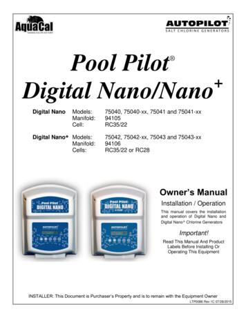
Pool Pilot Digital Nano/Nano Digital NanoModels:Manifold:Cell:75040, 75040-xx, 75041 and 75041-xx94105RC35/22Digital Nano Models:Manifold:Cells:75042, 75042-xx, 75043 and 75043-xx94106RC35/22 or RC28Owner’s ManualInstallation / OperationThis manual covers the installationand operation of Digital Nano andDigital Nano Chlorine GeneratorsImportant!Read This Manual And ProductLabels Before Installing OrOperating This EquipmentINSTALLER: This Document is Purchaser’s Property and is to remain with the Equipment OwnerLTP0086 Rev-1C 07/28/2015
iTABLE OF CONTENTSSECTION 1 -FACTORY CONTACT INFORMATION. 1SECTION 2 -SAFETY INFORMATION . 1SECTION 3 -OWNER QUICK START & RUN . 33.1 How Your Digital Nano/Nano Works . 33.2 Control Overview . 43.2.1 Up and Down Arrows . 43.2.2 The Boost Button . 43.2.3 Menu and Select Button . 43.2.4 Check System Light and Audio Alarm . 43.3 Normal Display. 53.4 Water Balance & Chemistry Recommendations . 5SECTION 4 - SPECIFICATION AND APPROVALS . 64.1 Specifications . 64.2 Manifold Pressure Drop Versus Flow . 64.3 Agency Approvals . 6SECTION 5 - FEATURES . 75.1 Patented Temperature Compensation . 75.2 Water Manifolds Assemblies - Available Options . 75.2.1 Automatic-Flow Bypass Manifold Assembly (#94105 and #94106) . 85.2.2 CoPilot Manifold Assembly . 8SECTION 6 - MAINTENANCE. 96.1 Fuse Location and Ratings . 96.2 Removing / Inspecting / Cleaning Tri-Sensor . 106.2.1 Tri-Sensor Assembly Overview . 106.2.2 Inspect Tri-Sensor . 106.2.3 Cleaning Tri-Sensor . 116.2.4 Test Tri-Sensor Flow Switch . 116.3 Servicing the Cell . 126.3.1 Removal . 126.3.2 Visual Inspection . 126.3.3 Manual Cleaning . 136.3.4 Installing . 136.4 Winterizing . 146.5 Spring Start-up . 14SECTION 7 - PROGRAMMING . 157.1 Control Panel . 157.1.1 Button Overview . 157.1.2 Menu Button . 157.1.3 Display Overview . 157.2 Menus . 167.3 Basic Operational Programming . 167.3.1 Adjusting the Chlorine Output % . 167.3.2 Boost or Super Boost . 177.3.3 Chlorine Mode . 177.3.4 Chlorine % Adjustment Procedure . 177.4 Test Pool Pilot (Diagnostic Menu) . 187.5 View Setup . 18
iiTABLE OF CONTENTS7.6 Review of Installer, Owner, & Maintenance Menu Programming . 197.6.1 Pool Volume . 197.6.2 Calibrating Salt . 197.6.3 Select Language . 197.6.4 Calibrating Temperature . 207.6.5 Select Units . 207.6.6 Temperature . 207.6.7 Set Reverse Time . 207.6.8 Program Cell’s self-cleaning cycle . 207.6.9 Force Reverse: . 217.6.10 Audio Alarm:. 21SECTION 8 - INSTALLATION . 228.1 Basic System Overview . 228.2 Before Installing . 238.3 Parts . 238.4 Installation Steps . 248.5 Plumbing Requirements. 248.5.1 Plumbing the Manifold Assembly . 248.6 Mounting the Digital Nano/Nano . 258.7 Electrical. 268.7.1 Electrical Connections. 268.7.2 AC Input Voltage . 268.7.3 Low Voltage Wiring . 268.7.4 Low-Voltage Cable Connections at Control Center . 278.7.5 Grounding and Bonding . 278.7.6 Connecting to an External Timer or Controller . 278.8 Preparing the Pool Water. 288.8.1 Steps to Prepare Water. 288.8.2 Calculating Pool Volume . 288.8.3 Adding Salt . 298.9 Programming at Installation . 30SECTION 9 -TROUBLESHOOTING. 31SECTION 10 - REFERENCE . 3610.1 Basic Water Chemistry . 3610.1.1 Chlorine . 3810.1.2 pH . 3810.1.3 Total Alkalinity . 3810.1.4 Calcium Hardness . 3810.1.5 Cyanuric Acid . 3810.2 Using the Saturation Index . 3910.3 Salt Addition Chart . 3910.4 Declaration of Conformity . 4110.5 FCC Compliance . 41
Page 1SECTION 1 - FACTORY CONTACT INFORMATIONIf you should need to call AquaCal AutoPilot, Inc. for questions, services, or parts, please have yourmodel and serial numbers available. Please also have the name of your installer and date of yourequipment’s installation. If you have questions, please refer to our web site for the latest manualrevisions, additional information, and helpful service advice.Webwww.AutoPilot.comPower Supply SerialPhone(727) 823-56428-5 pm, Est., M-FCell SerialFax(727) 821-7471Tri-Sensor SerialAddressAquaCal AutoPilot, Inc.th2737 24 Street NorthSt. Petersburg, Florida 33713USAInstallerInstall DateSECTION 2 - SAFETY INFORMATIONFor personal safety, and to avoid damage to equipment, follow all safety instructions displayed on theequipment and within this manual. Repair and service of your Digital Nano/Nano must be performedby qualified service personnel. Should you suspect your chlorine generator is not performing properly,refer to the section in this manual entitled: "Troubleshooting," to determine if a call for service isrequired. Warranties will be voided if the Digital Nano/Nano has been improperly installed. Failures toproperly operate, maintain, or repair the Digital Nano/Nano will void factory warranty.Throughout this manual safety signals are placed where particular attention is required. Please note"WARNING" signals relate to personal safety, while "CAUTION” signals promote avoiding damage toequipment.Follow all state, provincial and NEC (National Electrical Codes) and applicable CEC (CanadianElectrical Codes) unless local guidelines supersede. When installing and using your DigitalNano/Nano , basic safety precautions must always be followed, including the following:WARNING - Failure to heed the following may result in injury or death. RISK OF ELECTRICAL SHOCK - Disconnect all AC power when installing or servicingthis system. Follow all state, local, and National Electrical Code(s) (provincial andCanadian Electrical Code(s) if applicable). Use copper conductors only. RISK OF ELECTRICAL SHOCK - Digital Nano/Nano contains no Owner-repairablecomponents. Repairs must not be attempted by untrained and/or unqualified individuals.If service is deemed necessary, contact installing dealer or AquaCal AutoPilot CustomerSupport. RISK OF ELECTRICAL SHOCK - A bonding lug has been provided on the outside of theDigital Nano/Nano . This lug permits the connection of a No. 8 AWG (8.4 mm2) solidcopper-bonding conductor (No. 6 AWG in Canada). Make this connection between theDigital Nano/Nano and all other electrical equipment and exposed metal within 5-feet(1.5 m) of the Digital Nano/Nano . All field-installed metal components (such as rails,ladders, drains, etc.) within 10-feet of the pool, spa, or hot tub, must be bonded to the
Page 2 equipment grounding bus using copper conductors not smaller than No. 8 AWG(8.4mm2) (No. 6 AWG in Canada).Maintain water chemistry in accordance withmanufacturer’s instructions.RISK OF ELECTRICAL SHOCK - Digital Nano/Nano configured to 115 Vac must beinstalled at least 10 feet (3 m) from the pool or spa wall. Digital Nano/Nano configuredto 230 Vac must be installed at least 5 feet (1.5m) from the pool or spa wall.RISK OF ELECTRICAL SHOCK - A disconnect device incorporated into the fixed wiringmust be included in the supply circuit (such as a time clock, relay, or circuit breaker).RISK OF ELECTRICAL SHOCK - Connect only to a branch circuit protected by aground-fault circuit-interrupter (GFCI). Contact a qualified electrician if you cannot verifythat the circuit is protected by a GFCI.RISK OF ELECTRICAL SHOCK - Digital Nano/Nano must be connected only to asupply circuit that is protected by a ground-fault circuit-interrupter (GFCI). The GFCImust be tested on a routine basis. To test, push the GFCI test button. Power should beinterrupted. Push the reset button. Power should be restored. If the GFCI fails to operatein this manner, it is defective.RISK OF ELECTRICAL SHOCK - If the ground-fault circuit-interrupter (GFCI) interruptspower to the equipment without the test button being pushed, a ground current is flowingwith a possibility of an electrical shock. Do not use equipment. Disconnect theequipment and have the problem corrected by a qualified service representative beforeusing.CHEMICAL HAZARD - To avoid damaging splashes, always add acid to water, neverwater to acid. Wear safety glasses and use other appropriate personal protectionequipment.CHEMICAL HAZARD - Always follow the instructions on the manufacturer's labelwhenever handling or using chemicals.CHEMICAL HAZARD – Heavy pool (or spa) usage and higher temperatures may requirea higher chlorine output in order to maintain proper free available chlorine residuals.WATER CHEMISTRY SAFETY - Improper water chemistry can present a serious healthhazard. The proper residual chlorine level and water chemistry must be maintained. Theaddition of certain pool maintenance chemicals can reduce the effectiveness of chlorine.Maintain Pool / Spa water per standards detailed later in this manual.COMBUSTIBLE HAZARD – The AquaCal AutoPilot Digital Nano/Nano is equipped withan electronic flow switch that automatically turns the unit off in the event of a “low waterflow” situation. Do not tamper in any way with this safety feature.PERSONAL SAFETY HAZARD – To reduce the risk of injury, do not permit children tooperate this device.RISK OF CHILD DROWNING OR INJURY - Children must be closely supervised at alltimes around pool or spa equipment.CAUTION - Failure to heed the following may result in equipment damage.The AquaCal AutoPilot Digital Nano/Nano must be installed and operated as specified.Failure to do so will void the equipment warranty.To permit proper air circulation, the Digital Nano/Nano must be mounted at least 1-foot(30 cm) above ground level or any other cooling obstruction.Special measures are required in the event of freezing conditions. Your DigitalNano/Nano may be damaged if measures are not taken in advance of freezing
Page 3 conditions. Equipment damage due to freezing conditions is NOT covered under theequipment warranty.Do not use a pool cleaner or vacuum head with wheels, as wheels can leave trackmarks on newly-plastered pools. Do not allow Granular salt to pile up in one location,without brushing, as staining may occur.Excessively high chlorine levels can cause premature cell failure and corrosion damageto pool fixtures and equipment.For maximum cell life, maintain water in a balanced condition. Water maintained in ascaling condition will shorten cell life and may render the Digital Nano/Nano inoperative. Damage and/or service calls, caused by improper water balance, will NOTbe covered under the equipment warranty.Scraping or scratching the titanium blade’s edge or surface will damage the bladecatalyst coating and cause premature failure of the cell. warranty will be voided. Neveruse any sharp or metallic objects to remove scale.Reduced polarity reversing cycle times will reduce cell life, and should only be used dueto uncontrollable scale formation on the cell. ALWAYS test and adjust water balance,before attempting scale control via shortening reverse period.The Tri-Sensor should not be pulled out at an angle, or the flow paddle or flow post maybe damaged.SAVE THESE INSTRUCTIONSSECTION 3 - OWNER QUICK START & RUN1) Balance the water chemistry according to the water chemistry parameters on page 5 and saltrecommendations on page 29. The Digital Nano/Nano may be started immediately. The saltreading, however, may initially be inaccurate until the circulation pump has been run for 24hours to fully dissolve newly added salt.2) Use the “UP” and “DOWN” arrow buttons to set the chlorine percentage to 50%.3) During the first two weeks, test the water chemistry parameters every 3-4 days. Adjust chlorinepercentage as needed.4) Once ideal chlorine percentage has been determined, follow normal maintenance procedures.3.1 HOW YOUR DIGITAL NANO/NANO WORKSThe Digital Nano/Nano is designed to handle the purification needs of residential swimming pools andspas. The amount of chlorine required for proper sanitization will vary based on the pool size andvarious factors such as water temperature, bather load, exposure to direct sunlight, and special waterfeatures.The system requires a low concentration of dissolved salt (sodium chloride) in the water. The saltconcentration level is normally maintained below the taste threshold. The Digital Nano/Nano automatically converts the salt into chlorine, which your pool/spa requires to remain sanitized and algaefree. The chlorine reverts back to salt after treating the water. Since the salt is constantly recycled,there is minimal loss during a swimming season. However, salt can be lost due to filter backwashing,rain water overflow, leaks, or bather splashing/carry out. but not through evaporation.The water circulation pump must be operating for your Digital Nano/Nano to produce chlorine, so runtime is one of several key components to maintaining the proper sanitizer levels. Most installationsrequire a minimum of eight (8) hours-per-day pump run time to properly filter and sanitize the water.
Page 43.2 CONTROL OVERVIEWThe following is a brief explanation of owner or operator control options. For full features of the OwnerOptions Menu, please see page 19. The MENU button is pressed to obtain access to the OwnerOptions Menu.Please Note: This section assumes the installer has already programmed the system forspecific site parameters, has established proper water balance, and has pretreated water to 1 3 ppm (mg/L) chlorine.Attention Owner: Should Centigrade vs. Fahrenheit, choice of language, or other owner optionsrequire modification, please refer to the programming information located on page 19.See: Menu Button and Owner Options.3.2.1 Up and Down ArrowsUse the UP and DOWN arrows to control the chlorine output level, then press the SELECTbutton to save the value chosen. With a properly prepared pool, the recommended startingoutput level is 50%.Upon initial start-up, check sanitizer every 3-4 days and make small output level adjustments asnecessary to maintain 1-3 ppm (mg/L) free chlorine levels. Keep in mind, your DigitalNano/Nano does not directly measure or regulate the sanitizer levels in your pool. Rather, theowner / operator will need to periodically test the water to determine the current chlorine level,and adjust the output setting as needed.After the chlorine output level is “tuned in,” the unit will automatically make fine outputadjustments as the water temperature fluctuates. This temperature compensation feature willadjust output depending on water temperature. See page 7 for more information concerning thepatented temperature compensation feature.Please Note: The optimum output setting will vary based upon pool size, location, exposure tosunlight, number of users, vegetation around the pool, water balance practices, and pump runtime. Your installer should have already taken these factors into consideration when performinginstallation programming. Therefore, your adjustments, at this point, should be relatively minor.3.2.2 The Boost ButtonThe BOOST button increases output to 100%. Use this feature when a heavier than normalbather load is anticipated.Press BOOST once . 24 Hour BoostPress and hold BOOST for 8 seconds 72 Hour BoostPress BOOST a second time . Deactivate Boost3.2.3 Menu and Select Button This allows access to the “Test,” “Setup,” “Owner Option,” “Maintenance,” and “Installer” menus.The “SELECT” button allows the operator to choose program menu options. The owner /operator should not normally need to access these features on a regular basis.Consult “Programming” section, or contact factory customer support for additional information.3.2.4 Check System Light and Audio AlarmThe CHECK SYSTEM light will flash to warn the unit may need attention. A warning message willalso be displayed. If enabled, an audio alarm* may also be heard when the system light is flashing.Unless deemed a normal condition, per below, see troubleshooting section. Flashes red when pump is off / water flow is insufficient. (It is normal for the light to flash ifthe circulation pump is off) Flashes when salt is low
Page 5 Flashes when water temperature exceeds 125 F, or drops below 10 FNote: When enabled, an audio alarm will sound due to any of the above three (3) conditions. Ifwater flow ceases (or falls below minimum acceptable levels) the alarm will automatically silenceafter 10 minutes. To enable or disable audio alarm, see “Audio Alarm” in programming instructions.3.3 NORMAL DISPLAYChlorine Output level . in 1% increments, from 0% to 100%Water Temperature . in Fahrenheit or CelsiusCell Status. ON or OFFCheck System Light . OFF when operating normallyCheck System Light . Normally blinking when circulation pump is off and supply power tothe controller remains on.3.4 WATER BALANCE & CHEMISTRY RECOMMENDATIONSProper water balance is critical to the operation of your Digital Nano/Nano .Conditions such as high pH levels, low Cyanuric acid (stabilizer) levels, or other factors causingunbalanced water, will mask the sanitizer production of your Digital Nano/Nano .Please note the following recommended water chemistry parameters are for residential pool/spaapplications only. Follow local regulatory guidelines for any commercial pool applications.POOLPARAMETERFree ChlorineCombined ChlorinepHTotal AlkalinityCalcium HardnessSaltSPAUNITSMINIDEALMAXMINIDEALMAXppm (mg/L)ppm (mg/L)1.00.07.26015020002.0 - 4.00.07.2 -7.880 - 100200 - 4002500 - 350050.27.81801000**2.00.07.26010020003.0 - 4.00.07.2 -7.880 - 100150 - 2502500 - 3500100.57.81801000**030 - 50***030 - 50***ppm (mg/L)ppm (mg/L)ppm (mg/L)Cyanuric Acid (stabilizer) ppm (mg/L)Table 1**Typically 6000 ppm (mg/L) or less is recommended; unit can operate with levels as high as35,000 ppm (mg/L).*** This is dictated by state or local codes but is typically 100 ppm (mg/L).See “Basic Water Chemistry” on page 36 and “Using the Saturation Index” on page 39 for furtherinformation concerning pool/spa water chemistry maintenance requirements. Or refer to theTroubleshooting section in the back of this manual.
Page 6SECTION 4 - SPECIFICATION AND APPROVALS4.1 SPECIFICATIONSSPECIFICATIONInput Power75040, 75040-XX 75041, 75041-XX110-120 Vac2.0 A220-240 Vac1.0 A75042, 75042-XX75043, 75043-XX110-120 Vac2.0 A220-240 Vac1.0 AMaximum Chlorine OutputRC35/220.8 lb. /day (15.11 g/hr.)0.8 lb. /day (15.1 g/hr.))Maximum Chlorine OutputRC28not applicable1.06 lb. /day (20.0 g/hr.)Minimum Flow Ratefor 941xx15 gpm (76 L/min)Minimum Flow Rate forCo-Pilot Ozone25 gpm (95 L/min)Maximum Flow Rate100 gpm (379 L/min)Maximum OperatingPressure85 psiTable 24.2 MANIFOLD PRESSURE DROP VERSUS FLOWThe following chart shows pressure drops versus flow for all Digital Nano/Nano manifolds. Theoptional CoPilot Ozone manifold is also listed.Table 34.3 AGENCY APPROVALSTested to conform to the following specifications:APPROVALDESCRIPTIONUL1081Standard for Safety for Swimming Pool Pumps, Filters, and Chlorinators.CAN / CSA-E60335-1Safety of Household and Similar Electrical Appliances.
Page 7SECTION 5 - FEATURES Patented temperature compensation for chlorine output control.Programmable microprocessor control.Multi-language digital display (English, Spanish, French and either Italian or Czech).Digitally controlled power to the cell.Tri-Sensor circuitry to monitor water flow, water temperature, and salt level. Calculates andprovides recommended salt addition amounts required to maintain the recommended 3000 ppm(mg/L) salt concentration level.5.1 PATENTED TEMPERATURE COMPENSATIONWARNING- Failure to heed the following may result in permanent injury or death.Pool or Spa water temperature should not exceed 104 F (40 C).The
Pool Pilot Digital Nano/Nano Digital Nano Models: 75040, 75040-xx, 75041 and 75041-xx Manifold: 94105 Cell: RC35/22 Digital Nano Models: 75042, 75042-xx, 75043 and 75043-xx Manifold: 94106 Cells: RC35/22 or RC28 Owner's Manual Installation / Operation This manual covers the installation