Transcription
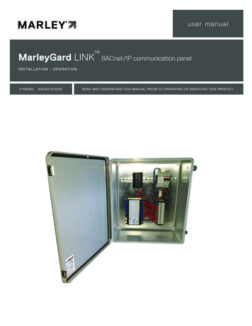
user manualMarleyGard LINK BACnet/IP communication panelI N STA L L AT I O N - O P E R AT I O NZ1126362ISSUED 9/2020READ AND UNDERSTAND THIS MANUAL PRIOR TO OPERATING OR SERVICING THIS PRODUCT.
contentsNoteThis manual contains vital information for the proper installationand operation of the MarleyGard LINK. Carefully read the manualbefore installation or operation and follow all instructions. Save thismanual for future reference.Description.4System Diagram.5I/O Module - Panel Specifications.5Quick Start Guide.6Input Assignment Table.7Setup Programming.7Web Page Configuration.92
introductionThese instructions are intended to assure that field connections are completedproperly and the control system operates for the maximum time possible. Sinceproduct warranty may depend on your actions, please read these instructionsthoroughly prior to operation.If you have questions about the operation and/or maintenance of this controlsystem and you do not find the answers in this manual, please contact yourMarley sales representative.WarningHazard of electrical shock or burn. Be sure to turn off power to thepanel before servicing. If working on equipment out of site of paneldisconnect, lockout using standard lockout procedure.Safety FirstThe MarleyGard LINK uses UL listed components installed in accordancewith the National Electric Code. The location of the cooling tower and fieldinstallation of the control system can affect the safety of those responsiblefor installing, operating or maintaining the tower and controls. However,since SPX Cooling Technologies does not control the tower location, or fieldinstallation, we cannot be responsible for addressing safety issues that areaffected by these items.WarningThe following safety issues should be addressed by those responsiblefor installation, maintenance or repair of the tower and controls: Access to and from the control panel (including the customer suppliedmain disconnect/branch circuit protection) Proper grounding of electrical control circuits Sizing and protection of branch circuits feeding the control panel Qualification of persons who will install, maintain and service the electrical equipmentThese are only some of the safety issues that may arise in the design andinstallation process. Consult a safety engineer for additional guidance.Other safety issues are addressed in literature supplied with your tower. Youshould closely review the literature prior to installing, maintaining or repairingyour tower.3
descriptionEnclosure HeaterPower SupplyMain CircuitBreakerSurge ProtectorUser TerminalStripI/O ModuleThe MarleyGard LINK panel, in conjunction with a Marley cooling towercontrol panel provides a means for a BACnet/IP system to capture statuspoints and analog readings from a Marley cooling tower.Incoming power:120 VAC, 2A, 50/60 HzMain circuit breaker: 6AAmbient temperature: -10 F (-23 C) to 110 F (43 C)Enclosure:NEMA 4X (IP56) outdoor fiberglass18"W x 20"H x 9"DSurge protection:YesEnclosure heater:YesI/O module terminals: RemovableUser terminal strip:YesStandards:UL/CUL 508A AssemblyModule: BACnet/IP4
descriptionI/O ModuleOutput pointsnot usedInput points fromMarley cooling towercontrol panelRJ45 BACnet/IPout to BMS24 VDC powerinputRJ45 input from VFDethernet BACnet/IPadapterNote: CoolBoost fluid cooler control panels require two I/O modulesSystem DiagramComponent Status PointsVibration SwitchMarley Cooling Tower CellOil LevelSwitchMarley Control PanelMarleyGard LINK PanelBMS SystemBACnet/IPCableFan MotorStatus Pointsand PowerWater LevelControlNote: All Marley VFDs with a LINK interface have an Ethernetmodule with an RJ45 jack for connecting the VFD to the LINKcontrol panel.Basin Heater5
installationThe communications module is BACnet compliant and programmed by Marleyfor job specific configuration. The LINK panel is available as an “add on box”integrated into a Marley cooling tower control panel system.Each LINK panel is serialized with a cooling tower order number located onthe inside door of the control panel. Refer to this number when addressingquestions or support with SPX Cooling Technologies.The MarleyGard LINK panel is compatible with Marley control panels: AIO control panel SPPC control panel CoolBoost control panel ABH control panelQuick Start Guide Mount LINK enclosure adjacent to a Marley control panel. I dentify job site points to monitor in the Marley control panel. Run 120VAC power wiring from the Marley control panel to the LINKpanel in separate conduit. Run conduit for status wires from the control panel to BACnet panel inseparate conduit. Seal conduit runs with expanding foam or silicone making a vapor barrierto prevent condensation. Spring clamp terminal block instructions: Strip field wire insulation back7/16". Insert small flat blade screw driver into the square hole then pushdownwards to release the internal wire clamp, while holding downwardinsert the field wiring then release the driver.6
installationSetup Programming The BAScontrol22C module used in the LINK control panel is preprogrammed according to cooling tower components status pointsselected for a project. Actual monitoring points may vary by projectrequirements for BMS monitoring. I P address, setup and descriptions may be changed in the field using aPC and RJ45 ethernet patch cable, software is not required. The defaultIP address is 192.168.92.68. For additional support see I/O module manufacturer's websitewww.ccontrols.com
8VIB LVL XMTRVIB LVL XMTROIL LVL ALMWATER LVL CWBWATER TEMP CWBWATER HIGH ALMWATER MAKEUP ONWATER LOW ALMBASIN HEATER ONBASIN HEATER FAILSPARESPRAY PUMP 1 ONSPRAY PUMP 1 TRIPSPRAY PUMP 2 ONSPRAY PUMP 2 TRIPSPRAY PUMP SAFETY TRIPDAMPER 1 OPENDAMPER 1 OPEN END SWDAMPER 1 CLOSED END SW Binary Input Damper 1 (fluid cooler - closed end switch is closed)DAMPER 2 OPENDAMPER 2 OPEN END SWDAMPER 2 CLOSED END SW Binary Input Damper 2 (fluid cooler - closed end switch is closedSPARE881076543912910111212345678Marley Field devices685B, 440640BABH with 4-20mA Temp cardDL10, DL24no-units N/Ano-units CoolBoost damper 2 closedno-units CoolBoost damper 2 openno-units CoolBoost damper 2 contactor energizedno-units CoolBoost damper 1 closedno-units CoolBoost damper 1 openno-units CoolBoost damper 1 contactor energizedno-units CoolBoost spray pump safety shutdownno-units CoolBoost spray pump 2no-units CoolBoost spray pump 2no-units CoolBoost spray pump 1no-units CoolBoost spray pump 1no-units N/Ano-units ABHno-units ABHno-units LLC LAno-units LLC MUno-units LLC HAmAmAno-units LU10mAmAno-units 685B, 440no-units 685A, 685B, 686B, 5550, 440UnitsXXXXXXXXXXXXXXXXXXXXXXXXXUI1 UI2 UI3 UI4 UI5 UI6 UI7 UI8 BI1 BI2 BI3 BI4Note: Data points shown are pre-programmed into the module but may not all be available depending on type and number of field devicesField devices for binary inputs use a normally open contact unless otherwise notedBinary Input Spare Input (binary)Binary Input Damper 2 (fluid cooler - open end switch is closed)Binary Input Damper 2 (fluid cooler - contactor is energized)Binary Input Damper 1 (fluid cooler - open end switch is closed)Binary Input Damper 1 (fluid cooler - contactor is energized)Binary Input Spray pump (fluid cooler - low water or freezing water safety trip)Binary Input Spray pump 2 TRIP (fluid cooler - motor over load)Binary Input Spray pump 2 ON (fluid cooler - contactor is energized)Binary Input Spray pump 1 TRIP (fluid cooler - motor over load)Binary Input Spray pump 1 ON (fluid cooler - contactor is energized)Binary Input Spare Input (binary)Binary Input Basin heater failed (heater is not drawing current)Binary Input Basin heater ON (cooling tower - heater drawing current)Binary Input Water level low (cooling tower CWB)Binary Input Water makeup solenoid valve open (cooling tower CWB)Binary Input Water level high (cooling tower CWB)Analog Input Water temperature transmitter (cooling tower CWB - loop powered by panel)Analog Input Water Level transmitter (cooling tower CWB - loop powered by panel)Binary Input Oil level (cooling tower - low oil in gearbox)Analog Input Vibration level transmitter (cooling tower - loop powered by switch)Analog Input Vibration level transmitter (cooling tower - loop powered by panel)Binary Input Vibration switch alarm (cooing tower notification - increasing vibration)Binary Input Vibration switch (cooling tower shutdown - high vibration)VIB SW ALMObject DescriptionVIB SW TRIPObject Type11Object Name12ObjectInstanceTypical Input Assignment TableModule 2CoolBoostControl PanelModule 1AIOSPPCABHCoolBoostControl Panelinstallation
installationWeb Page Configuration — Main Page and System he Model BAScontrol22C I/O user manual is included with the MarleyGardTLink control panel and is also available at www.ccontrols.comAccess to the web pages is intended for the installer or skilled technicians. Inorder to access any of the web pages authentication is required. The defaultIP address is 192.168.92.68 and the default User Name and Password isadmin/admin. Once on the main page, the System Configuration button canbe clicked.The main web page provides an overview of all real points plus access to otherweb pages. To configure a point, click on the point and a configuration page willappear. To observe the updated data for each point, click Auto Refresh buttonto ON. Point values can be temporarily forced by checking the box adjacent tothe point and entering a value into the point’s text box (make sure Auto Refreshbutton is OFF). The value will remain forced until the box is unchecked or theunit power cycled. Care must be exercised when forcing values into points.The IP settings can be changedto the desired values. EitherDHCP or a static IP addresscan be selected. If a static address is desired, enter the valuealong with the network maskand gateway address. If domainaddress is required, enter in thePrimary and Secondary DNSaddresses.BACnet device data must beentered when using BACnet.Make sure the Device Instance and Device Object Name are both uniqueover the complete BACnet Internetwork.9
MarleyGard LINKU S E R M A N UA LSPX COOLING TECHNOLOGIES, INC.7401 WEST 129 STREETZ1126362 ISSUED 9/2020OVERLAND PARK, KS 66213 USA 2020 SPX COOLING TECHNOLOGIES. ALL RIGHTS RESERVED913 664 7400 spxcooling@spx.comIn the interest of technological progress, all products are subject to designspxcooling.comand/or material change without notice.
points and analog readings from a Marley cooling tower. 5 Vibration Switch Marley Cooling Tower Cell Component Status Points Marley Control Panel MarleyGard LINK Panel BMS System Oil Level Switch Water Level . USER MANUAL SPX COOLING TECHNOLOGIES, INC. 7401 WEST 129 STREET OVERLAND PARK, KS 66213 USA 913 664 7400 spxcooling@spx.com .

