Transcription
Smart Series SSH-10-21, SSH-10-22,SHA-10-21, SHA-10-22 (AUSTRALIA),ESH-10-21, ESH-10-22 (EUROPE)Microprocessor-BasedSingle ZoneTemperature Control UnitWith Digital DisplayUser’s ManualD-M-E CompanyEE-000122-2006 REV: BD-M-E SSH, SHA, & ESH User’s ManualPage 1
Copyright D-M-E Company LLC 2010. All rights reserved.D-M-E Company products are covered by USA and foreign patents, trademarks and copyrightsissued and pending. Information in this publication supersedes that in all previously publishedmaterial. Specifications and any changes are reserved.Printed in the United States of AmericaD-M-E Company LLC29111 Stephenson HighwayMadison Heights, MI 48071 USAD-M-E Company and D-M-E are registered trademarks of D-M-E Company LLC.WARRANTYD-M-E Company warrants that this product will be free from defects in materials and workmanshipfor a period of three (3) years from the date of shipment. If any such product proves defectiveduring this warranty period, D-M-E Company, at its option, either will repair the defective productwithout charge for parts and labor, or will provide a replacement in exchange for the defectiveproduct.This warranty shall not apply to any defect, failure or damage caused by improper use or improperor inadequate maintenance and care. D-M-E Company shall not be obligated to furnish serviceunder this warranty a) to repair damage resulting from attempts by personnel other than D-M-ECompany representatives to repair or service the product; b) to repair damage resulting fromimproper use or connection to incompatible equipment; or c) to service a product that has beenmodified or integrated with other products when the effect of such modification or integrationincreases the time or difficulty of servicing the product.This warranty excludes replacement of Fuses, Triac, Calibration, and damage to theproduct from the use of improper styles of fuses. (Use only ABC type replacement F1 & F2Load Fuses) The maximum allowable Load Fuse rating is 10 amps. Lower ratings may beused for improved protection.SAFETYD-M-E Company products have been designed to be safe and simple to operate. As with anyelectronic equipment, you must observe standard safety procedures to protect both yourself andthe equipment.To Prevent Injuries: To avoid electrical shock or fire hazard, do not apply voltage to a terminal that exceeds therange specified for that terminal. To avoid mechanical injury, electrical shock or fire hazard, do not operate this product withcovers or panels removed. To avoid electrical shock or fire hazard, do not operate this product when wet. To avoid injury or fire hazard, do not operate this product in an explosive atmosphere.To Prevent Product Damage: Do not operate this product from a power source that applies more than the voltage specified.EE-000122-2006 REV: BD-M-E SSH, SHA, & ESH User’s ManualPage 2
D-M-E StandardSmart Series Microprocessor-Based Single ZoneTemperature Control Unit With Digital DisplaySSH-10-21, SSH-10-22,SHA-10-21, SHA-10-22 (AUSTRALIA),ESH-10-21, ESH-10-22 (EUROPE) GENERAL DESCRIPTION The Smart Series SSH, SHA, & ESH units are userfriendly temperature controllers of world-class caliber.They are based on one of the most widely usedcontrollers in the hot runner control industry.It has a large process temperature display, and itincorporates a 3-digit pushwheel for entering processtemperature setpoints.The illuminated display shows process temperature inAuto, and Manual modes.Diagnostic fault codes for open (“OPE”), reversed(“bAC”), or shorted (“SHO”) thermocouples are displayeddigitally. The module automatically inhibits output powerto the heater load in Auto mode until such faults arecorrected, unless the new “Automatic Bumpless Transfer”option is enabled.The units LED display indicators (located at the top left ofeach digit) show the mode of operation. The power toheater “load” LED doubles as a Smart Start indicator byblinking during Smart Start. Five separate color-codedLED's located under the display indicate temperaturedeviation and over/under temperature conditions at aglance.simulate manual mode using the average percent powerlearned during normal Auto operation.Manual Mode: For no thermocouple, or a thermocouplefailure, open loop percent output power is used.In Manual mode, the microprocessor maintains a powerlevel using an open loop power control method. Thisenables the user to continue production, and overridethermocouple faults until the problem has been resolved.Manual mode overrides thermocouple break protection,shorted thermocouple protection, reversed thermocoupleprotection, and any other normal automatic modes.FEATURES OPERATIONAuto Mode: The microprocessor maintains temperatureusing a proprietary closed loop control method. istics to make accurate adjustments and correctfor errors."Fuzzy logic" is used to minimize overshoot of setpoint onstart-ups, and to prevent over and undershoots whenchanging setpoints.The SSH, SHA, & ESH units can also display theaverage percent output power when running in Automode. (“% Auto” setting)Smart Start : Smart Start is automatic on start-up inAuto mode if the process temperature is below 212 F(100 C), and provides a linear power output ramp toensure safe heater dry out.Smart Start is completed after four minutes and thirtyseconds has elapsed, or when process temperatureexceeds the lesser of either the setpoint or 212 F (100 C)in Auto mode.Input Fault: Thermocouple break protection, andreversed thermocouple protection, override Smart Start when in Auto mode. (Output power is inhibited)Shorted thermocouple protection, thermocouple breakprotection, and reversed thermocouple protection, inhibitoutput power in normal Auto mode operation.If a thermocouple fault occurs when the “AutomaticBumpless Transfer” feature is ON (after operating atsetpoint temperature for 10 Minutes), the unit willEE-000122-2006 REV: B Fully self-tuning, fuzzy logic, microprocessor-basedcontrol.Selective Cycle and Smart Start to prolong heaterlife.Zero crossing triac triggering for minimum RadioFrequency Interference. (RFI)Process temperature display operational even inManual mode as long as the thermocouple (T/C) isintact.Automatic T/C fault protection and cold junctioncompensation.High impedance potentiometric input allows for longdistance T/C wiring.100% solid-state circuitry, no mechanical relays.Completely self contained, no external outputdevices or power supplies required.Fast acting heater load fuses are provided on bothsides of the AC line. (Except SHA)Electrically isolated, and grounded front panel foroperator safety. F/ C configurable.J-type, or K-type thermocouple configurable.New Lights Out feature can be enabled to shut offthe digital LED display during stable Auto control.Adjustable response time to shorted thermocouplefaults.NOTE: The SSH, SHA and the ESH units have a fewfunctional differences. The SHA has no fuse protection on the Neutral ACpower input line.The ESH/SHA operates in degrees Celsius and theSSH operates in degrees Fahrenheit, however eachunit can be re-configured to the other mode ofoperation. (See “Temperature Mode” on page 6)The ESH connector on the back panel is wireddifferently from the SSH/SHA.(See “Wiring The Load” on page 6)D-M-E SSH, SHA, & ESH User’s ManualPage 3
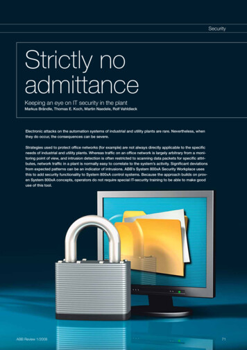
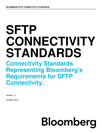
Figure 1 - DisplayPERFORMANCE SPECIFICATIONSAuto and Manual Control Modes: Selective Cycle: highspeed time proportioning.Temperature Range: Ambient to 999 F (537 C) with Jtype, and K-type thermocouples.Control Accuracy: /-1 F (0.5 C), dependent on thetotal thermal system.Temperature Stability: /-0.5% of full scale over theambient range of 32 to 120 F. (0 to 50 C)Calibration Accuracy: Better than 0.2% of full scale.Power Response Time: Less than 0.13 seconds.Reset: Automatically corrects reset to no more than /-1 F (1 C) at all settings.Manual Control: Adjustable from 0-99%. Maintainsoutput power to within 1% of setting.Diagnostics Indicators: LED’s and 3-digit, 7-segmentdisplay.Smart Start (SS): Linear power output ramp from aninitial temperature ( 212 F in Auto mode) to ensur e safeheater dry out.SS Duration: 4-1/2 minutes.SS Override Temperature: 212 F (100 C) Auto modeonly.Operational Mode Priority: Smart Start precedes Auto mode if processtemperature is 212 F. Thermocouple (T/C) break, or reversed T/Coverrides Auto mode Smart Start, and normal Automode. Shorted T/C overrides normal Auto mode. Manual mode overrides T/C break, T/C open, andreversed T/C. The output is inhibited during all T/C fault conditionsin Auto mode unless Automatic Bumpless Transferis enabled.DIAGNOSTICS ANDCODES (See figure 1)OTHERDISPLAYThe SSH , SHA, & ESH diagnostics automatically alertthe user to a fault condition. Shorted thermocouple indicated by flashing SHO. TroubleshootingCheck for damage to the thermocouple leadwire. Also check for bare, twisted or pinchedleads, open load fuse (F2, and/or F1), orexcessive distance between the heater andthermocouple.EE-000122-2006 REV: B Open thermocouple indicated by flashing OPE. TroubleshootingCheck the thermocouple connections and wiresfor broken leads, check for damage to thesensor, or check for open fusible link resistor(R4, see figure 8)Reversed thermocouple indicated by flashing bAC. TroubleshootingCheck thermocouple wiring for reversed leads.Over/Under temperature. The red deviation LED onthe left, flashes when the process temperature isbelow setpoint by 40 F or more. The red deviationLED on the right flashes when the process is abovesetpoint by 40 F or more. TroubleshootingUnder temperature;open heater, low line voltage, T/C problem,open load fuse (F2, and/or F1).Over temperature;output failure, shorted triac, interacting zones,heater shorted to ground.A flashing Loc is an indication that the Smart StartOverride Disable option is ON, and that the unit is inSmart Start. The Auto/Manual and Setpoint controlswill be “locked out“ while this mode is active.A flashing Loc Err is an indication someone haschanged the front panel settings prior to thecompletion of Smart Start when the Smart StartOverride Disable option is ON. The Auto/Manualand Setpoint controls will be “locked out“ when theLoc Err diagnostic is active. TroubleshootingIf the unit is operating in Auto mode with aprocess temperature above 212 F (100 C),turn the unit off, and change the settings backto their initial positions, then turn the unit backon. The unit will resume controlling to theentered setpoint.If the process temperature is below 212 F,(100 C) the unit will restart the Smart Startprocess.If the unit is operating in Manual mode, turn theunit off, and change the settings back to theirinitial positions, then turn the unit back on. Theunit will restart the Smart Start process.D-M-E SSH, SHA, & ESH User’s ManualPage 4
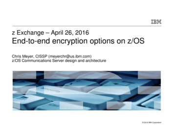
A flashing bPL is an indication that the AutomaticBumpless Transfer option is ON, the thermocouplehas failed, and the unit has invoked an AutomaticBumpless Transfer. TroubleshootingEither shut down and repair the brokenthermocouple, or:Press the AUTO% switch to display and recordthe average percent power value being output.Then place the unit in Manual mode, and enterthe percent power previously recorded.Dimensions:10 AMP: 7.2"W x 2.7"H x 8.6"D (18.29 x 6.86 x 21.84cm)NOTE: Use SSH/SHA/ESH-10-21 for 120VAC operation.Use SSH/SHA/ESH-10-22 for 240VAC operation.FUSE REQUIREMENTS:SSH/ESH: (2) ABC-10 cartridge fuses, F1 & F2SHA: (1) ABC-10 cartridge fuse, F2(Note: (2) spare ABC-10 fuses included with unit).SSH/SHA/ESH: (1) 160 mA sub-miniature fuse, or200 mA ceramic cartridge fuse, F3 (Check Unit)FRONT PANEL CONTROLS ANDINDICATORS (See figures 1, 2 and 3)INPUT SPECIFICATIONSThermocouple (T/C) Sensor: Type "J" (default) or Type“K” (optional), grounded or ntiometric input allows long distance T/C wiring.T/C Isolation: Isolated by control circuit power supply.Cold Junction Compensation: Automatic, better than0.02 F/ F. (0.01 C/ C)Open T/C Protection: Automatically inhibits power toheater in Auto mode.(Unless Automatic Bumpless Transfer is enabled)Reversed T/C Protection: Automatically inhibits powerto heater in Auto mode.(Unless Automatic Bumpless Transfer is enabled)Shorted T/C Protection: Automatically inhibits power toheater in Auto mode.(Unless Automatic Bumpless Transfer is enabled)Input Type: PotentiometricInput Impedance: 22 Meg ohms.Input Protection: Diode clamp, RC filter, and fusible linkresistor R4. (see figure 8)Input Amplifier Stability: 0.02 F/ F (0.01 C/ C)Input Dynamic Range: 1000 F (537 C) with J-type,1000 F (537 C) with K-type.Common Mode Rejection Ratio: Greater than 100 db.Power Supply Rejection Ratio: Greater than 90 db.1. DIGITAL LED MULTI-FUNCTION DISPLAY &DISPLAY MODE INDICATORS: Indicators are located inthe display at the top left of each digit. Three 7-segment,digital displays indicate process temperature, % poweroutput, operational modes, and diagnostic codes.Load Indicator: LED in display window illuminates whenpower is being supplied to the heater.(also blinks during Smart Start ).Manual Control Indicator: LED in display windowilluminates when in Manual mode.(also blinks after an Automatic Bumpless Transfer)OUTPUT SPECIFICATIONSVoltage/Power Capability:10 AMP: 120/240 VAC nominal, single-phase.SSH-10-21: 1200 watts @120 VACSSH-10-22: 2400 watts @240 VACSHA-10-21: 1200 watts @120 VACSHA-10-22: 2400 watts @240 VACESH-10-21: 1200 watts @120 VACESH-10-22: 2400 watts @240 VACOutput Drive: Internal solid-state triac, triggered by ACzero crossing pulses.Overload Protection:10 AMP: Fuses are provided on both sides of AC line.(Except SHA)Transient Protection: dv/dt and transient pulsesuppression included.Power Line Isolation: Optically, and transformerisolated from AC lines. Isolation voltage is greater than2500 volts.ELECTRICAL POWER SPECIFICATIONSSupply Voltage: 240 or 120 VAC 10% -20%Frequency: 50/60 HzDC Power Supplies: Internally generated, regulated andcompensated.Unit power usage: Less than 5 watts, excluding load.EE-000122-2006 REV: BFigure 2 - Pushwheel &Auto / Manual / % Power SwitchShorted Thermocouple (T/C) Indicator: Digital displayalternates "SHO" with process temperature.Open T/C Indicator: Digital display alternates "OPE"with process temperature. (typically "999")Reversed (Backward) T/C Indicator: Digital displayalternates “bAC” with process temperature.Degrees F/C Indication: At power up, the unit willdisplay " F" or " C" for three seconds, depending on theposition of function enable switch S4-7.Bumpless Transfer Indication: If a thermocouple faultoccurs with the Automatic Bumpless Transfer featureenabled, (S4-4 switched ON) the unit will display "bPL"alternating with the process temperature, and theappropriate thermocouple fault code.("SHO", bAC", or "OPE")Smart Start Override Disable: Digital display alternates"Loc" with process temperature during Smart Start if S4-2is ON.The display will alternate “Loc” “Err” with processtemperature after the completion of Smart Start, if thefront panel settings were changed during Smart Start.D-M-E SSH, SHA, & ESH User’s ManualPage 5
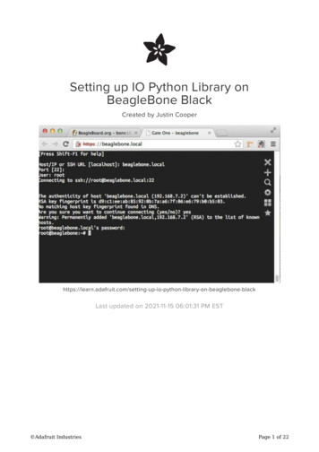
WIRING THE LOADWiring the unit is simple. Remove the side screw on themating connector, (included with the unit), and removethe insert from the hood shell. Then pull the wiresthrough the rear side of the connector hood shell andattach them as shown below by securing each wire in theproper hole and turning the screw to tighten. Commonmistakes in wiring can cause severe unit malfunctions.Please exercise caution when wiring the connector to theheating element and thermocouple. The SSH/SHA andESH wiring diagrams are shown below.Figure 3 – SSH-10-22 Unit2. TEMPERATURE DEVIATION LIGHTS: Indicateamount of deviation from setpoint temperature. An outerlight blinks when extreme over or under temperaturecondition /- 40 F ( /- 23 C) exists.Temperature Deviation Indicators: Five separateLED’s: /-20 F/11 C (Red), /-10 F/5 C (Yel low),0 F/0 C (Green)3. SETPOINT / % POWER ADJUSTMENT: Three-digitpushwheel adjusts setpoint (Auto), or % power (Manual).Auto Setpoint Control Range: 0 to 999 F, 0 to 537 C.Resolution: 1 F (1 C)Manual (% Power) Control: Right two digits of threedigit pushwheel.Manual (% Power) Control Range: 0 to 99%.4. AUTO / MANUAL / % AUTO SWITCH: Toggle switch,selects Auto, (setpoint temp.) or Manual (% power)control modes.Lower momentary position displays the percent poweroutput in Auto mode, or percent power AutomaticBumpless Transfer value in the case of a thermocouplefault.5. POWER ON/OFF SWITCH: Controls AC power to unit.16 amp rocker switch, UL, CSA, VDE approved.REAR PANEL (See figure 4)The rear panel has several items of interest to the user.First, the line cord is international and has 3 colors ofwires; these should be wired as follows: Brown (Line),Blue (Neutral), and Green/Yellow (Earth Ground).Second, the unit has 2 fuse-holders, each has an ABC10fuse installed (Only 1 fuse for SHA model). To access thefuse, disconnect power, insert a screwdriver into theplastic fuse holder slot, press inward slightly and turncounter-clockwise.Third, the power/thermocouple connector is mounted onthe rear panel. (See figure 5 for wire connections)Figure 5 - Connector Wiring DiagramsFUNCTION ENABLE -5S4-6S4-7Remote Boost Enable (*N/A FOR SSH/SHA/ESH*)Add 10% BoostAdd 20% BoostAuto Boost EnablePower Off Enable (*N/A FOR SSH/SHA/ESH*)Gain Cut (Normal/Fast Load)Standby Heat Enable (*N/A FOR SSH/SHA/ESH*)Smart Start (SS) Override DisableLights Out EnableAuto Bumpless EnableSHO LongSHO DisableDeg F/CFigure 6 – Function Enable SwitchesTEMPERATURE MODE F/ CTo operate the unit in the F (degrees Fahrenheit) mode,place switch S4-7 in the OFF position. To operate theunit in the C (degrees Centigrade) mode, place swi tchS4-7 in the ON position. (see figures 6 and 8) The modeof operation is displayed on startup as either " F" or " C".Figure 4 - Rear Panel of SSH UnitAUTOMATIC BUMPLESS TRANSFER"Automatic Bumpless Transfer" is defined as athermocouple failure causing the unit to automaticallyswitch into manual percent power mode, if the unit haslearned an average percent power. (The SSH, SHA orEE-000122-2006 REV: BD-M-E SSH, SHA, & ESH User’s ManualPage 6
ESH requires approximately 10 minutes of stabletemperature control to learn an average percent power)To enable Automatic Bumpless Transfer, place switchS4-4 in the ON position. To disable the AutomaticBumpless Transfer option, place switch S4-4 in the OFFposition. If disabled, the power output will be inhibitedafter a thermocouple fault occurs. The user will then haveto place the unit in Manual mode to gain control of theoutput power.With an Automatic Bumpless Transfer active, the unit willalso enter an alarm state. The display will alternatebetween "bPL" ("bumpless"), the diagnostic code for thethermocouple fault, and the process temperature. Toclear the alarm, push the AUTO% switch to view theaverage percent power being used, place the unit inManual mode and enter that percent power.With Automatic Bumpless disabled, the unit will still learnthe average percent power, but the user must press theAUTO% switch, and record the average percent powerprior to a thermocouple failure. Upon a thermocouplefault, the unit will inhibit output power, and will enter analarm state.The appropriate diagnostic code willalternate in the display with the process temperature.The user must then place the unit in Manual mode andenter the recorded percent power. This action will clearthe alarm state.LIGHTS OUT FEATUREThe unit can be programmed to shut off the digital LEDdisplay during stable Auto mode operation.To enable this option, set switch S4-3 to ON. After theunit achieves stable operation about setpoint for 10minutes, the digital LED display will turn off. Only thegreen deviation LED will be on.The display will turn back on automatically should analarm condition occur, if any of the front panel switchsettings are changed, or if the process temperaturedeviates more than /-10 F in temperature.It is recommended that the AUTO% switch be used totemporarily restore the display manually. The display willthen turn off again after five minutes of stable operationabout setpoint in Auto mode.SMART START OVERRIDE DISABLEThis Smart Start unit incorporates an option to overridethe Smart Start feature in Auto mode by toggling theAuto/Manual switch to Manual and then back to Auto. Bysetting switch S4-2 to ON, this override can now bedisabled. With switch S4-2 set to ON, the unit will display"Loc" alternating with the process temperature duringSmart Start. All front panel switch changes will beignored during Smart Start. If the user changes any ofthe front panel settings during Smart Start, the unit willcontinue to display "Loc" to indicate that the front panel isstill "locked out". After Smart Start is complete, the unitwill check for front panel settings changes, and thendisplay “Loc” “Err” alternating with the processtemperature if any changes have occurred. Output powerwill still be active.If the unit is operating in Auto mode with a processtemperature above 212 F, (100 C) the user must turn theunit off, and change the settings back to their initialpositions, then turn the unit back on. The unit will resumecontrolling to the selected setpoint. If the processtemperature is below 212 F, (100 C) the unit will r estartSmart Start.If the unit is operating in Manual mode, turn the unit off,and change the settings back to their initial positions,EE-000122-2006 REV: Bthen turn the unit back on. The unit will restart the SmartStart process.Setting switch S4-2 to ON also activates a new SmartStart feature in Manual mode. With S4-2 ON, a unit inManual mode will ramp from zero percent to setpointpercent power over a 4-1/2 minute period, thus mimickingSmart Start in Auto mode. "Loc" will be displayed in thismode also. “Loc” “Err” will also be displayed afterward, ifthe user attempts changes to the front panel settings.DESENSITIZING "SHO"Shorted Input override, SHO, is defined as a conditionwhen the thermocouple is shorted and the unit does notdetect a rising temperature that corresponds to the outputpower being delivered. If the temperature rise does notchange at a rate of more than 2 F in 90 seconds, t his isinterpreted as a Shorted Input.Sometimes a 2-degree rise in 90 seconds is toosensitive. If this is the case, the unit can be desensitizedto this situation, or the diagnostic can be totally shut off.Switch S4-5 ("SHO Long") changes the sensitivity to 3degrees in 255 seconds. Switch S4-6 ("SHO Disable")turns this diagnostic totally off. It is highly recommendedthat normal sensitivity be tried first. It should be sufficientfor all nozzles and most manifolds. Large hot runnermanifolds and molds may require desensitization. TheSHO Disable feature should only be considered as a finalresort.AUTO BOOSTUpon startup, any unit in Auto mode that has this featureenabled will increase the setpoint temperature accordingto the settings of switches S1-2 and S1-3 after thecompletion of Smart Start. This function is useful forincreasing temperature of nozzles for initial startup of thehot runner system, but doesn't require an external signal.If a thermocouple fails during Auto Boost, the unit willinhibit output power and will enter an alarm state.To enable this option, switch S1-4 must be set to ON,and either or both switches S1-2 and S1-3 must be ON.This allows the user to select the units in the system thatwill react to Auto Boost. Switch S1-2 adds 10% to theentered setpoint. S1-3 adds 20% to the entered setpoint.Having both S1-2 and S1-3 ON adds 30% to the enteredsetpoint. For example; if S1-2 is ON and the enteredsetpoint is 500 degrees, power up will cause the unit toassume a 550 degree setpoint for a period of 3 minutesafter the completion of Smart Start. After 3 minutes, theunit will return to the 500 degree setpoint.GAIN ADJUSTMENT (Fast Load PID)If temperature oscillates during operation (Fast Load), theuser can compensate for this by turning S1-6 to OFF.This is recommended for coil heaters with ungroundedinternal thermocouples or very small nozzles.K TYPE THERMOCOUPLE SELECTThe SSH, SHA, and ESH units can be converted for a Ktype thermocouple input by re-configuring thethermocouple type select jumpers. (see figures 7 and 8)Remove jumpers J5 and J6, and install jumpers J7, J8,and J21 for a K type thermocouple input.After converting the T/C to K type, or back to a J type, themodule will require re-calibration.D-M-E SSH, SHA, & ESH User’s ManualPage 7
CALIBRATION PROCEDURE – J OR KTYPE T/C (See figure 7 and 8)REPLACEMENT PARTS LIST1. With the top cover removed, power the unit on, andwait 10-15 minutes for it to warm up.2. Attach a thermocouple simulator (I.E. Omega model#CL25) to the thermocouple inputs and set the simulationtemperature to 200 F (93 C) for J- type T/C.(400 F (204 C) for K-type T/C)3. Adjust the ZERO trim pot, R13, to read 200 F (93 C)on the display for J-type T/C.(400 F (204 C) for K-type T/C)4. Set the simulation temperature to 800 F (427 C) for Jtype T/C. (650 F (343 C) for K-type T/C)5. Adjust the GAIN trim pot, R18, to read 800 F (427 C)on the display for J-type T/C.(650 F (343 C) for K-type T/C)6. Repeat steps 2 through 5 until no further trim potadjustment is needed.7. Turn power off, remove the thermocouple simulator,and re-attach the top cover.To meet warranty requirements, use only DME parts.ABC10F1, F2, Fuse, 10 Amp, 250 Volt,The use of lower amperage fuses forincreased protection is recommended.Power Rocker Switch, 16 Amp, 250 VACRPM0008T1, Transformer, 240/120 VoltRPM0009U5, Triac DriverRPM0010R4, Flameproof Fusible link resistorRPM0050WARNING! DO NOT SUBSTITUTESetpoint pushwheel switch assembly, onfront panel.Q1, Triac, 40 Amp, 800 VoltSW3, 3 position switch on front panelF3, Fuse, 160 mA, 250 V, Sub-miniature(Check Module for correct fuse RPM#)F3, Fuse, 200mA, 250 V, Cer. Cartridge(Check Module for correct fuse RPM#)RPM0053RPM0054RPM0056RPM0090RPM0107RETURN POLICYThe D-M-E SSH ,SHA, and ESH units are warranted for3-years parts and labor, excluding fuses, triac, &calibration. Contact D-M-E Customer Service for returnauthorization for repairs, or warranties. Replacementparts are also available through the Customer ServiceDepartment.D-M-E Customer ServiceFigure 7 - Thermocouple Type Jumpers &Calibration PotentiometersIn U.S.:1-800-626-6653In Canada:1-800-387-6600SERVICE CENTER U.S.A.D-M-E WORLD HEADQUARTERS29111 STEPHENSON HIGHWAYMADISON HEIGHTS, MICHIGAN 48071Fax: (800) 461-9965Internet: www.dme.netSSH , G-Series , Smart Series , Smart Start , andD-M-E are all registered trademarks of D-M-E CompanyLLC.AUSTRALIA:Die Mould Equipment Pty. Ltd.ABN: 69 136 336 840P.O. Box 1156,Unanderra, N.S.W. 2526, AustraliaTelephone: 61 (0) 2 4272 3700Fax: 61 (0) 2 4271 3099Internet: http://www.diemouldequipment.com.au/EE-000122-2006 REV: BD-M-E SSH, SHA, & ESH User’s ManualPage 8
FRONT PANEL CONTROLS & INDICATORS DIAGNOSTIC TEST PROCEDUREEE-000122-2006 REV: BD-M-E SSH, SHA, & ESH User’s ManualPage 9
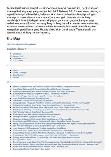
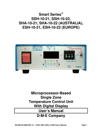
Figure 8 - Main Printed Circuit BoardAUTO/MAN/%PWRSWITCH (S3)DME #RPM0056POWER SWITCHDME #RPM0008PUSHWHEELSWITCHDME #RPM0053FUNCTIONENABLESWITCHESTRANSFORMER120/240 VOLTAGEJUMPERSCALIBRATIONPOTENTIOMETERSFUSE F3(PROTECTSELECTRONICS)DME #RPM0107CHECK PRODUCTFOR CORRECTFUSE RPM#THERMOCOUPLETYPE JUMPERSTRIAC DRIVERDME #RPM0010TRIACDME #RPM0054EE-000122-2006 REV: BFUSIBLE LINK(RESISTOR R4)USE ONLYFLAME-PROOFTYPE(DME# RPM0050)FUSES(LOAD FUSES)F1, F2DME #ABC10*F2 ONLY FOR SHA*D-M-E SSH, SHA, & ESH User’s ManualPage 10
ECN’sECN-E068302/15/10Added SHA model informationMisc. content & figure images revisedDocument Number was ED-0130-OT-026APPROVALCHECKED BY: T. JOHNSTONDATE: 02/15/10APPROVED BY: T. JOHNSTONDATE: 02/15/10EE-000122-2006 REV: BD-M-E SSH, SHA, & ESH User’s ManualPage 11
SSH-10-21, SSH-10-22, SHA-10-21, SHA-10-22 (AUSTRALIA), ESH-10-21, ESH-10-22 (EUROPE) Microprocessor-Based Single Zone Temperature Control Unit With Digital Display . If the unit is operating in Manual mode, turn the unit off, and change the settings back to their initial positions, then turn the unit back on. The