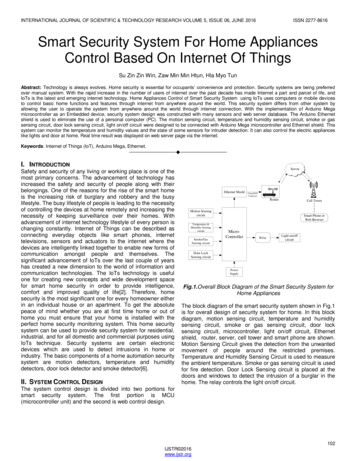
Transcription
Draw IT 2016 for AutoCADTutorial for System ScaffoldingVersion: 16.0Copyright Computer and Design Services LtdGLOBAL CONSTRUCTIONSOFTWARE AND SERVICES
Tutorial for System ScaffoldingContentsIntroduction . 1Getting Started. 21Getting Started with AutoCAD . 31.1Step 1: Placing the Elevation, Side and Plan Views. 41.1.1Step 1a: Getting Started. 51.1.2Step 1b: Locating the Cuplok Tool Palette . 61.1.3Step 1c: Placing the Scaffold Views onto the Drawing . 71.2Step 2: Entering the Scaffold Dimensions . 101.2.1Step 2a: Setting the Number of Lifts . 111.2.2Step 2b: Setting the Number of Bays . 121.2.3Step 2c: Defining the Guard Rails and Boards . 131.3Step 3: Adding the Facade Bracing . 151.4Step 4: Drawing the Ladders and Boards . 181.4.1Step 4a: Adding Ladders to the Elevation, Side and Plan Views . 181.4.2Step 4b: Adding the Boards to the Plan View . 221.5Step 5: Drawing a Gable End . 251.6Step 6: Annotating the Drawing. 291.6.1Step 6a: Adding Dimensions . 291.6.2Step 6b: Adding Stamps . 321.6.3Step 6c: Title Block . 331.7Step 7: Drawing an Irregular Scaffold . 351.7.1Step 7a: Exploding the Scaffold into Components. 351.7.2Step 7b: Adding Double Guardrail Frames. 361.7.3Step 7c: Adding a Bridge . 38Feedback . 40Copyright Computer and Design Services Limited
Tutorial for System ScaffoldingIntroductionThank you for choosing CADS SMART Scaffolder.SMART Scaffolder Draw IT 2016 is a new module that makes it easy to draw professional scaffoldengineering drawings using AutoCAD or AutoCAD LT.With Draw IT 2016 you can simply drag and drop scaffold components onto the drawing and producedrawings that conform to industry standard practices. SMART Scaffolder Draw IT 2016 is suppliedwith components from several manufacturers of tube-and-fitting and system scaffolding, includingthe SGB Cuplok catalogue.Intelligent scaffolding blocks are provided for both tube-and-fitting and system scaffolding, whichallow you to quickly produce drawings simply by defining the scaffold dimensions.This tutorial aims to guide you through using the Draw IT 2016 tools to create professional scaffoldingengineering drawings using system scaffolding components.1Copyright Computer and Design Services Limited
Tutorial for System ScaffoldingGetting StartedPlease read the SMART Scaffolder Draw IT 2016 user manual before you start. All ofthe AutoCAD commands used in this Tutorial are described in the User Guide.You can start the application by either double-clicking the icon on your desktop, or by selecting theapplication from Start All Programs CADS.In Windows 8 or Windows 8.1, you can alternatively select the Draw IT Windows 8 tile.Draw IT (AutoCAD 2016)AutoCAD will then open with Draw IT 2016 automatically loaded.If you start AutoCAD using the Draw IT icon then your scaffolding tools will be ready touse. Only start AutoCAD with the AutoCAD icon when you don’t want to use Draw IT.2Copyright Computer and Design Services Limited
Tutorial for System Scaffolding1 Getting Started with AutoCADThis tutorial has been written for Cuplok system scaffolding, but you can follow the samesteps to draw scaffolding with any other system that you have installed.This tutorial explains how to create a Cuplok system scaffold using AutoCAD. SMART Scaffolder DrawIT allows you to easily draw system scaffolding in two ways:1. You can use dynamic scaffolds to very quickly draw regular scaffolding;2. The individual components of the Cuplok catalogue are provided. These can be dragged anddropped onto the drawing to build any shape of scaffolding.This tutorial demonstrates how to use a dynamic scaffold to quickly build a regular scaffold with agable end, including its plan and elevation views. It will also show how to use the drag and dropcomponents, which will enable you to build more complicated scaffolds using the same techniques.The steps involved are:1. Drag-and-drop the dynamic elevation view, side view and plan view onto the drawing;2. Enter the dimensions of the scaffold;3. Add facade bracing;4. Draw the ladders and boards;5. Add a gable end;6. Annotate the drawing with text and dimensions;7. ‘Explode’ the scaffold to draw advanced features such as a bridge.The tutorial concludes by demonstrating how to modify the scaffold to build an irregular shape or toaccount for special circumstances.3Copyright Computer and Design Services Limited
Tutorial for System Scaffolding1.1 Step 1: Placing the Elevation, Side and Plan ViewsThis step will demonstrate:1. Starting SMART Scaffolder Draw IT 2016;2. Finding the Cuplok tool palette;3. Dragging and dropping the dynamic Cuplok system scaffolding blocks onto the drawing.Once these steps have been completed the drawing will appear as follows:4Copyright Computer and Design Services Limited
Tutorial for System Scaffolding1.1.1 Step 1a: Getting StartedTo get started:1. Double click the Draw IT icon on the Windows Desktop.2. Select the A2 paper size using the Quick View Layouts option.To choose the layout that you want to use in AutoCAD 2009 / 2010, click the Quick View Layoutsbutton at the very bottom of the AutoCAD window:The Quick View Layouts button.You can then click on the paper size that you require:The other versions of AutoCAD use tabs along the bottom of the screen to perform the samefunction.3. Once the A2 layout is visible, double-click in the centre of the paper to activate the viewport. Thisis the area that you will be drawing into.5Copyright Computer and Design Services Limited
Tutorial for System Scaffolding1.1.2 Step 1b: Locating the Cuplok Tool PaletteThe AutoCAD tool palette allows you to drag and drop scaffolding components onto the drawing. Thepalette contains a number of tabbed pages, which can be clicked to display different types ofscaffolding components. For example there are tabbed pages for Cuplok dynamic components, tabbedpages that provide the catalogue of Cuplok components, and tabbed pages for tube-and-fittingcomponents.The tool palette should be visible in the AutoCAD window, as shown below.If the Tool Palette is not visible, click the View toolbar tab and then click on the ToolPalette icon on the Palettes panel.To activate the Cuplok components, click on the tab with the title: Cuplok Scaffold System. If this tab isnot visible, click on the stacked tabs at the bottom of the tool palette to see the complete list:Click on the stacked tabs with theleft mouse button to display thecomplete list of palettes andselect the Cuplok Scaffold Systemtab.6Copyright Computer and Design Services Limited
Tutorial for System Scaffolding1.1.3 Step 1c: Placing the Scaffold Views onto the Drawing1. Locate the Cuplok Scaffold System tab on the tool palette as described previously;2. To place the scaffold plan, click on the Plan icon in the palette;3. Move across to the drawing and click to position the scaffold plan on the drawing;4. When placing the scaffold plan allow enough room for the side elevation to be drawn to the left,as shown below.Make sure you double click inside the Viewport to activate it before you try to drag anddrop the scaffold plan.Click on the Plan.Click to drop the Plan onto the drawing.7Copyright Computer and Design Services Limited
Tutorial for System Scaffolding5. The next step is to place the front elevation onto the drawing so that it is aligned with the planview. This will be achieved by using an AutoCAD feature known as inference.If you prefer you can use construction lines to place the front and side elevationsinstead, as described in the Tube and Fitting Tutorial.It helps to zoom in by moving the mouse cursor over the plan view that you have just placed androlling the mouse wheel forward.Click on the Front Elevation tool from the Cuplok Scaffold System palette, move the mouse overthe first transom in the plan view, and hover it there for a second. Now move the mouse upwardand you will see a dotted line that is aligned with the transom position; if you click the mouse onthe dotted line the elevation and plan views will be aligned.First click on the Front Elevation tool Hover the mouse over thefirst transom for a second Then move the mouseupward and click on thedotted inference line.8Copyright Computer and Design Services Limited
Tutorial for System Scaffolding6. The Side Elevation is placed in a similar way, this time by using a horizontal inference line thatstarts from the front elevation drawing.It helps to first pan the view to clear some space: hold the mouse wheel down, move the mouseto the right, then release the mouse wheel.Click on the Side Elevation tool from the Cuplok Scaffold System palette, move the mouse over thefirst base plate in the front elevation view, and hover it there for a second. Now move the mouseto the left to create a horizontal inference line and click on it to place the side elevation.This completes placing the scaffold plan, front elevation, and side elevation.9Copyright Computer and Design Services Limited
Tutorial for System Scaffolding1.2 Step 2: Entering the Scaffold DimensionsThis step will demonstrate how to:1. Change the number of lifts and bays in the scaffold.2. Change the board and guard rail details.The views of the scaffold placed in Step 1 are AutoCAD dynamic blocks. A dynamic block hasintelligence built into it that allows it to be changed as you work. The Draw IT scaffold dynamic blocksallow you to change the dimensions of the scaffold using grips.To activate the grips for a dynamic block, click on it so that it becomes selected. To deactivate thegrips press the Esc key to clear the selection.Some of the dynamic blocks have additional parameters that are only accessible via the propertiespalette.If the AutoCAD Properties Palette is not visible, click the View toolbar tab and then clickon the Properties icon on the Palettes panel.10Copyright Computer and Design Services Limited
Tutorial for System Scaffolding1.2.1 Step 2a: Setting the Number of Lifts1. Click on the front elevation of the scaffold to activate it.2. Click on the Number of Lifts grip, shown in the previous diagram, and select 3 Lifts.3. Now click on the side view of the scaffold to activate it and set its number of lifts to 3 in thesame way.11Copyright Computer and Design Services Limited
Tutorial for System Scaffolding1.2.2 Step 2b: Setting the Number of BaysThe next step is to set the number of bays of scaffolding. At this stage regular bays of 2.5m will beused.1. Click on the front elevation of the scaffold to activate it.2. Click on the Scaffold Length grip and move it to the right. You will see a marker at each bay position:click the left mouse button once the scaffold is 15000mm long, when the mouse cursor is at thesixth marker:3. Repeat this process for the plan view by clicking on it to activate it, clicking on its Scaffold Lengthgrip, and clicking the mouse past the sixth marker.12Copyright Computer and Design Services Limited
Tutorial for System Scaffolding1.2.3 Step 2c: Defining the Guard Rails and BoardsThe next stage is to define which lifts are to be boarded and how many guard rails to place at each lift.The scaffold will have every lift boarded, including the foot lift, and protected by double guard rails bydefault, but this can be changed by using the grips in a similar way to the entry of the lifts and bays.1. Click on the front elevation to activate it.2. Click on the Guard Rails grip at the foot lift and choose None; the guard rails and boards will beremoved.3. Next, click on the Guard Rails grips at the first and second lifts and select Single Guard Rail.The boards are switched off by default when the guard rails are removed or set to singlerails.However, you can switch them back on again by using the Boards grip if you wish, forexample if drawing a birdcage scaffold.13Copyright Computer and Design Services Limited p
AutoCAD will then open with Draw IT 2016 automatically loaded. Please read the SMART Scaffolder Draw IT 2016 user manual before you start. All of the AutoCAD commands used in this Tutorial are described in the User Guide. If you start AutoCAD using the


![Unreal Engine 4 Tutorial Blueprint Tutorial [1] Basic .](/img/5/ue4-blueprints-tutorial-2018.jpg)


