Transcription
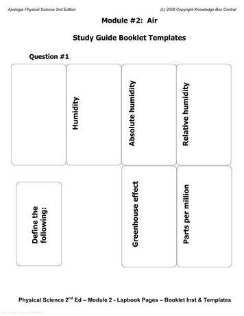
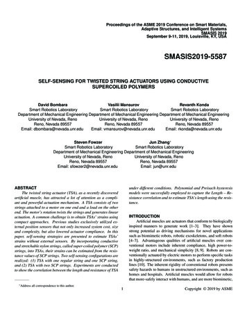
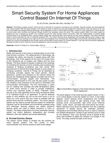
INTERNATIONAL JOURNAL OF SCIENTIFIC & TECHNOLOGY RESEARCH VOLUME 5, ISSUE 06, JUNE 2016ISSN 2277-8616Smart Security System For Home AppliancesControl Based On Internet Of ThingsSu Zin Zin Win, Zaw Min Min Htun, Hla Myo TunAbstract: Technology is always evolves. Home security is essential for occupants‘ convenience and protection. Security systems are being preferredover manual system. With the rapid increase in the number of users of internet over the past decade has made Internet a part and parcel of life, andIoTs is the latest and emerging internet technology. Home Appliances Control of Smart Security System using IoTs uses computers or mobile devicesto control basic home functions and features through internet from anywhere around the world. This security system differs from other system byallowing the user to operate the system from anywhere around the world through internet connection. With the implementation of Arduino Megamicrocontroller as an Embedded device, security system design was constructed with many sensors and web server database. The Arduino Ethernetshield is used to eliminate the use of a personal computer (PC). The motion sensing circuit, temperature and humidity sensing circuit, smoke or gassensing circuit, door lock sensing circuit, light on/off circuit were designed to be connected with Arduino Mega microcontroller and Ethernet shield. Thissystem can monitor the temperature and humidity values and the state of some sensors for intruder detection. It can also control the electric applianceslike lights and door at home. Real time result was displayed on web server page via the internet.Keywords: Internet of Things (IoT), Arduino Mega, Ethernet.—————————— ——————————I. INTRODUCTIONSafety and security of any living or working place is one of themost primary concerns. The advancement of technology hasincreased the safety and security of people along with theirbelongings. One of the reasons for the rise of the smart homeis the increasing risk of burglary and robbery and the busylifestyle. The busy lifestyle of people is leading to the necessityof controlling the devices at home remotely and increasing thenecessity of keeping surveillance over their homes. Withadvancement of internet technology lifestyle of every person ischanging constantly. Internet of Things can be described asconnecting everyday objects like smart phones, internettelevisions, sensors and actuators to the internet where thedevices are intelligently linked together to enable new forms ofcommunication amongst people and themselves. Thesignificant advancement of IoTs over the last couple of yearshas created a new dimension to the world of information andcommunication technologies. The IoTs technology is usefulone for creating new concepts and wide development spacefor smart home security in order to provide intelligence,comfort and improved quality of life[2]. Therefore, homesecurity is the most significant one for every homeowner eitherin an individual house or an apartment. To get the absolutepeace of mind whether you are at first time home or out ofhome you must ensure that your home is installed with theperfect home security monitoring system. This home securitysystem can be used to provide security system for residential,industrial, and for all domestic and commercial purposes usingIoTs technique. Security systems are certain electronicdevices which are used to detect intrusions in home orindustry. The basic components of a home automation securitysystem are motion detectors, temperature and humiditydetectors, door lock detector and smoke detector[6].II. SYSTEM CONTROL DESIGNServerEthernet ShieldUsing RJ45ConnectorRouterCell TowerMotion SensingcircuitTemperature &Humidity SensingcircuitSmoke/GasSensing circuitSmart Phone orWeb BrowserMicroControllerRelayLight on/offcircuitDoor LockSensing circuitPowerSupplyFig.1.Overall Block Diagram of the Smart Security System forHome AppliancesThe block diagram of the smart security system shown in Fig.1is for overall design of security system for home. In this blockdiagram, motion sensing circuit, temperature and humiditysensing circuit, smoke or gas sensing circuit, door locksensing circuit, microcontroller, light on/off circuit, Ethernetshield, router, server, cell tower and smart phone are shown.Motion Sensing Circuit gives the detection from the unwantedmovement of people around the restricted premises.Temperature and Humidity Sensing Circuit is used to measurethe ambient temperature. Smoke or gas sensing circuit is usedfor fire detection. Door Lock Sensing circuit is placed at thedoors and windows to detect the intrusion of a burglar in thehome. The relay controls the light on/off circuit.The system control design is divided into two portions forsmart security system. The first portion is MCU(microcontroller unit) and the second is web control design.102IJSTR 2016www.ijstr.org
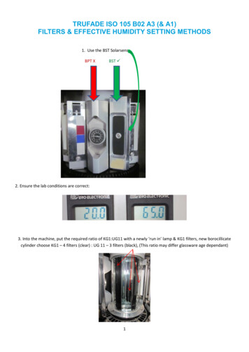
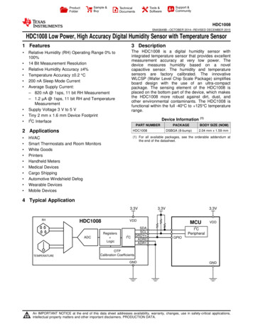
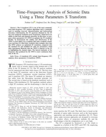
INTERNATIONAL JOURNAL OF SCIENTIFIC & TECHNOLOGY RESEARCH VOLUME 5, ISSUE 06, JUNE 2016The smart security system for home appliances based on IOTshas the capabilities to control the light ON/Off and monitorthe sensors shown in Fig.3. In the Fig.3, the alarm system1 isused for smoke or gas sensor and the alarm system2 for PIRsensor. And then, the alarm system3 is used for hall-effectsensor. ENC28J60 Ethernet module with RJ45connector wasused to connect each other Arduino Mega microcontroller andweb server data. The Ethernet is interfaced to the ArduinoMega via the Arduino SIP pins. Arduino Mega microcontrollerimplemented with C language, using IDE comes with themicrocontroller itself. Arduino software is responsible forcollecting event from connected sensors, then apply action toactuators and pre-programed in the server. Another work is toreport and record the history in the server database.StartEnter Domain NameSever not foundDomain namecorrect?NoYesRead data fromsensors via the internetYesSend user commandto relay?2.1.1. Sensor SectionThe sensor section is considered with the following detectionof: Smoke or gas detection Motion detection Door lock detection Temperature and humidity detectionRead command andchange relay stateNoData Logging andmonitoring on serverDisplay real time statuson webpage via internetNoISSN 2277-8616Exit?YesEndFig.2. Flowchart of general processing for proposed homesecurity systemWhen the corrected domain name enters, the Arduino Megamicrocontroller reads smoke signal, magnetic signal, roomtemperature and moisture, and motion detector. It will sendthese data to the web server page via the internet. The relaystate will be changed when the command and data isreceived. The microcontroller will read command and changerelay state. And then, the data will be recorded and displayedon web server database. The real time status will display onweb server page through the internet.A. Smoke or Gas detectionThe smoke or gas sensor is used to detect the gas leakageand smoke occurring in home. This is used to detect gaseslike LPG/I butane/ propane/ methane/ alcohol/ hydrogen/smoke. There are different types of gas sensor which detectsdifferent gases according to different concentration parameter.Here we are using MQ-2 gas and smoke sensor. MQ2 is asemiconductor type sensor, which can appropriately sense thepresence of smoke, LPG, methane, butane, propane andother hydrocarbon combustible gases. Whenever thegas/smoke leakage is detected by the sensor, the circuit startsworking with 5 volts supply.StartDefine I/O PinRead Smoke or gassensor analog value2.1. MCU (Microcontroller Unit)The Microcontroller unit is separated into two sections. Firstsection is sensor section and the second one is driver section.NoAnalog value 400Buzzer ONENC28J60 Ethernet modulewith RJ45 connectorBuzzer g Input2Digital Input/Output1Humidity &TemperaturesensorD11D10AREFArduino VCC GND OUTGNDStop n/offFig.4. Overall Flowchart of Smoke or Gas sensor rmSystem2TXRXRelay2AlarmSystem1BuzzerRelay1Fig.3. Overall Circuit Diagram of the Smart Security SystemThe flowchart represents loop function of smoke or gassensing shown in Fig.4. Firstly the microcontroller will defineinput/output pins. Until the program is restarted, the signal willbe generated repeatedly. When sensed smoke or gas analogvalue is greater than 400, Arduino pin for buzzer will be high.When sensed smoke or gas analog value is less than 400,Arduino pin for buzzer will be stopped.103IJSTR 2016www.ijstr.org
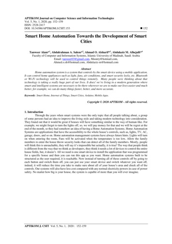
INTERNATIONAL JOURNAL OF SCIENTIFIC & TECHNOLOGY RESEARCH VOLUME 5, ISSUE 06, JUNE 2016B. Motion detectionMotion detectors are used to detect the unwanted movementof people around the restricted premises. Hence, the passiveInfrared (PIR) sensors could be used as a motion detector ifthere is some movement around the restricted premises. Thepassive Infrared sensor is used as a motion detector in thesystem. The PIR (Passive Infra-Red) sensor is a pyroelectricdevice that detects motion by measuring changes in theinfrared level emitted by surrounding objects. This motion canbe detected by checking for a high signal on a signal I/O pin.PIR sensor is electronic devices which is used in somesecurity systems to detect an infrared emitting source. Allliving beings whose temperature is anything above absolutezero (-273.15 C or -459.67 F), emits infrared radiation. Thisradiation (energy) is invisible to the human eye but can bedetected by electronic device designed for such a purpose.StartDefine I/O PinRead analog valuefrom Hall-effectsensorNoNoYesBuzzer ONStop Sensing?YesStartFig.6. Flowchart of Door lock sensingAbove flowchart shows how hall-effect sensor sensing work.When sensed magnetic analog value is greater than 510,Arduino pin for buzzer will be high. When sensed magneticanalog value is less than 510, Arduino pin for buzzer will bestopped. Until program stop, the routine will be repeatedinfinitely.Define I/O PinRead PIR sensorDigital valueIf PIR 1?Analog value 510Buzzer OFFStartNoISSN 2277-8616YesFig.5. Overall Flowchart of PIR sensor sensingD. Temperature and humidity detectionFor temperature and humidity detection, DHT11 is used. TheDHT11 is a basic, ultra low-cost digital temperature andhumidity sensor. It uses a capacitive humidity sensor and athermistor to measure the surrounding air, and spits out adigital signal on the data pin (no analog input pins needed). Itis fairly simple to use, but requires careful timing to grab data.The overall circuit diagram of humidity and temperaturedetection circuit is shown in Fig.3. This is to design themonitoring system for smart security system. The humidity andtemperature values will be display on user interface.The flowchart shown in Fig.5 is the operation of the PIRsensor sensing. Whenever the PIR sensor digital value is high,arduino input pin will be high and buzzer will be energizing asbeat of alarm signal.2.1.2. Driver SectionThe driver section includes the relay and buzzer for smartsecurity system. The buzzer is used for alarm system andrelay is used for light ON/OFF.C. Door Lock detectionThe intrusion sensors are placed at the doors and windows todetect the intrusion of a burglar in the home. The intrusiondetector is used to give extra security along with otherdetectors. The hall-effect proximity sensor is used for intrusiondetector. A hall-effect proximity sensor is a magnetic sensorbased on the hall effect of the magnet. Voltage perpendicularto both the current and the field is generated when a currentcarrying conductor is placed into a magnetic field and thisprinciple is known as the Hall Effect. For the installation of theproximity sensor, a magnet is attached to the frame of the dooror window, whereas the sensor is attached to the door orwindow itself. The magnet and the sensor should be installedsuch that they are close to each other whenever the door orwindow is closed.2.2. Web Control DesignThe web control design is composed of two portions. The firstportion is the database logging system and the second one isthe user interface.High arduino input pinBuzzer ONLow arduino input pinBuzzer OFFNoStop Sensing?YesStartHardwareEthernet ShieldDatabaseArduino MegaMicrocontrollerSensorsWeb ServerWeb ServerActuatorUserInterfaceFig.7. Block Diagram of the Data Flow For Home SecuritySystemThe block diagram of the data flow for home security system isshown in Fig.7. The hardware including Ethernet shield,Arduino Mega microcontroller, sensors and actuator, web104IJSTR 2016www.ijstr.org
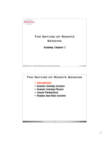
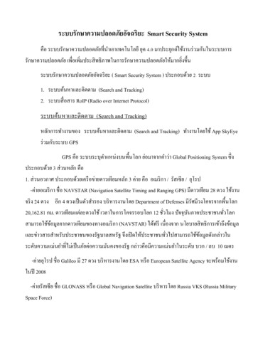
INTERNATIONAL JOURNAL OF SCIENTIFIC & TECHNOLOGY RESEARCH VOLUME 5, ISSUE 06, JUNE 2016server, database and user interface are represented in thisblock diagram. In the hardware portion, when the ArduinoMega microcontroller achieves 5V supply, it will collect datafrom sensors. And then, the Arduino will send data to webserver with POST method. The post.php web server pagereads the data from the Arduino and will change the data tothe relative variables. This page will send the relative variablesto the database. The data logging in the database will alsosend to the index web server page and then this web serverwill monitor to the user interfaced.ISSN 2277-8616The user interface was implemented not only for monitoringsystem but also for control the light ON/OFF. The user canalso easily watch the real time status and control light ON/OFFfrom relay control on the webpage thought the web server viathe internet.III. IMPLEMENTATIONStartDefine I/O pin2.2.1. Database logging systemThe smart security system for home appliances control dealswith information that has to be logged in database andmonitored through web page on browser.NoIf(millis()%(t1Hz*3) 0)YesRead sensingdataIf(millis()%(t1Hz*8) 0)Fig.8. PhpMyAdmin in browser to administer databaseNoYesThe Figure.8 shows the PhpMyAdmin page in browser. Nowthe data
Overall Circuit Diagram of the Smart Security System Arduino pin for buzzer will be stopped. The smart security system for home appliances based on IOTs has the capabilities to control the light ON/Off and monitor the sensors shown in Fig.3. In the Fig.3, the alarm system1 is used for smoke or gas sensor and the alarm system2 for PIR sensor. And then, the alarm system3 is used for hall-effect .