Transcription
OPTO-TOUCH OTB Series Optical Touch ButtonInstruction ManualMomentary Action Optical Touch Buttons Zero-force touch-activated photoelectric replacements for mechanical push buttonsMomentary-action touch buttons with SPDT electromechanical relay or solid-state outputsOptimized for easy mounting with a 30 mm threaded baseErgonomic design eliminates hand, wrist and arm stressPre-installed field covers protect the device and prevent inadvertent activationWARNING: Do not use this device for personnel protection Using this device for personnel protection could result in serious injury or death. This device does not include the self-checking redundant circuitry necessary to allow its use inpersonnel safety applications. A device failure or malfunction can cause either an energized (on) or deenergized (off) output condition.ModelsModel 1VoltageBlack CoverYellow CoverOTBVN6OTBVN6 W/YOTBVN6QDOTBVN6QD W/YOTBVP6OTBVP6 W/YOTBVP6QDOTBVP6QD W/YOTBA5OTBA5 W/YOTBA5QDOTBA5QD W/YOTBB5OTBB5 W/YOTBB5QDOTBB5QD W/YOTBVR81OTBVR81 W/YOTBVR81QDOTBVR81QD W/YOutputConnection 26-foot attached cableComplementary NPN (sinking) outputs10 V DC to 30 V DC4-pin 7/8 in. 16UNF quickdisconnect6-foot attached cableComplementary PNP (sourcing) outputs 4-pin 7/8 in. 16UNF quickdisconnect6-foot attached cable120 V AC5-pin 7/8 in. 16UNF quickdisconnect6-foot attached cable220/240 V ACSPDT electromechanical relay output5-pin 7/8 in. 16UNF quickdisconnect6-foot attached cable20 V AC or DC to 30 V AC or DC 35-pin 7/8 in. 16UNF quickdisconnectImportant. Read this before proceeding!The user is responsible for satisfying all local, state, and national laws, rules, codes, and regulations relating to the use of thisproduct and its application. Banner Engineering Corp. has made every effort to provide complete application, installation, operation,and maintenance instructions. Please contact a Banner Applications Engineer with any questions regarding this product.The user is responsible for making sure that all machine operators, maintenance personnel, electricians, and supervisors arethoroughly familiar with and understand all instructions regarding the installation, maintenance, and use of this product, and with themachinery it controls. The user and any personnel involved with the installation and use of this product must be thoroughly familiar1 To order a model with polycarbonate upper housing (others are polysulfone), add the suffix "L" to the model number. For example, OTBVN6L.2 Models with a quick disconnect require a mating cordset.M12 integral quick-disconnect models may be available. Add the suffix "H" to the quick-disconnect model number. For example, OTBVP6QDH orOTBVR81QDH. Contact Banner Engineering for availability.3 20 V DC to 30 V DC power may be applied without regard to polarity.Original Document28436 Rev. N29 October 202128436
OPTO-TOUCH OTB Series Optical Touch Buttonwith all applicable standards, some of which are listed within the specifications. Banner Engineering Corp. makes no claim regardinga specific recommendation of any organization, the accuracy or effectiveness of any information provided, or the appropriateness ofthe provided information for a specific application.EU Declaration of Conformity (DoC)Banner Engineering Corp. herewith declares that these products are in conformity with the provisions of the listed directives and allessential health and safety requirements have been met. For the complete DoC, please go to www.bannerengineering.com.ProductDirectiveOTB Series DC and AC ModelsEMC Directive 2014/30/EU, Low Voltage Directive 2014/35/EURepresentative in EU: Peter Mertens, Managing Director, Banner Engineering BV. Address: Park Lane, Culliganlaan 2F, bus 3,1831Diegem, Belgium.OverviewBanner Optical Touch Buttons (OTB) are touch-activated photoelectric switches designed to replace capacitive touch switches andmechanical push buttons. The OPTO-TOUCH's SPDT electromechanical relay or solid-state output (depending upon model) isactivated when a finger, introduced into the "touch area" (yoke) of the switch, interrupts the OPTO-TOUCH's infrared sensing beam.Banner Optical Touch Buttons are ergonomically designed to eliminate the hand, wrist, and arm stresses associated withmechanical push buttons. They require absolutely no physical pressure to operate. LED indicators light for "power on" and "outputactivated".All models are highly resistant to EMI, RFI, and ambient light interference. OTBs have a black polysulfone (or red polycarbonate)upper housing and fiber-reinforced thermoplastic polyester base. Polycarbonate models have the letter "L" in their model numbersuffix. Environmental considerations for use of the two types differ; see the specifications. The 30 mm threaded base on all modelsprovides easy mounting, and Banner Optical Touch Buttons are easily retrofitted to existing machines.Rugged polypropylene (TP) field covers are installed on all models to avoid inadvertent switch actuation due to objects (such asloose clothing or debris) that might accidentally block the sensing beam and to protect the device. The polypropylene material iscapable of absorbing high impact (even at low temperatures) and is highly resistant to abrasion and to damage by most chemicals.Safety Instruction: A field cover is installed on this OPTO-TOUCH. If this cover is missing or has become lostor damaged, contact Banner Engineering immediately for a no-charge replacement.Installing the OTBsInstall the OPTO-TOUCH Optical Touch Buttons so the environment does not adversely affect the means of actuation. Severecontamination of the touch area (yoke) of the switch or other environmental influences may cause slow response or false energized(on) conditions.Mount the buttons to protect them from accidental or unintentional operation.Consider ergonomic principles to avoid unnecessary fatigue in the installation of the hand controls. Install the touch buttons at aheight and in a location that will be comfortable for the user. See ANSI B11.TR1 Ergonomic Guidelines, and EN894 Safety ofMachinery-Ergonomic Requirements-Control Actuators for more information.Mount the buttons a safe distance from moving machine parts, as determined by the appropriate standard (for example, ANSIB11.19, ISO 13851). It must not be possible for the operator or other non-qualified persons to relocate them. Failure to establish andmaintain the required distance may result in an increased risk of harm.If OPTO-TOUCH Optical Touch Buttons are used to initiate machines or operations in which false operation of an Optical TouchButton could be dangerous, point-of-operation safeguarding devices and/or related safety controls must be installed and maintainedto meet all appropriate OSHA regulations, ANSI B11 machine safety standards (for example, ANSI B11.19) or other relevantregulations.CAUTION: Hand Controls—The environment in which hand controls are installed must not adversely affect themeans of actuation. Severe contamination or other environmental influences may cause slow response or falseenergized (on) conditions of mechanical or ergonomic buttons. This may result in exposure to a hazard.CAUTION: Install hand controls to prevent accidental actuation It is not possible to completely protect the two-hand control system from defeat. OSHA regulations require the user to arrange and protect hand controls to minimize possibility of defeator accidental actuation.WARNING: Never use an OPTO-TOUCH Optical Touch Button as an actuator in an emergency stop (EStop) circuit. E-Stop actuators must be purely mechanical devices that require no power to operate. OPTOTOUCH Optical Touch Buttons require power to operate and must not be used as E-Stop actuators underany circumstances.2www.bannerengineering.com - Tel: 1 888 373 6767P/N 28436 Rev. N
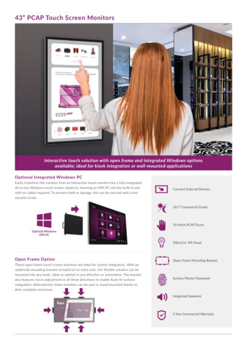
OPTO-TOUCH OTB Series Optical Touch ButtonTwo-Hand ControlTwo-Hand Control is an operator actuating control that initiates a machine cycle through the synchronous use of both buttons andconcurrent actuation during the hazardous portion of the machine cycle. Synchronous use is defined as the actuation of both buttonswithin 500 ms of each other. If one or both buttons are released, an immediate stop command is issued to the machine control andthe hazard ceases at any point in the machine cycle.Alternatively, Two-Hand Trip is similar, but typically initiates a full machine cycle and does not cause a stop or cessation of thehazard if either or both the buttons are released. Two-Hand Trip is typically used on single-cycle or full-revolution machines.In addition to general installation requirements above, Two-Hand Control/Trip can be used for simple machine cycle actuation andmust comply with NFPA 79 and/or ISO 60204-1. If the Two-Hand Control/Trip is also used for safeguarding, additional requirementsmust be complied with and are found in ANSI B11.19, ISO 13851 and other relevant regulations. In either case, the machine (safety)control must also provide the appropriate level of safety performance (risk reduction) as determined by a risk assessment and thefunctions of anti-tiedown and anti-repeat.The level of the safety performance of a Two-Hand Control/Trip system is dependent on the actuating controls (buttons) and thecircuity/logic monitoring those actuating controls (THC modules, Safety Controllers, etc.). Typically, systems incorporating OPTOTOUCH Optical Touch Buttons are limited to Type IIIA or IIIB per ISO 13851. If a Type IIIC system is required, STB Self-CheckingOptical Touch Buttons (datasheet p/n 64136) and an appropriate Two-Hand Control logic module or Safety Controller (for example,AT-FM-10K, SC26/XS26, SC10) can comply with the additional requirements.Anti-tiedown requires the release of both buttons before a subsequent cycle can be re-initiated. This applies after a cycle has beencompleted or if a stop has otherwise occurred. Anti-tiedown function must be designed to ignore false input signals. False signalsinclude (but are not limited to) voltage transients, contact bounce, and EMI or RFI noise. Two-Hand Control logic modules andSafety Controllers with anti-tiedown are available, which include circuitry to minimize the possibility of false actuation.Anti-repeat function causes a stop at the end of the machine cycle and requires release of all actuating controls (for example,,buttons) before another cycle or stroke can be initiated. The anti-repeat function must be incorporated into the machine and/or themachine (safety) control.Other installation considerations include that the actuating controls (for example, buttons) must be arranged far enough apart so thatthe operator cannot operate both actuating controls using one arm or hand. And, both actuating controls must be located far enoughaway from the nearest hazard that the operator cannot reach the hazard with a hand or other body part before the hazardous motionor situation ceases. Installation considerations, including the separation distance (safety distance) and calculations to determine thisdistance are found in ANSI B11.19 or ISO 13851.WARNING: Mount hand controls at a safe distance from moving machine parts Failure to establish and maintain the safety distance (minimum distance) could result in serious injury ordeath. Mount hand controls as determined by the applicable standard. The operator or other non-qualifiedpersons must not be able to relocate the hand controls.WARNING: Use adequate point-of-operation guarding Failure to properly guard hazardous machinery can result in a dangerous condition that could lead toserious injury or death. When properly installed, a two-hand control safety device provides protection only for the hands of themachine operator. It might be necessary to install additional safeguarding, such as safety light curtains,additional two-hand controls, and/or hard guards, to protect all individuals from hazardous machinery.WARNING: Ensure the safety circuit integrity The safety circuit integrity level is affected by the design and installation of the safety devices and themeans of interfacing with those devices. Perform a risk assessment to determine the appropriate safety circuit integrity level or category toensure the expected risk reduction is achieved and all applicable regulations and standards are incompliance (see ANSI B11.0 and ANSI B11.19, ISO 12100 and ISO13849-1 or the applicablestandards).Mounting Hole InformationThe OPTO-TOUCH has a 30 millimeter threaded base which fits directly into astandard mounting hole for an oiltight push button. A lock ring, supplied with eachOPTO-TOUCH, can be used to prevent switch rotation.The mounting hole details shown at the right are used for the OPTO-TOUCH andalso for standard oiltight push buttons and their legend plates. The drawing at thefar right shows how to approximate the keyway using a drill hole.P/N 28436 Rev. N5.0 mm[0.19"]32.8 mm[1.29"]www.bannerengineering.com - Tel: 1 888 373 6767Ø30.0 mm [1.19"]PreferredØ10.0 mm[0.38"]drill12.7 mm[0.50"]Ø30.0 mm [1.19"]Alternative3
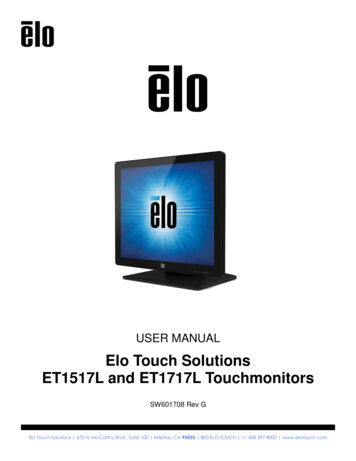
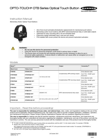
OPTO-TOUCH OTB Series Optical Touch ButtonWiring DiagramsNPN ModelsPNP ellowblackSee SpecificationsN.C. 10–30 V dc–blueLoadAC and AC/DC Modelsbluebrown–10–30 V dc LoadLoadVoltage SpecificationsOTBA5 models: 105 V AC to 130 V ACOTBB5 models: 210 V AC to 250 V ACOTBVR81 models: 20 V AC/DC to 30 V AC/DCNote: For OTBVR81 Models, connection ofDC power is without regard to polarity.CN.O.SpecificationsSupply VoltageSupply voltage varies, depending on the model ordered:105 V AC to 130 V AC210 V AC to 250 V AC (50/60Hz)10 V DC to 30 V DC20 V AC/DC to 30 V AC/DC (at 25 mA, exclusive of load)Supply Protection CircuitryProtected against reverse polarity and transient voltagesOutput Protection100 ms delay on power-up; outputs do not conduct at this timeModels with solid-state outputs are protected against false pulse on powerup and continuous overload or short circuit of outputsOutput Configuration:AC and AC/DC models: All models have SPDT electromechanical relay (oneN.O. contact, one N.C. contact)DC-only models:OTBVN6 models have complementary NPN sinking outputsOTBVP6 models have complementary PNP sourcing outputsIndicator LEDsTwo indicator LEDs. One lights whenever power is applied; the other lightswhenever the switch is activated4Ambient Light Immunity120,000 lux (direct sunlight)EMI/RFI ImmunityHighly resistant to both single and mixed EMI and RFI noise sourcesResponse Time100 ms ON/OFFCableAC and AC/DC quick-disconnect (QD) models require a MBCC-512 5conductor cable, MQDC-4xx 4-conductor cable, MQDC1-5xx 5-conductorcable, or MQDC-4xx 4-conductor cableDC-only quick-disconnect (QD) models require model MBCC-412 4conductor 7/8 in. 16UNF cable, MQDC-4xx 4-conductor cable, or MQDC-4xx4-conductor cableCables are purchased separatelyModels with attached cable (non-QD models): 2 m (6 ft) PVC-jacketed, 22AWG 4- or 5-conductor cableOutput Rating:AC and AC/DC models:Maximum voltage is 250 V AC or 30 V DCMaximum current is 7 amps (resistive load)Minimum load is .05 watts (DC), .05VA (AC)Mechanical life of relay is 50,000,000 operations (minimum)Electrical life of relay is 100,000 operations (minimum) at full resistiveloadTransient suppression recommended when switching inductive loadsDC models:150 mA maximum load (each output)ON-state saturation voltage: less than 1 V at 10 mA; less than 1.5 V at150 mAOFF-state leakage current: less than 1 µAwww.bannerengineering.com - Tel: 1 888 373 6767P/N 28436 Rev. N
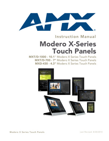
OPTO-TOUCH OTB Series Optical Touch ButtonOperating Temperature–20 C to 50 C (–4 F to 122 F)90% at 50 C maximum relative humidity (non-condensing)Environmental ConsiderationsModels with polysulfone housing): Prolonged exposure to direct outdoorsunlight causes embrittlement of the polysulfone housing. Window glasseffectively filters longer wavelength ultraviolet and provides excellentprotection from sunlight. Contact Banner Engineering regarding outdoorapplications.Models with polycarbonate housing: Avoid prolonged exposure to hotwater and moist high-temperature environments above 66 C (150 F). Avoidaromatic hydrocarbons (such as xylene and toluene), halogenatedhydrocarbons, and strong alkalis. Clean periodically using mild soap solutionand a soft cloth. Avoid strong alkaline materials.ConstructionBlack polysulfone (or red polycarbonate) upper housing and fiber-reinforcedthermoplastic polyester base. Electronics fully epoxy-encapsulated. Totallyencapsulated, non-metallic enclosure. Threaded base has M30 x 1.5external threads and 1/2-in NPSM internal threads. Base requires a 1-3/16-indiameter mounting hole (fits most standard automotive- size jumbo legendplates and oiltight pushbutton holes).Protective cover: Polypropylene copolymerCertifications2399833Environmental RatingNEMA 1, 3, 4, 4X, 12, and 13; IP66Required Overcurrent ProtectionWARNING: Electrical connections must bemade by qualified personnel in accordance withlocal and national electrical codes andregulations.Overcurrent protection is required to be provided by end product applicationper the supplied table.Overcurrent protection may be provided with external fusing or via CurrentLimiting, Class 2 Power Supply.Supply wiring leads 24 AWG shall not be spliced.For additional product support, go to www.bannerengineering.com.Supply Wiring (AWG)Required Overcurrent Protection imensionsFigure 1. OTB with 7/8 in. 16UNF Quick-DisconnectP/N 28436 Rev. Nwww.bannerengineering.com - Tel: 1 888 373 67675
OPTO-TOUCH OTB Series Optical Touch ButtonFigure 2. OTB with M12 Quick-DisconnectAccessoriesCordsets4-Pin 7/8-in Cordsets—Single EndedModelLengthMBCC-4061.83 m (6 ft)MBCC-4123.66 m (12 ft)StyleDimensions52 Typ.Pinout (Female)7/8-16UN-2BStraightMBCC-430ø 25.59.14 m (30 ft)24131 Brown2 White3 Blue4 Black4-Pin Threaded M12 Cordsets—Single EndedModelLengthMQDC-4031 m (3.28 ft)MQDC-4062 m (6.56 ft)MQDC-4155 m (16.4 ft)MQDC-4309 m (29.5 ft)MQDC-45015 m (49.2 ft)6StyleDimensionsPinout (Female)44 Typ.1StraightM12 x 1ø 14.5www.bannerengineering.com - Tel: 1 888 373 67674231 Brown2 White3 Blue4 BlackP/N 28436 Rev. N
OPTO-TOUCH OTB Series Optical Touch Button4-Pin Threaded M12 Cordsets—Single EndedModelMQDC-4100LengthStyleDimensionsPinout (Female)30 m (98.43 ft)5-Pin 7/8-in Cordsets—Single EndedModelLengthMBCC-5061.83 m (6 ft)MBCC-5123.66 m (12 ft)StyleDimensionsPinout (Female)1552 Typ.7/8-16UN-2B243StraightMBCC-530ø 25.59.14 m (30 ft)1 Black2 Blue3 Yellow4 Brown5 White5-Pin Threaded M12 Cordsets—Single EndedModelMQDC1-501.5LengthStyleDimensionsPinout (Female)0.5 m (1.5 ft)MQDC1-5062 m (6.5 ft)MQDC1-5155 m (16.4 ft)354StraightMQDC1-5302144 Typ.1 Brown2 White3 Blue4 Black5 GrayM12 x 1ø 14.59 m (29.5 ft)Mounting BracketsSMB30MM12-ga. stainless steel bracket with curved mounting slots forversatile orientation Clearance for M6 (¼ in)hardware Mounting hole for 30 mm sensor5770C57BAHole center spacing: A 51, A to B 25.4Hole size: A 42.6 x 7, B ø 6.4, C ø 30.1Hole center spacing: A 26.0, A to B 13.0Hole size: A 26.8 x 7.0, B ø 6.5, C ø 31.0P/N 28436 Rev. N67B5829AHole center spacing: A ø 50.8Hole size: A ø 7.0, B ø 30.045SMBAMS30PFlat SMBAMS series bracket 30 mm hole for mountingsensors Articulation slots for 90 rotation 12-ga. 300 series stainless steelSMB30SCSwivel bracket with 30 mm mounting hole for sensor Black reinforced thermoplasticpolyester Stainless steel mounting andswivel locking hardware includedC93ABSMBAMS30RA Right-angle SMBAMS seriesbracket 30 mm hole for mountingsensors Articulation slots for 90 rotation 12-ga. (2.6 mm) cold-rolled steel45C53AB48Hole center spacing: A 26.0, A to B 13.0Hole size: A 26.8 x 7.0, B ø 6.5, C ø 31.0www.bannerengineering.com - Tel: 1 888 373 67677
OPTO-TOUCH OTB Series Optical Touch Button45SMB30ARight-angle bracket with curved slot for versatile orientation Clearance for M6 (¼ in)hardware Mounting hole for 30 mm sensor 12-ga. stainless steelSSA-MBK-EEC1Single 30 mm hole 8 gauge steel, black finish(powder coat) Front surface for customerapplied labelsC61BA69Hole center spacing: A to B 40Hole size: A ø 6.3, B 27.1 x 6.3, C ø 30.5SSA-MBK-EEC2Two 30 mm holes 8 gauge steel, black finish(powder coat) Front surface for customerapplied labels8045BAHole size: A ø 7 , B ø 306017045B80ASSA-MBK-EEC3Three 30 mm holes 8 gauge steel, black finish(powder coat) Front surface for customerapplied labels6025545B80AHole size: A ø 7 , B ø 30Hole size: A ø 7 , B ø 306085SSA-MBK-EEC1-SSSingle 30 mm hole 8 gauge 316 stainless steel Front surface for customerapplied labels608580BA45The SSA-MBK-EECx brackets offer:Horizontal and vertical (post) mounting Interchangeable positions of mounted devices (e.g. OTB/STB/VTB, EStop, K50s)Hole size: A ø 7 , B ø 30Replacement Field CoversField covers are designed to prevent inadvertent activation of optical touch buttons by objects that accidentally block the sensingbeam. Field covers are constructed of rugged polypropylene and are highly resistant to abrasion and to damage by most chemicals.Additional colors are available. Contact Banner Engineering for options.ModelDescriptionOTC-1-BKStandard Black Field CoverØ3151OTCL-1-BK8068Large Black Field Cover92Ø31448www.bannerengineering.com - Tel: 1 888 373 6767148P/N 28436 Rev. N
OPTO-TOUCH OTB Series Optical Touch ButtonBanner Engineering Corp. Limited WarrantyBanner Engineering Corp. warrants its products to be free from defects in material and workmanship for one year following the date of shipment. Banner Engineering Corp. will repair orreplace, free of charge, any product of its manufacture which, at the time it is returned to the factory, is found to have been defective during the warranty period. This warranty does notcover damage or liability for misuse, abuse, or the improper application or installation of the Banner product.THIS LIMITED WARRANTY IS EXCLUSIVE AND IN LIEU OF ALL OTHER WARRANTIES WHETHER EXPRESS OR IMPLIED (INCLUDING, WITHOUT LIMITATION, ANYWARRANTY OF MERCHANTABILITY OR FITNESS FOR A PARTICULAR PURPOSE), AND WHETHER ARISING UNDER COURSE OF PERFORMANCE, COURSE OF DEALING ORTRADE USAGE.This Warranty is exclusive and limited to repair or, at the discretion of Banner Engineering Corp., replacement. IN NO EVENT SHALL BANNER ENGINEERING CORP. BE LIABLE TOBUYER OR ANY OTHER PERSON OR ENTITY FOR ANY EXTRA COSTS, EXPENSES, LOSSES, LOSS OF PROFITS, OR ANY INCIDENTAL, CONSEQUENTIAL OR SPECIALDAMAGES RESULTING FROM ANY PRODUCT DEFECT OR FROM THE USE OR INABILITY TO USE THE PRODUCT, WHETHER ARISING IN CONTRACT OR WARRANTY,STATUTE, TORT, STRICT LIABILITY, NEGLIGENCE, OR OTHERWISE.Banner Engineering Corp. reserves the right to change, modify or improve the design of the product without assuming any obligations or liabilities relating to any product previouslymanufactured by Banner Engineering Corp. Any misuse, abuse, or improper application or installation of this product or use of the product for personal protection applications when theproduct is identified as not intended for such purposes will void the product warranty. Any modifications to this product without prior express approval by Banner Engineering Corp will voidthe product warranties. All specifications published in this document are subject to change; Banner reserves the right to modify product specifications or update documentation at any time.Specifications and product information in English supersede that which is provided in any other language. For the most recent version of any documentation, refer to:www.bannerengineering.com.For patent information, see www.bannerengineering.com/patents. Banner Engineering Corp. All rights reserved
Instruction Manual Momentary Action Optical Touch Buttons Zero-force touch-activated photoelectric replacements for mechanical push buttons Momentary-action touch buttons with SPDT electromechanical relay or solid-state outputs Optimized for easy mounting with a 30 mm threaded base Ergonomic design eliminates hand, wrist and arm .