Transcription
Instruction ManualModero X-SeriesTouch PanelsMXT/D-1000 - 10.1" Modero X Series Touch PanelsMXT/D-700 - 7" Modero X Series Touch PanelsMXD-430 - 4.3" Modero X Series Touch PanelsModero X Series Touch PanelsL a s t R e v is e d : 8 / 2 0 / 2 0 1 4
AMX Limited Warranty and DisclaimerThis Limited Warranty and Disclaimer extends only to products purchased directly from AMX or an AMX Authorized Partner whichinclude AMX Dealers, Distributors, VIP’s or other AMX authorized entity.AMX warrants its products to be free of defects in material and workmanship under normal use for three (3) years from the date ofpurchase, with the following exceptions: Electroluminescent and LCD Control Panels are warranted for three (3) years, except for the display and touch overlay components are warranted for a period of one (1) year. Disk drive mechanisms, pan/tilt heads, power supplies, and MX Series products are warranted for a period of one (1) year. AMX lighting products are guaranteed to switch on and off any load that is properly connected to our lighting products, as longas the AMX lighting products are under warranty. AMX also guarantees the control of dimmable loads that are properly connected to our lighting products. The dimming performance or quality there of is not guaranteed, impart due to the random combinations of dimmers, lamps and ballasts or transformers. AMX software is warranted for a period of ninety (90) days. Batteries and incandescent lamps are not covered under the warranty. AMX AutoPatch Epica, Modula, Modula Series4, Modula CatPro Series and 8Y-3000 product models will be free of defects inmaterials and manufacture at the time of sale and will remain in good working order for a period of three (3) years following thedate of the original sales invoice from AMX. The three-year warranty period will be extended to the life of the product (LimitedLifetime Warranty) if the warranty card is filled out by the dealer and/or end user and returned to AMX so that AMX receives itwithin thirty (30) days of the installation of equipment but no later than six (6) months from original AMX sales invoice date. Thelife of the product extends until five (5) years after AMX ceases manufacturing the product model. The Limited Lifetime Warrantyapplies to products in their original installation only. If a product is moved to a different installation, the Limited Lifetime Warrantywill no longer apply, and the product warranty will instead be the three (3) year Limited Warranty.All products returned to AMX require a Return Material Authorization (RMA) number. The RMA number is obtained from the AMXRMA Department. The RMA number must be clearly marked on the outside of each box. The RMA is valid for a 30-day period. Afterthe 30-day period the RMA will be cancelled. Any shipments received not consistent with the RMA, or after the RMA is cancelled, willbe refused. AMX is not responsible for products returned without a valid RMA number.AMX is not liable for any damages caused by its products or for the failure of its products to perform. This includes any lost profits, lostsavings, incidental damages, or consequential damages. AMX is not liable for any claim made by a third party or by an AMX Authorized Partner for a third party.This Limited Warranty does not apply to (a) any AMX product that has been modified, altered or repaired by an unauthorized agent orimproperly transported, stored, installed, used, or maintained; (b) damage caused by acts of nature, including flood, erosion, or earthquake; (c) damage caused by a sustained low or high voltage situation or by a low or high voltage disturbance, including brownouts,sags, spikes, or power outages; or (d) damage caused by war, vandalism, theft, depletion, or obsolescence.This limitation of liability applies whether damages are sought, or a claim is made, under this warranty or as a tort claim (includingnegligence and strict product liability), a contract claim, or any other claim. This limitation of liability cannot be waived or amended byany person. This limitation of liability will be effective even if AMX or an authorized representative of AMX has been advised of thepossibility of any such damages. This limitation of liability, however, will not apply to claims for personal injury.Some states do not allow a limitation of how long an implied warranty last. Some states do not allow the limitation or exclusion of incidental or consequential damages for consumer products. In such states, the limitation or exclusion of the Limited Warranty may notapply. This Limited Warranty gives the owner specific legal rights. The owner may also have other rights that vary from state to state.The owner is advised to consult applicable state laws for full determination of rights.EXCEPT AS EXPRESSLY SET FORTH IN THIS WARRANTY, AMX MAKES NO OTHER WARRANTIES, EXPRESSED ORIMPLIED, INCLUDING ANY IMPLIED WARRANTIES OF MERCHANTABILITY OR FITNESS FOR A PARTICULAR PURPOSE. AMXEXPRESSLY DISCLAIMS ALL WARRANTIES NOT STATED IN THIS LIMITED WARRANTY. ANY IMPLIED WARRANTIES THATMAY BE IMPOSED BY LAW ARE LIMITED TO THE TERMS OF THIS LIMITED WARRANTY. EXCEPT AS OTHERWISE LIMITEDBY APPLICABLE LAW, AMX RESERVES THE RIGHT TO MODIFY OR DISCONTINUE DESIGNS, SPECIFICATIONS, WARRANTIES, PRICES, AND POLICIES WITHOUT NOTICE.
Table of ContentsTable of ContentsModero X Series Touch Panels (10.1", 7"& 4.3") .1Overview . 1Sleep Button . 2Settings Page. 2Accessing the Settings Page . 2Using the Settings Pages. 2Bluetooth Support . 2NFC Support. 3Picture View. 3Starting Picture View. 4Preview Mode and Normal Mode . 4Picture View Send Command ( PIC). 5Cleaning the Touch Overlay and Case . 5A Note About Wall and Rack Installation. 5Installation Recommendations. 6MXT/D-1000 - 10.1" X Series Panels .7MXT-1000 (Tabletop) . 7MXT-1000 Specifications . 7Touch Panel Aspect Ratio . 9MXT-1000 Installation . 10Connector Locations . 10Power via PoE . 11Ethernet Cable Installation and Modification. 11MXD-1000 (Wall-Mount - Landscape/Portrait) . 12MXD-1000 Specifications . 12Touch Panel Aspect Ratio . 15MXD-1000 Installation. 16Installing the MXD-1000 into a Wall . 16Installing the Backbox. 18Removing the MXD-1000 . 24Removing an MXD-1000 from Its Backbox . 24MXT/D-700 - 7" X Series Panels .27MXT-700 (Tabletop) . 27MXT-700 Specifications . 27Touch Panel Aspect Ratio . 29MXT-700 Installation . 30Connector Locations . 30Power via PoE . 31Ethernet Cable Installation and Modification. 31MXD/T-1000, MXD/T-700 and MXD-430 Modero X Series Touch Panels1
Table of ContentsMXD-700 (Wall-Mount - Landscape/Portrait) . 32MXD-700 Specifications . 32Touch Panel Aspect Ratio . 35MXD-700 Installation. 35Power Via PoE . 35Installing the MXD-700 into a Wall . 35Installing the Backbox. 37Removing the MXD-700 . 41Removing an MXD-700 from Its Backbox . 41MXD-430 4.3” X Series Wall/Flush Mount Touch Panel .43Overview . 43MXD-430 Specifications . 43MXD-430 Installation . 46Power via Power Over Ethernet . 46Installing the MXD-430 into a Wall. 47Installing the Backbox . 47Uninstalling the MXD-430. 51Removing an MXD-430 from Its Backbox. 51Upgrading Firmware .53Overview . 53Downloading Firmware Updates From www.amx.com . 53Upgrading Firmware via USB Flash Drive . 53Load the Firmware on a USB Flash Drive . 53Transfer the Firmware File From the Flash Drive to the Touch Panel. 54Upgrading from Previous Firmware . 55Returning to Factory Default Firmware . 55Upgrading Firmware via NetLinx Studio. 55Transferring the KIT File via NetLinx Studio. 56Appendix: Troubleshooting .57Overview . 57Panel Doesn’t Respond to Touches . 57Panel Isn’t Appearing in the Online Tree Tab. 57Can’t Connect to a NetLinx Master . 57Only One Modero Panel in My System Shows Up . 572MXD/T-1000, MXD/T-700 and MXD-430 Modero X Series Touch Panels
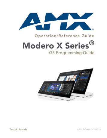
Modero X Series Touch Panels (10.1", 7"& 4.3")Modero X Series Touch Panels (10.1", 7"& 4.3")OverviewThis new generation of G4 touch panels is built for usability offering edge-to-edge capacitive touch glass with multitouch capabilities. It features advanced technology empowering users to operate AV equipment seamlessly, whileproviding the ultimate in audio and video quality. The distinctive appearance will complement even the mostsophisticated meeting facilities and MXD-700-LMXD-430FIG. 1 Modero X Series Touch Panels (10.1", 7" and 4.3")The Modero X Series Touch Panels covered in this manual include:Modero X Series Touch PanelsNameFG#DescriptionPage RefMXT-1000FG5968-0310.1" Modero X Series Tabletoppage 7MXD-1000-PMXD-1000-LPortrait: FG5968-07Landscape: FG5968-1310.1" Modero X Series Wall-Mountpage 12MXT-700FG5968-047" Modero X Series Tabletoppage 27MXD-700-PPortrait: FG5968-08MXD-700-LLandscape: FG5968-147" Modero X Series Wall-Mountpage 32MXD-430FG5968-154.3" Modero X Series Wall/Flush Mountpage 43X Series - No Comm Panels:The X Series - No Comm Panels do not have camera, microphone, or NFC capability. Otherwise, they have all of thefunctionality of the standard Modero X Series panels.MXT-1000-NCFG5968-24MXD-1000-P-NCPortrait: FG5968-25MXD-1000-L-NCLandscape: FG5968-26MXT-700-NCFG5968-27MXD-700-P-NCPortrait: FG5968-28MXD-700-L-NCLandscape: FG5968-29No Comm 10.1" Modero X Series TabletopNo Comm 10.1" Modero X Series Wall Mount PanelsNo Comm 7" Modero X Series TabletopNo Comm 7" Modero X Series Wall-MountMXD/T-1000, MXD/T-700 and MXD-430 Modero X Series Touch Panels1
Modero X Series Touch Panels (10.1", 7"& 4.3")For information on the MXD/T-2000XL and MXD/T-1900L Panoramic X Series touchpanels, refer to the Modero X-Series Panoramic Touch Panels Instruction Manual.Sleep ButtonX Series touch panels are operated using an integral touchscreen, as well as the Sleep button. For tabletop and landscapewall-mount panels, the Sleep button is located on the top center edge of the panel; for portrait panels it is located at theleft center edge.(see FIG. 2).Sleep button(on top panel)Sleep button(on top panel)Sleep button(on left panel)FIG. 2 Sleep Button location - Tabletop, Landscape and Portrait layouts)If the device has gone into its Sleep Mode, a touch of the touchscreen or of the Sleep button will reactivate it.Settings PageUnlike previous AMX touch panels, Modero X Series touch panels no longer have separate Setup and Protected Setuppages. All touch panel settings and functionality are now controlled through one Settings page. The Connection &Networks and Configuration sections are accessible with the correct password.Accessing the Settings PageTo access the Settings page, press and hold the Sleep button on the touch panel for 3 seconds.Alternately, some installation circumstances may require disabling Settings page access through the Sleep button. In thiscase, you may access Settings pages during a bootup of the panel. As the panel boots up, watch for a series of indicatordots to appear on the splash screen (FIG. 3). To access the Settings page, press the bottom right corner of the touchscreenwithin the first three seconds of these dots appearing on the screen.FIG. 3 Indicator dots on the Modero X Series splash screenUsing the Settings PagesWhen opened, the Settings pages appear in the center of the panel display. Please note that many of the pages may belonger than they initially appear. To reach additional functions on a given page, the page itself may be scrolled up anddown to reveal those functions.For detailed information on using the options in the Settings Page to configure the touch panels, refer to the Modero X Series Touch Panels Programming Guide.Bluetooth SupportX Series touch panels allow the use of Bluetooth keyboard and mouse combinations, using HID Profile v1.1.Using a keyboard and mouse with the device requires use of the MXA-BT Bluetooth USB Adapter (FG5968-19).2MXD/T-100, MXD/T-700 and MXD-430 Modero X Series Touch Panels
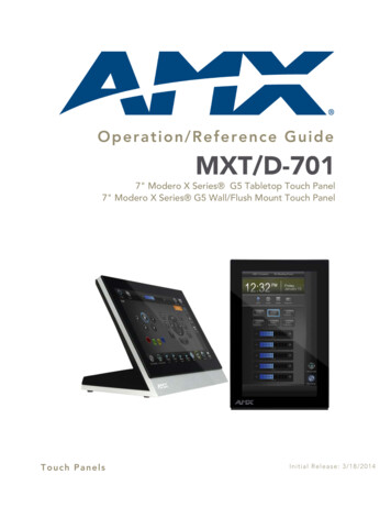
Modero X Series Touch Panels (10.1", 7"& 4.3")NFC SupportX Series touch panels support Near Field Communications (NFC) Technology. NFC technology facilitates makingtransactions, exchanging digital content, and connecting electronic devices with a touch. NFC transmissions are shortrange (from a touch to a few centimeters), working with existing contact-less card technologies and containing built-incapabilities to support secure applications. By using NFC technology, users may receive access to touch panels andtouch panel pages through access badges and other card options.Common Access Card (CAC) Support In MXT/D-2000XL-PANCard TypeCard Unique Identifier (UID) Card DataPersonal Identity Verification (PIV) Cardholder UID156938 byte UIDNot SupportedN/ANot SupportedN/A14443A Non-Gov't 4, 7 or 10 byte UID (1)14443A Gov't4, 7 or 10 byte UID (1)Not Supported (2) Not currently14443B Non-Gov't 4 byte UIDNot SupportedN/A14443B Gov't4 byte UIDNot Supported (2) Not currentlyFeliCaNot SupportedNot SupportedN/A(1) The UID can be a fixed unique number or a random number dynamically generated by the card.(2) Requires contact card reader (not accessible via NFC) The maximum range for the NFC antenna is 0.5" (12.7 mm), but the typical usage range is 0.25" (6.35 mm). The antenna itself is accessible from the front of the panel, 3.25" (82.55 mm) from the left corner of the paneland 0.375" (9.53 mm) from the top edge.When using an NFC device with the X Series panel, align your device’s antenna with the center of the touch panel’santenna (FIG. 4):NFC SensorNFC SensorNFC SensorFIG. 4 NFC antenna location (Tabletop, Landscape and Portrait layouts)To facilitate NFC antenna access, consider adding an icon to the panel’s page(s),pointing to the location of the antenna on the panel.Picture ViewBy connecting a USB drive via one of the device’s USB ports, Picture View allows the Modero X Series panel to accessJPEG images on that drive and display them on the touchscreen. Individual images may be accessed at any time, or theentire collection may be displayed for predetermined times. Picture View may be stopped at any time by removing theUSB drive, and the panel will return to its default display page.The maximum source resolution for Picture View is 1920x1920 pixels.The maximumdisplayed resolution is the same as the screen resolution.MXD/T-1000, MXD/T-700 and MXD-430 Modero X Series Touch Panels3
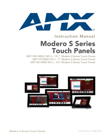
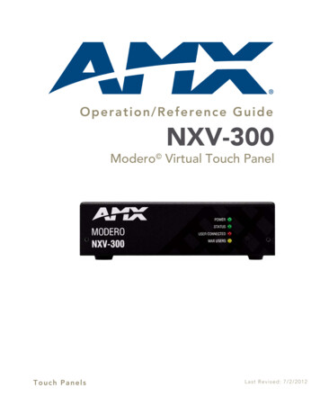
Modero X Series Touch Panels (10.1", 7"& 4.3")Starting Picture View1. Connect a USB drive to the device. Picture View will automatically recognize all available images on the drive andstart displaying them on the touchscreen.2. When the images begin to display, touch any place on the touchscreen to open the configuration popup menu(FIG. 5). If no selection is made, this menu will remain in place for 15 seconds and then disappear. It may beaccessed again by touching anywhere on the touchscreen.Pause/ResumeStopRandom / A-ZCounterPrevious imageTimerNext imageFIG. 5 Picture View Configuration Popup Menu3. On the leftmost amber button, select between Rand (images display at random) and A-Z (images display inalphabetical order based on the name of the file).4. The four gray buttons allow scrolling through saved images and the rate of display: The Previous Image Saved button returns the display to the first image uploaded by Page View. The Stop button stops Page View and returns to the default panel page. The Pause/Resume button allows the display to stop on one particular image. Press it again to resume thedisplay procession. The Next Image Saved button returns the display to the last image uploaded by Page View. If the panel hasnot accessed all of the images available on a USB drive, Page View will display the last one uploaded to date.5. On the rightmost red button, select the number of seconds a selected image will be displayed in Picture View. Thismay be selected between 5, 10, 15, 30, and 60 seconds.6. The counter beneath the buttons displays the number of images currently uploaded by the MST-1001 versus thenumber detected on the USB drive.Preview Mode and Normal ModePicture View has two modes: Preview Mode and Normal Mode. Preview Mode allows the user to configure Picture View.Once a USB drive containing images is inserted into the panel, the images will begin to display. Touching any place onthe display will result in the configuration popup to slide from the bottom of the display.Picture View goes into its Normal Mode when the MST-1001 goes into idle timeout while connected to a USB drive.Normal Mode displays images until the touchscreen is touched, or some other wakeup event is detected. When thedevice goes back into timeout, Normal Mode will return to displaying images until the USB drive is removed from thedevice.4MXD/T-100, MXD/T-700 and MXD-430 Modero X Series Touch Panels
Modero X Series Touch Panels (10.1", 7"& 4.3")Picture View Send Command ( PIC)The PIC Send Command stops either mode of Picture View, or starts Preview Mode. For more information, pleaserefer to the Modero S Series Programming Guide, available at www.amx.com.All images must be in JPEG format. PNG and other image formats cannot be viewedthrough Picture View.Cleaning the Touch Overlay and Case When cleaning the device, do not directly spray the device with cleaning fluid. Instead, spray the cloth andthen apply the cloth to the touch screen. Do NOT use abrasives of any type to clean the device, as abrasives may permanently damage or remove thedevice’s finish.A Note About Wall and Rack InstallationSome products are installed in areas of differing temperature and cooling methodologies. These include productsinstalled in walls, racks, cabinets, etc. Those areas may have different temperatures and/or cooling approaches that mustbe taken into consideration to maintain the product within the specified operating temperature.FIG. 6 shows an AMX device installed in a wall with a filled volume (such as with insulation or concrete), as well aswith a closed volume (such as between studs in an otherwise finished wall). The diagram shows how heat generated bythe device or other devices may have no way to escape, and may build up to levels that may affect device operation.FIG. 6 Heat convection in filled or closed volume, limited or no convectionIn FIG. 7, the diagram displays an AMX device in a typical rack mounting, with full air circulation around the front andback of the device. In this case, the main concern is with heat building up between components, possibly to levels thatmay affect device operation.MXD/T-1000, MXD/T-700 and MXD-430 Modero X Series Touch Panels5
Modero X Series Touch Panels (10.1", 7"& 4.3")FIG. 7 Heat convection in rack-mounted devicesInstallation RecommendationsDuring any installation, a lack of ventilation may produce conditions that may adversely affect the device’s operation. Inthese circumstances, special care must be made to make sure that temperatures within enclosed areas do not exceed thedevice’s maximum rated temperature.While the outside temperature of the device may be at or below its maximumoperating temperature, special care must be taken before and during installation toensure that the maximum operating temperature is not exceeded within wall or rackinstallation spaces.6MXD/T-100, MXD/T-700 and MXD-430 Modero X Series Touch Panels
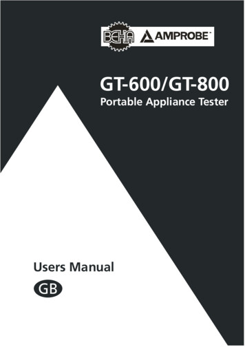
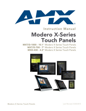
MXT/D-1000 - 10.1" X Series PanelsMXT/D-1000 - 10.1" X Series PanelsMXT-1000 (Tabletop)The MXT-1000 10.1" Modero X Series Tabletop Touch Panel (FG5968-03) features edge-to-edge capacitive touchglass with multi-touch capabilities. It features advanced technology empowering users to operate AV equipmentseamlessly, while providing the ultimate in audio and video quality. The distinctive appearance will complement even themost sophisticated meeting facilities and homes.NFC SensorSleep ButtonSleep ButtonSide ViewUSB Ports (2)FIG. 8 MXT-1000 Touch PanelMXT-1000 SpecificationsMXT-1000 SpecificationsDIMENSIONS (HWD)6 7/8" x 9 7/8" x 4 7/8" (174 mm x 252 mm x 124 mm)WEIGHT3.0 lbs (1.36 Kg)POWER CONSUMPTION Full-On: 8 W Standby: 3.2 W Shutdown: 1 W Start-Up Inrush Current: Not applicable due to PoE standardEXTERNAL POWERSUPPLY REQUIREDOptimal performance requires use of one of the following AMX PoE power supplies (notincluded): PS-POE-AF-TC, PoE Injector, 802.3AF Compliant (FG423-83) NXA-ENET8-2POE, Gigabit PoE Ethernet Switch (FG2178-63)CERTIFICATIONS UL 60950-1 FCC Part 15 Class B C-Tick CISPR 22 Class B CE EN 55022, EN 55024 and EN 60950-1 IEC 60950-1 IC IEC/EN-60950 RoHS/WEEE compliantMXD/T-1000, MXD/T-700 and MXD-430 Modero X Series Touch Panels7
MXT/D-1000 - 10.1" X Series PanelsMXT-1000 Specifications (Cont.)TOUCH SCREEN DISPLAY Display Type: TFT Active Matrix Color LCD with In-plane Switching Technology (IPS) Display Size (WH): 9.9" x 6.7" (252 mm x 170 mm), 12.0" (304 mm) diagonal Viewable Area (WH): 8.5" x 5.3" (217mm x 136mm), 10.1" (257mm) diagonal Resolution (WH): 1280x800 Aspect Ratio (WH): 16:9 Brightness: 400 cd/m2 Contrast Ratio: 700:1 Color Depth: 264K colors Illumination: LED Touch Overlay: Projected capacitive, multi-touch support, 3 simultaneous maxVIEWING ANGLE Vertical: 89 Horizontal: 89 MEMORY SDRAM: 512 MB Flash: 4 GB Maximum Project Size: 2.4 GB flash available to userCOMMUNICATIONS Ethernet: 10/100 Auto MDI-X port, RJ-45 connector. Supported IP and IP-basedprotocols: UCP, TCP, ICMP, ICSP, IGMP, DHCP, Telnet, FTP, DNS, RFB (for VNC),HTTP USB:(2) USB host 2.0, Type A ports (1 with limited physical access requiring right angleconnection): Firmware upgrade, touch panel file transfer, JPEG image viewer, HIDperipherals, USB audio output for headsets(1) Micro-USB device port: video output from on-board camera (landscape touchpanel only), USB audio from on-board microphone to host device Near Field Communication (NFC): Supports standards ISO/IEC 15693, ISO/IEC14443A, ISO/IEC 14443B; Unique Identifier (UID), typ range .25", max .5" Bluetooth:Mouse/Keyboard: HID Profile v1.1, requires MXA-BT Bluetooth Adapter (FG596819)Handset: Hands Free Profile v1.5, Headset Profile v1.2, requires MXA-BT BluetoothAdapter (FG5968-19) and MXA-HST Bluetooth Handset (FG5968-17)VIDEO Supported Video Codecs:MPEG2-TS: MPEG-2 Main Profile @High Level up to 720p at 25 fps (decode only)MPEG-2-TS: H.264 High Profile @Layer 4, AAC-LC up to 720p at 25 fps(encode/decode)MJPEG up to 720p at 25 fps (decode only) Supported Video Transport Streams: MPEG-TS for MPEG-2 and H.264, HTTP forMJPEG Max Number of Active Video Streams: One decode plus one encode Video Output: Camera video output: H.264, up to 720p@25 fps via Micro-USB portonly (controlled by host device) Video Conferencing: Panel-to-panel and video chatAUDIO Microphone: -42 dB 3 dB sensitivity FET microphone Speakers: 4 ohm, 2 Watt, 300 Hz cutoff frequency Supported Audio Codecs:MP2 Layer I and II, MP3 (8 kHz, 11.025 kHz, 12 kHz, 16 kHz, 22.05 kHz, 24 kHz, 32kHz, 44.1 kHz, 48 kHz)AAC-LC (8 kHz, 96 kHz)G.711 with µLaw (VoIP encode/decode at 8 kHz) Audio Output: USB Audio out USB port (head/hand set support) File Formats: WAV, MP3 (as part of touch panel file only - no USB storage) Intercom: Full Duplex VoIP, SIP v2.0 (supported with AMX-CSG)8MXD/T-1000, MXD/T-700 and MXD-430 Modero X Series Touch Panels
MXT/D-1000 - 10.1" X Series PanelsMXT-1000 Specifications (Cont.)GRAPHICS ENGINEAMX G4: G4 enhanced feature set supporting multi-touch and gestures, scrolling,transitions - See TPD4 Operations Guide for more informationEMBEDDED APPLICATIONS Remote Management: VNC Server, G4 Web Control, AMX Resource ManagementSuite Video Conferencing: Panel-to-panel and video chat Audio Conferencing: Audio (Full Duplex Intercom)FRONT PANELCOMPONEN
If the device has gone into its Sleep Mode, a touch of the touchscreen or of the Sleep button will reactivate it. Settings Page Unlike previous AMX touch panels, Modero X Series touch panels no longer have separate Setup and Protected Setup pages. All touch panel settings and functionality are now controlled through one Settings page.