Transcription
TOSHIBAUNINTERRUPTIBLE POWER SYSTEMTHREE-PHASE 15/25/30/50 kVA UPS4200FA CT/XTUser’s ManualDocument Number: 53878-006Date: September 2007
TOSHIBA4200FA CT/XTTHREE-PHASE 15/25/30/50 kVAUNINTERRUPTIBLE POWER SYSTEMCT-Internal BatteriesXT- External Batteries or External TransformerUSER’S MANUALFOR 3F500F#MBNT42#3#500##MXNTOSHIBA INTERNATIONAL CORPORATIONINDUSTRIAL DIVISION13131 West Little York RoadHouston, TX 77041-9990
TOSHIBAIMPORTANT NOTICEThe Instructions contained in this manual are not intended to cover all ofthe details or variations in equipment or to provide for every possiblecontingency to be met in connection with installation, operation, ormaintenance. Should further information be required or should particularproblems arise which are not covered sufficiently the matter should bereferred to the local TOSHIBA sales office.The contents of this instruction manual shall not become a part of or modifyany prior or existing equipment, commitment, or relationship. The salescontract contains the entire obligation of TOSHIBA INTERNATIONALCORPORATION. The warranty contained in the contract between theparties is the sole warranty of TOSHIBA, and any statements containedherein do not create new warranties or modify the existing warranty.Any Electrical or mechanical modifications to this equipmentwithout prior written consent of the TOSHIBA will void allwarranties and may void UL/CUL listing. Unauthorizedmodifications may also result in equipment damage, personalinjury, or loss of life.UNINTERRUPTIBLE POWER SYSTEMIf additional information or technical assistance is required call TOSHIBACustomer Support Center toll free at 1- 877-876-8773, or write to: ToshibaInternational Corporation, 13131 West Little York Road, Houston, TX 770419990 Attn: UPS Product Manager.Please complete the following information for your records. Unless otherwisespecified on the warranty card, the warranty period for the UPS or UPS part is36 months from the shipment date (see bill of lading).Unless otherwise specified on the warranty card, the warranty period for aUPS battery is 24 months from the shipment date (see bill of lading).Keep this manual with the UPS equipment.Job Number:Model Number:Serial Number:Application:Shipping Date:Date of Installation:Inspected By:4200FA CT/XT User’s Manual2
TOSHIBATABLE OF CONTENTSIMPORTANT NOTICE. 2TABLE OF CONTENTS. 3Purpose and Scope of Manual . 5Contacting TOSHIBA Customer Support Center . 5GENERAL SAFETY INSTRUCTIONS. 6EQUIPMENT WARNING LABELS . 7IMPORTANT SAFETY INSTRUCTIONS . 101.0 Product Description. 141.11.21.31.42.0Theory of Operation . 14Application and Use . 14Power Backup . 14Power Conditioning . 14Unpacking/Inspection/Storage/Disposal . 152.12.22.32.32.42.53.0Unpacking the new UPS equipment 15/25/30 kVA:. 15Unpacking the new UPS equipment 50 kVA:. 16Inspection of the new UPS equipment. 16Inspection of the new UPS equipment. 17Storage of UPS equipment . 17Disposal. 17Installation Precautions. 183.13.23.34.0Equipment Placement . 18System Preparation (Pre-Power) . 19Operating Precautions . 19UPS Connections . .4.14.54.5.14.5.24.5.35.05.15.25.35.45.55.6Power Connections . 20Power Connections 15/25/30 kVA with Internal Batteries . 20Power Connections 15/25/30 kVA with Internal Transformer . 21Recommended Wire Size and Torque Requirements. 22Power Connection Cable Routing and Conduit Placement 15/25/30 kVA. 23Control Circuit and External Battery Interface Connections 15/25/30 kvA . 24Recommended Wire Size and Torque Requirements. 24Power Connections 50 kVA . 25Recommended Wire Size and Torque Requirements For UPS Input and Output Terminals. 26Power Connection Cable Routing and Conduit Placement 50 kVA. 27Control Circuit and External Interface Connections 50 kVA . 28Recommended Wire Size and Torque Requirements . 28Communication Interface . 29Remote Contact . 29RS-232C. 30UPS Shutdown (via RS-232C) . 30Specifications. 314200FA 15 / 25 kVA @ 208 VAC Input/ 208 VAC Output w/Internal Batteries . 314200FA 15/25 kVA w/Internal Transformer. 324200FA 30 kVA @ 208 VAC Input/ 208 VAC Output w/Internal Batteries . 334200FA 30 kVA w/Internal Transformer. 344200FA 50kVA @ 208 VAC Input/ 208 VAC Output w/Internal Batteries . 354200FA 50kVA w/Internal Transformer. 364200FA CT/XT User’s Manual3
TOSHIBA6.0Operating the UPS . 376.1 AC Input Mode (Normal Operation). 376.2 Bypass Mode. 386.4 Battery Backup Mode . 396.5Battery Backup Time and Discharge Process . 406.6Battery Low Voltage Tolerances . 406.7Battery Recharging. 416.8Front Panel Layout (All Units) . 426.9EPO (Emergency Power Off) Function . 426.10Audible Alarm Functions . 436.11LED (Light Emitting Diode) Functions . 436.11.1 LED (Light Emitting Diode) System Status . 446.12LCD (Liquid Crystal Display) Functions . 446.12.1 Line-1 System Messages. 446.12.2 Line-2 System Fault Messages. 456.12.3 Line-3 System Messages. 456.12.4 Line-4 System Messages. 456.13Initial Battery Charge. 466.14Start-up Procedure . 476.15Shutdown Procedure. 486.16Maintenance Bypass Procedure . 486.17Keypad Overview . 506.18Key Functions. 516.18.1 MONI . 516.18.2 IN . 516.18.3 OUT. 516.18.4 BATT Key . 526.18.5 MENU, F1, ENTER, UP, & DOWN Keys . 526.18.6 BATT TEST Key. 526.18.7 BUZZ STOP Key . 536.18.8 RESET Key . 536.19Menu Data Screens . 546.19.1 Settings for Calendar and Clock . 546.19.2 Adjusting the Buzzer Volume . 546.19.3 Settings for Display Duration. 546.19.4 Run Switch Select . 556.19.5 Serial Com Station Address . 556.19.6 Output Voltage Adjustment . 566.19.7 Charge Mode Select . 566.19.8 Reset to Default Settings . 576.20Overload Operation. 576.21Backup History and Fault History. 587.07.17.28.08.18.28.39.09.29.3UPS Protection System . 60System Protection Features. 60System Protection Functions . 60Start-up/Scheduled Maintenance/Part Replacement. 61Start-up. 61Preventive Maintenance. 61Parts Replacement. 62External Dimensions / Shipping Dimensions / Weights. 639.1 External Dimensions 15/25/30 kVA . 63External Dimensions 50kVA. 64Shipping Dimensions and Weights . 654200FA CT/XT User’s Manual4
TOSHIBAPurpose and Scope of ManualThis manual provides information on how to safely install, operate, and maintain your TOSHIBA powerelectronics product. This manual includes a section on General Safety Instructions that describes thewarning labels and symbols that are used throughout the manual. Read the manual completely beforeinstalling, operating, or performing maintenance on this equipment.This manual and the accompanying drawings should be considered a permanent part of the equipment andshould be readily available for reference and review. Dimensions shown in the manual are in metric and/orthe English equivalent.TOSHIBA reserves the right, without prior notice, to update information, make product changes, or todiscontinue any product or service identified in this publication.TOSHIBA is a registered trademark of TOSHIBA INTERNATIONAL CORPORATION. All other product ortrade references appearing in this manual are registered trademarks of their respective owners.TOSHIBA shall not be liable for technical or editorial omissions or mistakes in this manual. Norshall it be liable for incidental or consequential damages resulting from the use of informationcontained in this manual.This manual is copyrighted. No part of this manual may be photocopied or reproduced in any form withoutthe prior written consent of TOSHIBA INTERNATIONAL CORPORATION. Copyright 2007 TOSHIBA INTERNATIONAL CORPORATION.All rights reserved.Printed in the U.S.A.Contacting TOSHIBA Customer Support CenterThe TOSHIBA Customer Support Center can be contacted to obtain help in resolving any UninterruptiblePower System problem that you may experience or to provide application information.The center is open from 8 a.m. to 5 p.m. (CST), Monday through Friday. The Support Center’s toll freenumber in USA is (877) 867-8773.You may contact TOSHIBA by writing to:TOSHIBA INTERNATIONAL CORPORATION.INDUSTRIAL DIVISION13131 West Little York Rd.Houston, TX 77041-9990Attn: UPS Product Manager4200FA CT/XT User’s Manual5
TOSHIBAGENERAL SAFETY INSTRUCTIONSDO NOT attempt to install, operate, maintain or dispose of this equipment until you have read andunderstood all of the product safety information and directions that are contained in this manual.Safety Alert SymbolThe Safety Alert Symbol indicates that a potential personal injury hazard exists. Thesymbol is comprised of an equilateral triangle enclosing an exclamation mark.Signal WordsListed below are the signal words that are used throughout this manual followed by their descriptions andassociated symbols. When the words DANGER, WARNING and ATTENTION are used in this manual theywill be followed by important safety information that must be carefully adhered to.Warnings in this manual may appear in any of the following ways:1)Danger warning The danger symbol is an exclamation mark enclosed in a triangle, whichprecedes the word “DANGER.” The Danger warning symbol is used to indicate situations,locations, and conditions that exist and will cause serious injury or death.DANGER2)Caution warning The caution symbol is an exclamation mark enclosed in a triangle, whichprecedes the word “CAUTION.” The Caution warning symbol is used to indicate situations andconditions that can cause operator injury and/or equipment damage.CAUTION3)Attention warning The attention warning symbol is an exclamation mark enclosed in atriangle which precedes the word “ATTENTION.” The Attention warning symbol is used toindicate situations and conditions that can cause operator injury and/or equipment damage.ATTENTIONOther warning symbols may appear along with the Danger and Caution symbol and are used to specifyspecial hazards. These warnings describe particular areas where special care and/or procedures arerequired in order to prevent serious injury and possible death.1)Electrical warning The electrical warning symbol is a lighting bolt enclosed in a triangle. TheElectrical warning symbol is used to indicate high voltage locations and conditions that maycause serious injury or death if the proper precautions are not observed.2)Explosion warning The explosion warning symbol is an explosion image enclosed in atriangle. The Explosion warning symbol is used to indicate locations and conditions wheremolten exploding parts that may cause serious injury or death if the proper precautions are notobserved.4200FA CT/XT User’s Manual6
TOSHIBAEQUIPMENT WARNING LABELSDO NOT attempt to install, operate, maintain or dispose of this equipment until you have read andunderstood all of the product warnings and user directions that are contained in this instruction manual.Shown below are examples of warning labels that may be found attached to the equipment. DO NOTremove or cover any of the labels. If the labels are damaged or if additional labels are required, contactyour TOSHIBA representative for additional labels.The following are examples of the warning labels that may be found on the equipment. The labels are thereto provide useful information or to indicate an imminently hazardous situation that may result in seriousinjury, severe property and equipment damage, or death if the instructions are not followed.4200FA CT/XT User’s Manual7
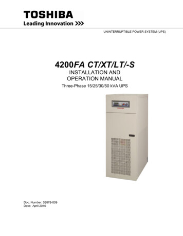
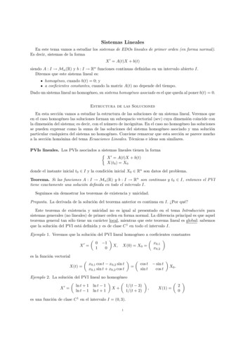
TOSHIBADANGERRISK OF ELECTRIC SHOCKCapacitors stay charged after powerhas been shut off.Accidental contact with live parts cancause personal injury and death.Turn off and lock out all power sources.Wait at least five (5) minutes for powerto dissipate then check voltage beforeservicing.39561DANGERHAZARDOUS VOLTAGESHazardous voltages are used in the operationof this equipment and could cause severe personalinjury or loss of life.The following precautions should be observed toreduce the risk of injury or death.Only qualified technicians familiar with this equipment and theinformation supplied with it should be permitted to install andoperate this equipment.Installation of electrical equipment must be done inaccordance with National Electrical Code and any other stateor local codes. Proper grounding and conductor sizing mustbe installed for safe operation.During operation, keep all covers in place and cabinetdoors shut.When performing visual inspections and maintenance, ifpossible, be sure the UPS is turned off and the incomingAC feed is turned off and locked out.The UPS and Battery Cabinet will have hazardousvoltages present even after the AC feed is turned off.If it is necessary to make measurements with the poweron, do not touch any electrical connection points. Removeall jewelry from wrists and fingers. Make sure test equipmentis in good, safe operating condition.While servicing, stand on some type of insulation, and besure not to be grounded.Follow the safety instructions given in the equipment manualcarefully and observe all danger, warning and caution notices.403084200FA CT/XT User’s Manual8
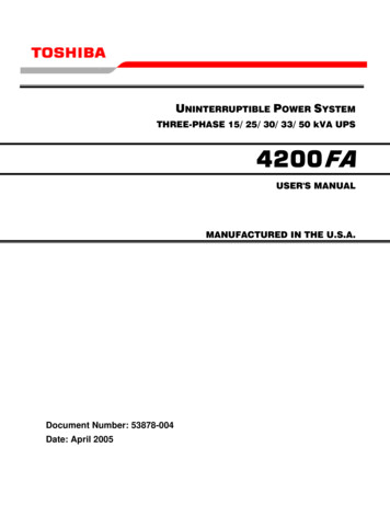
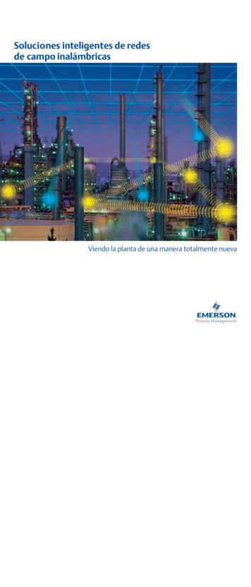
TOSHIBANOTE: This Label for Battery Units Only4200FA CT/XT User’s Manual9
TOSHIBAIMPORTANT SAFETY INSTRUCTIONSSAVE THESE INSTRUCTIONSThis manual contains important instructions that should be followed during the installation, maintenance,and operation of the UPS and its batteries to assure safe and proper operation1. Turn off, lockout, and tagout all power sources before connecting the power wiring to theequipment or when performing maintenance.2. Hardwire type UPS units are not equipped with an over-current protection device, nor do they havean output disconnect for the ac output. Therefore, a user-installed circuit breaker should beprovided between the UPS output and the load input.3. Battery servicing should be performed by a qualified TOSHIBA Representative only.4. Unauthorized personnel should not service batteries.5. Contact your nearest TOSHIBA authorized service center for battery replacement.Qualified Personnel ONLY!Qualified Personnel is one that has the skills and knowledge relating to the construction,installation, operation, and maintenance of the electrical equipment and has received safetytraining on the hazards involved (Refer to the latest edition of NFPA 70E for additional safetyrequirements).Qualified Personnel shall:1. Have read the entire operation manual.2. Be trained and authorized to safely energize, de-energize, ground, lockout and tag circuits andequipment, and clear faults in accordance with established safety practices.3. Be trained in the proper care and use of protective equipment such as safety shoes, rubber gloves,hard hats, safety glasses, face shields, flash clothing, etc., in accordance with established safetypractices.4. Be trained in rendering first aid.5. Be knowledgeable of batteries and the required handling and maintenance precautions.For further information on workplace safety visit www.osha.gov.Refer to the Battery System Manual for details on operating and maintaining the battery units for eachsystem.UPS System’s output is not equipped with an over-current protection device, or an output disconnect forthe AC output; therefore, a circuit breaker should be provided, by the user, between the UPS output andthe critical load input. This minimum current rating for the device should be rated as follows:Rated Output208/120 VAC220/127 VAC240 VAC380/220 VAC480/277 VAC600 VAC15 kVARating240 V, 60 A240 V, 50 A240 V, 50 A480 V, 30 A480 V, 25 A600 V, 20 A4200FA CT/XT User’s Manual25 kVARating240 V, 90 A240 V, 90 A240 V, 80 A480 V, 50 A480 V, 40 A600 V, 35 A30 kVARating240 V, 110 A240 V, 110 A240 V, 90 A480 V, 60 A480 V, 50 A600 V, 40 A50 kVARating240 V, 175 A240 V, 175 A240 V, 175 A480 V, 100 A480 V, 80 A600 V, 70 A10
TOSHIBAThe maximum ambient temperature in which the Uninterruptible Power System (UPS) should be operatedis 104 F (40 C) without batteries, and 89 F (32 C) if the battery cabinet is subject to the same ambienttemperature as the UPS. The nominal battery voltage for all internal battery models is 288 VDC. Thenominal battery voltage for all external battery models is 288 VDC.An Authorized TOSHIBA Representative who is knowledgeable of batteries and the required precautionsshould perform service on the batteries. Keep unauthorized personnel away from batteries.Refer to the Battery System Manual, when scheduling maintenance or battery replacement.Refer to the Battery System Manual when scheduling battery maintenance or battery replacement.Misuse of this equipment could result in injury and equipment damage.In no event will TOSHIBA be responsible or liable for direct,indirect, or consequential damage or injury that may result from the use of this equipment.DANGERCAUTIONDo not dispose of the batteries in a fire. The batteries mayexplode.CAUTIONDo not open or mutilate the batteries. Released electrolyte is toxic andharmful to the eyes and skin.CAUTIONThis unit contains sealed lead acid batteries. An annual preventativemaintenance should be performed by an authorized technician.Failure to do so could result in batteries exploding and emitting gasses.and or flame.CAUTIONDo not open or mutilate the batteries. Released electrolyte is toxic andharmful to the eyes and skin.WARNINGFailure to replace a battery before it becomes exhausted may cause thecase to crack, possibly releasing electrolytes from inside the battery, andresulting in secondary faults such as odor, smoke, and fire.WARNINGOnly personnel knowledgeable of batteries and the required precautionsshould perform installation and servicing of batteries. KeepUnauthorized personnel away from the batteries.WARNINGA qualified service technician must do proper maintenance to the batterysystem of this unit. This is essential for the safety and reliability of yourUPS system. Refer to service manual.DANGERA battery can present a risk of electrical shock and high shortcircuit current.4200FA CT/XT User’s Manual11
TOSHIBAThe following precautions should be observed when working withbatteries.1)2)3)4)5)6)7)8)9)10)11)12)Verify that the “UPS” is off and that the Input Circuit Breaker is in the off position.Remove watches, rings, jewelry, or other metal objects.Use tools with insulated handles to prevent accidental shorts.Wear rubber gloves and boots.Do not lay tools or metal parts on top of batteries.Determine if the battery is grounded. If grounded, remove source of the ground.Contact with any part of a grounded battery can result in an electrical shock.Electrical shock will be reduced if grounds are removed during installation and maintenance.Verify circuit polarities prior to making connections.Disconnect charging source and load prior to connecting or disconnecting terminals.VRLA batteries contain an explosive mixture of hydrogen gas. Do not smoke; create a flame or aspark in the immediate area of the batteries. This includes static electricity.Do not attempt to open the batteries in order to add water or sample the specific gravity of theelectrolyte. The batteries are valve regulated lead acid type and such servicing is not possiblewithout damaging the battery.Use proper lifting means when moving batteries and wear all appropriate safety clothing andequipment.Dispose of lead acid batteries through proper channels in accordance with Local, Stateand Federal EPA Regulations.To be performed by Qualified Personnel only.1) Verify that the UPS is off and that the power cord is disconnected from the power source.2) Remove watches, ring, jewelry, or other metal objects.3) Use tools with insulated handles to prevent inadvertent shorts.4) Wear rubber gloves and boots.5) Do not place tools or any metal parts on top of batteries.6) Determine if the battery is inadvertently grounded. If inadvertently grounded, remove source ofground.Contact with any part of a grounded battery can result in electrical shock.The likelihood of shock will be reduced if such grounds are removed prior to installation ormaintenance.4200FA CT/XT User’s Manual12
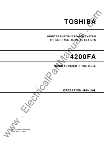
TOSHIBAINSTRUCTIONS IMPORTANTES CONCERNANTLA SÉCURITÉATTENTIONCette notice contient desinstructions importantesconcernant la sécurtéUn battery puet présenter un risque de choc électrique, de brûlurepar transfert d’ énergie.ATTENTIONL’élimination des batteries est règlementèe. Consultar les codeslocaux à cet effetCONSERVER CES INSTRUCTIONS4200FA CT/XT Use
TOSHIBA UNINTERRUPTIBLE POWER SYSTEM THREE-PHASE 15/25/30/50 kVA UPS 4200FA CT/XT User's Manual Document Number: 53878-006 Date: September 2007