Transcription
WHITE PAPERANSI/TIA-606-B
White Paper: TIA-606-BUnderstanding the new updated standard.BACKGROUNDAmerican National Standards Institute (ANSI)Telecommunications Industry Association (TIA)Electrical Industries Alliance (EIA)International Standards Organization (ISO)International Electrotechnical Commission (IEC)ANSI/TIA-606-B is designed to be a generic labeling standard that applies to all types of premises.The standard is backward compatible with the legacy ANSI/TIA/EIA-606-A Addendum 1 and iscompatible with the international standard ISO/IEC TR14763-2-1 identifiers.The original TIA-606-A was designed to identify and record the generaladministration, but did not address the specific needs of the data center designand installation.TIA-606-A was just reaffirmed back in 2007. The TIA-606-A Addendum 1 waspublished in 2008. The addendum reconciled the 606-A with the TIA’s 942data center standard. The current 606-A did not really consider data centersand the 942 did not consider administration. The two concepts came togetherin Addendum 1 to the 606-A. The development of the ANSI/TIA-606-Bcombined the TIA-606-A and the Addendum 1 while harmonizing with therequirements of the ISO/IEC TR14763-2-1.Labeling is a key factor in the installation and maintenance of an efficient andprofessional installation. The 606 standard continues to expand and addresshow and where to identify key components of Information Transport System (ITS).The new 606-B standard not only services the data center, but also commercial,residential, industrial and healthcare facilities. It now establishes guidelinesfor owners, end users, manufacturers, consultants, contractors, designers,installers, and facilities administrators involved in the administration of thetelecommunications infrastructure. In addition, by harmonizing with ISO/IECTR14763-2-1, the updated standard can be implemented internationally. Thenew standard is meant to increase the value of the system owner’s investmentby reducing labor costs associated with maintaining complex infrastructuresystems, which results in extending the useful economic life of the system andby providing effective service to the users in a variety of industries, markets andinternational countries.2
White Paper: TIA-606-BUnderstanding the new updated standard.CHANGES FROM THE LAST REVISION1. Adopts identification scheme specified in TIA-606-A Addendum 1.2. Allows existing TIA-606-A identifier formats to continue to be used wherethey are already in use.NOTE: An identifier is simply the “printed” text that will appear on a label asrelated to the standard.3. Harmonized with ISO/IEC 14763-2-1.4. Creates new identification format for Cabling Subsystem 1 link identifiers(Horizontal links), Cabling Subsystem 2 and 3 links (Backbone cables) as wellas telecommunications outlets, equipment outlets, splices, consolidationpoints and outdoor telecommunication spaces.NOTE: In order to be generic to all types of premises, terminology wasadopted from the TIA-568-C.O. standard in which Cabling Subsystem 1 isnow what was commonly referred to as the “Horizontal Link”. The (1) doesnot mean anything in particular except to differentiate Cabling Subsystem 1links from Cabling Subsystem 2 and 3 links which we commonly referred toas “Cross Connects” or “Backbone” cables. Campus cabling has its owncabling separate from the cabling subsystem 2 and 3 links, which are the2 layers of backbone cabling allowed in premises cabling. The standardallows one level of cross connection in Cabling Subsystem 1 and two levelsof cross connection in Cable Subsystem 2 and 3 cabling. Clause 10.2.1 Thelanguage also makes the standard more generic in that it not only can servicethe data center, but can also service commercial, residential, industrial andmedical facilities.5. Extends administration to all inter-building telecommunications cabling.6. Creates new identifiers for telecommunications outlets, equipmentoutlets, splices, consolidation points and outdoor telecommunication spaces(maintenance holes, pedestals, hand holes, etc.).7. Administers Cabling Subsystem 2 and 3 links by pair groups, correspondingto ports (pairs, strands and grouping identifiers) rather than copper pairs orsingle fibers. See clause 6.1.2.8. Administration of grounding and bonding systems beyond the TMGBand TGB.9. Provides information on implementing automated infrastructuremanagement systems.3
White Paper: TIA-606-BUnderstanding the new updated standard.THE BASICSCLASSESThe basic premise of the TIA-606-B compliant data center implementation isThe standard still breaks out thecriterion by classes of administration.actually very simple and can be broken down using a few common examples.CLASS 1 Locations served by asingle Equipment Room (ER) ThisER is the only TelecommunicationsSpace (TS) administered whereasthere are no TelecommunicationRooms (TRs) and no CablingSubsystem 2 and 3 cabling oroutside plant cabling systems toadminister.A typical patch panel and port identifier might be as follows:CLASS 2 Fulfils the administrationneeds of a single buildingthat are served by multipleTelecommunications Room (TR)swith one or more TR’s within asingle building. This includes all theelements of a class 1 system plusidentifiers for Cabling Subsystem2 and 3 cabling, multi-elementbonding and grounding systemsand fire stopping.CLASS 3 Serves a campusenvironment with multiple buildingsand building pathways, spaces, andoutside plant elements.CLASS 4 Attends the needsof a multi-site (multi-campus)administration.There are slight differences inrequirements depending on whatlevel is administered. In a Class 1system, for example, the floor androom number do not need to beidentified since there is only oneroom to manage. Obviously, as thecomplexity of the system increases,additional identifiers are needed.In Class 3 and 4 systems thereare added requirements, such asbuilding and campus identifiers,outside plant and inter-campuselements such as wide areanetwork connections.1A.AD02-40:021A. Floor 1, room AAD02 The grid location within the data center for a particular rackor cabinet-40 A patch panel located 40 rack units from the bottom of that rackor cabinet:02 A specific port within the patch panel located at AD02-40. (Thiscan also be a range of ports 01-24 as example)Optionally, we can remove the space location to the front of this identifier.If we are on floor 1, space A, and this is the only space, there is no need toinclude that portion on the printed identifier. The actual printed identifiermight look as follows:AD02-40:02Since we are harmonizing to the ISO/IEC TR 14763-2-1, we can optionally adda “ ” sign which specifies that the next portion of the identifier is a locationaspect. The “ ” sign only needs to appear in the records section and not onthe actual label. AD02-40:02An “ ” in front of an identifier specifies a function aspect (Example: XO fortelecommunications outlet).4
White Paper: TIA-606-BUnderstanding the new updated standard.SPACE LABELING1A Floor 1, Space A, which is a alpha-numeric sequence that can be editedto suit the needs of the installation. Example: 3TRA would represent TelecomRoom A on the third floor. An example of an ISO/IEC TR 14763-2-1 compatibleformat is: 3TRA.CABINET AND RACK IDENTIFIERSThe standard recommends the use of GRID COORDINATES to distinguish therack or cabinet in a space. In rooms that have access floor systems, recognitionfor the space shall employ the access floor grid identification scheme usingalpha and numeric characters to mark the X and Y coordinates within the space.‘X’ AUAVAWAXAYAZBABB01020304050607080910111213‘Y’ COORDINATESo, a rack located at grid coordinates AD02, would be marked as ADO2.Typically, the label is placed on the top and bottom, front and rear of the rackor cabinet using machine printed labels.Where grid coordinates are not used, the racks can be marked by row andrack number.5
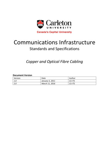
White Paper: TIA-606-BUnderstanding the new updated standard.PATCH PANEL IDENTIFIERSWithin each rack, there will be patch panels. The patch panels shall be labeledwith the identifier of the patch panels at the far end of the cables, if practical.These should be marked using rack units from the bottom of the cabinet.Since the floor/space marking is optional in a Class 2 system, the rack andpanels can be marked by simply combining the grid coordinates of the rackwith the rack units of the panels within that rack. A patch panel 35 rackunits from the bottom of a rack located at grid coordinates AD02 would beidentified as AD02-35.Rack unitposition frombottom ofusable space incabinet or rack45 44Fiber Patch PanelPanel AD02-454342414039Fiber Patch PanelPanel AD02-413837363534Panel AD02-3533323130Panel AD02-3129282726Panel AD02-2725242322Panel AD02-2321201918Panel AD02-1917161514Panel AD02-1513121110Panel AD02-1109080706Panel AD02-070504030201NOTE: The standard also allows the marking of panels and sub-panels usingalpha characters starting with A and excluding “I”, “O” and “Q” as outlined insections 5.1.3.1.1 and 5.1.4.1.6
White Paper: TIA-606-BUnderstanding the new updated standard.PATCH PANEL PORT IDENTIFIERSThe patch panels should be labeled with the identifier of the patch panels at thefar end of the cables, if practical. Each port, the first port or the last port, or thelast of each subpanel shall be labeled. Patch panel labels shall contain the patchpanel identifier. Where space permits, the patch panel also should have labelsto specify the classification at the far end ports using this format. Each panel willhave a series of ports that need to be acknowledged. Thus, a typical patch panel/port identifier on a set of six ports within the patchpanel might be marked as:AD02-35 p 01-06 to AG03-35 p 01-06This can be interpreted as the near end set of six port as being located in a patchpanel 35 rack units from the bottom of rack or cabinet at grid location AD02and these ports are going to the “far-end” set of six ports located in a patchpanel 35 rack units from the bottom of rack or cabinet at grid location AG03.867868869870871872873NOTE: The near end room name and near end patch panel identifier can beure 10 –ure 11urer-ing ex omitted since this information is implicit and inferred from the required cabinet/rack and patch panel labels. See section 5.1.3.1.3.1. The far end room nameof label may also be omitted if the far-end patch panel is in the same room. This meanseld for t that the length of the identifier can be truncated to save space yet keep theformat intuitive to the user.Example:One could shorten the example above to “p 01-06 To AG03-35 p 01-06”Patch panels that support Cabling Subsystems 2 or 3 should indicate the nameof the space; Main Distribution Area (MDA), Intermediate Distribution Area(IDA), Horizontal Distribution Area (HDA) or TR to which the cables run. Section5.1.3.1.3.1.874875876877ure 11 –8781.3.3879880881le foPorts 01-06 to HDA01 AJ17-45 Ports 01-06ure 12 and gure 13In ure 12orts.panelSection 5.1.4.4. All ports on patch panels and all positions on termination blockso wayshall be labeled with the corresponding port number or position number ands subpanoptionally with additional identifier fields as practical. All subpanels shall belabeled with their subpanel identifier. An example of a sub-panel identifier isusually indicated by an alpha character:7
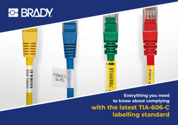
White Paper: TIA-606-BUnderstanding the new updated standard.Ports A1-A6 & B1-B6 to AG10-B Ports 01-12Certain applicationsmay provide electricalpower in additionto data transmissionover balanced twistedpair cables. Visualidentification of portswith power MAYbe accomplishedthrough the use ofthis symbol.Ports A1-A6Ports B1-B6AG10-BPorts 01-12 Sub panel A, ports A1-A6 Sub panel B, ports A1-A6 Sub panel B in rack at grid location AG10 Ports 1 to 12 in sub panel BSPECIALIZED APPLICATIONSThe new standard does address unusual and constantly changing circumstances.As an example from section 5.1.3.1.1, several manufacturers have come outwith cabinets that use zero rack mount space by incorporating vertical rails inthe cabinet to save space. In short, additional patch panels reside on either sideof the cabinet in a vertical position.In this case, how does one identify these vertical patch panels? A simple way tomark the vertical panels is to use rack units combined with an alpha characterfor location within the rack or cabinet. The TIA-606-B now designates anadditional alpha letter indicating the side as A, B, C, D, or F, L, R, B (Front, Left,Right, Back) as examples. This can be used when Rack Units (RU) are designated.The user can then name the horizontal and vertical patch panels by rack unit.The rack unit of the vertical patch panel is determined by the rack unit location,of the height of the top of the vertically mounted patch (by height at the top).A separate alpha designation for Right (R) or Left (L) to distinguish the verticalpatch panels as being either on the left or right side of the cabinet.EXAMPLE: AG09-L35:01-06In this case, the credential is describing a patch panel at 35 rack units fromthe bottom of the rack, on the left side of the cabinet, at grid location AG09,ports 1 to 6.Using pre-terminated copper or fiber solutions, Zero U, high density cabinetscan allow additional ports where you need them and aligns connectivity withthe servers. This allows for moves, adds, and changes without interrupting rackmounted equipment in a fully populated cabinet. This is a new trend in cabinetmanagement to maximize data center real estate and the new TIA-606-Bstandard is flexible enough to allow proper identification of these vertical panels.8
White Paper: TIA-606-BUnderstanding the new updated standard.CABLING SUBSYSTEM 1 LINK / HORIZONTAL LINK IDENTIFIERSThe main focus of the 606-B standard is to be able to track the ITS from the datacenter to the work area. Using the new format, a horizontal link identifier thatterminates at both ends on panels within the same data center would be printedas follows:NEAR END AG09-35:01 / AJ06-35:01FAR END AJ06-35:01 / AG09-35:01If standing at rack location AG09, reading this near end cable identifier willdescribe both the near end and far end locations.AG09 Rack or cabinet at grid location AG09 within the data center- 35 Patch panel located 35 rack units from the bottom in rack AG09:01 Port 01 in patch panel located 35 rack units from the bottom of rack AG09/ Separator for near end/far end location descriptionAJ06 Rack or cabinet at grid location AJ06 within the data center-35 Patch panel located 35 rack units from the bottom in rack AJ06:01 Port 01 in patch panel located 35 rack units from the bottom ofthe rack in AJ06The ISO/IEC TR14763-2-1 identifiers would appear as follows for a CablingSubsystem 1 Link;AG09-35:01 / AJ06-35:01 WThe “W” is the letter code for cables as specified in IEC 81346-2.NOTE: In commercial buildings, industrial premises, data centers and multi-tenantbuildings, each individual telecommunications outlet or equipment outlet shall belabeled with the Cabling Subsystem 1 link identifier. The labeling SHALL appearon the connector, faceplate and Multi User Telecommunications Outlet Assembly(MUTOA) in a way that clearly identifies the individual connector associated withthe particular identifier. Section 5.1.7.3.In sections 5.1.8.1 to 5.1.11.2 when using the Cabling Subsystem 1 link identifiers,it is optional to identify Equipment Outlets (EO’s) and telecommunication outlets(TO’s) by using a two letter code to identify the outlet.XOXCXLXSz Equipment room outlets Consolidation points Zoned Distribution Areas (ZDA) ports Splice where “z” is the appropriate distance along the cable of the splicefrom the termination point in the telecommunications room or HDA.An example of a Cabling Subsystem l link identifier using the option to identifythe outlet might look as follows:AG09-35:01 / AJ06-35:01 XL:5The port on the consolidation point may optionally be identified by a colon “:” andthe port after the XL.Figure 4: Option B is using two MPO/MTP connectors side by side with 1 row of 12array fibers on each connector.9
White Paper: TIA-606-BUnderstanding the new updated standard.GROUNDING AND BONDINGThe standard addresses grounding and bonding beyond the (TelecommunicationsMain Grounding Busbar) TMGB and (Telecommunications Grounding Busbar)TGB with the optional addition of the (Rack Grounding Busbar) RGB, (MeshBonding Network) MBN, (Bonding Conductor for Telecommunications) BCT,(Telecommunications Bonding Backbone) TBB, as well as being able to attachobjects such as an identifier for a cabinet or rack or electrical panel as somecommon examples. See sections 5.1.12 to 5.2.A practical example might be a rack grounding Busbar identifier where you mayhave more than one Rack Grounding Busbar (RGB) in the cabinet rack or wallsegment is shown below.2A RGB12ARGB Floor 2, Room A Rack Grounding Busbar #1The standard also allows the addition of an identifier that identifies an object towhich the bonding conductor is attached. This might include an electrical panel, apathway, building steel, a cable tray or equipment such as a Local Area Network(LAN) switch. Typically this is the TIA-606-B identifier of the equipment. In thisexample, we add the grid location of the rack or cabinet to which the RGB isattached:2A RGB1/AJ052A Floor 2, Room ARGB Rack Grounding Busbar #1AJ05 Rack at grid location AJ05 which is the object attached to the RGB10
White Paper: TIA-606-BUnderstanding the new updated standard.BUILDING CABLING SUBSYSTEM 2 AND 3 CABLE IDENTIFIERSThe backbone cabling is handled very similar to Cabling Subsystem 1 link identifiersexplained earlier in this document. A typical identifier will include the identifier for thespace at one end of the cable, the space terminating the other end of the cable andone or two alpha numeric characters to identify a single pair or port.1A.AJ06-27:01 / 2A.AJ09-27:011AAJ0627:01 Floor 1, Space A Rack or cabinet at grid location AJ06 Patch panel located 27 rack units from the bottom of the frame Port 1For Class 3 and 4 installations, the installer is just adding campus andbuilding identifiers.Example of a backbone cable identifier:A-ENG-1A:AJ06-27:01-06 / B-ADM-1A.AJ09-27:01-06AENGBADM Campus A Engineering Building Campus B Administration BuildingNOTE: Administration of Cabling Subsystem 2 and 3 identifiers is by pair groupsor ports rather than copper pairs or single fibers. Each port or pair on a buildingCabling Subsystem 2 and 3 cable shall have a unique identifier. Individual opticalfibers and balanced pairs are typically color coded rather than individually marked.11
White Paper: TIA-606-BUnderstanding the new updated standard.FIRESTOPPINGThe TIA-606-B legacy format for marking a fire stop would be printed as follows:2-FSL01(6)2-FSL01(6) 2nd Floor First Stop Location Location # 6 hour burn ratingThe comparable format for ISO/IEC 14763-2-1 would be printed as follows:SF02-2A/3A U(3) FSF022A/3A U(3)F Building SF02 Floor 2, space A Located between telecom rooms 2A and 3A Floor 3, space A U following the equal sign specifies the element is a pathway Sleeve 3 Specified the element is a Fire stop locationSPECIAL PURPOSE CABLE MANAGEMENT SOFTWAREThe new ANSI/TIA-606-B standard also covers automated infrastructuremanagement systems which may include technology used to detect and to recordinfrastructure changes (e.g. pre-printed serialized bar codes, human readabletext, RFID chip technology and electrical continuity contacts. There are no specificlabeling requirements and each can be labeled in a variety of ways that suiteach installation, but should contain the records described in the 606-B. Thesespecialized software programs should be able to directly generate the labels or beable to export data to other devices or labeling software that can generate themachine printed labels.Figure 5: Option C is using two MPO/MTP connectors stacked with 1 MPO/MTPconnector on top of the other connector. This drawing shows Receiver on topand Transmitter on the bottom.12
White Paper: TIA-606-BUnderstanding the new updated standard.OUTSIDE PLANT AND PATHWAY IDENTIFIERSThe new standard also addresses outside plant and pathways by identifyinginter-building and outside plant pathways as well as entrance pathway identifiers.As an example, a maintenance hole, handholes, pedestal or outdoor cabinet mightbe identified as follows:LAX1-MH101(37.797413,-122.414925)The Maintenance Hole on campus LAX1 is located at Global Positioning System(GPS) coordinates 37.797413 -122.414925. The use of GPS is optional and couldbe replaced site locations such as site MH12 which would represent MaintenanceHole 12 on campus LAX1. See section 9 under Optional Identifiers ForInfrastructure Elements.LAX1-MH12TypicalApplicationALTERNATE LABEL FORMATS150CCentral OfficeConnectionGreen353CUser Side ofCentral n toPBX, MainframeComputer, LAN,MultiplexerSection 4.6 allows the use of a direct link to an identifier within the records using aprinted label with a short and simple numeric code or a machine readable label suchas an RFID chip or a pre-printed barcode label. So, as example, in the record, theidentifier for a particular port might be: A-ENG-1A:AJ06-27:01-06 / B-ADM-1A.AJ09-27:01-06CablingSubsystem 3WhiteCablingSubsystem nations ofBuilding CablingSubsystem 3Cable ConnectingMC ot ICsTermination ofBuilding CablingSubsystem 2Cable ConnectingIC ot HCsTerminationof CampusInter-buildingCable BetweenBuildingsCablingSubsystem 31Blue291CTerminations ofCabling Subsystem1 Cable In TSsMiscellaneousYellow101CAlarms, Security,or ntOrangeNetworkConnectionPantone#10.2.2 Table 4 ColorsThe actual label might simply be printed with the number 132, (in human readabletext or barcode) but the number 132 is a direct link and cross reference to thedetailed identifier (A-ENG-1A:AJ06-27:01-06 / B-ADM-1A.AJ09-27:01-06) in theactual database. This can reduce the number of characters required to print on thecable or equipment label.COLORSUsing colors is recommended, but not a requirement. Many smaller installers find itcostly to stock and purchase many colors of labels in order to meet a requirementthat might not fit their particular situation. The 606-B is not color dependent andallows the installer to fully identify without requiring the use of a color. If color isused, the installer should use the pantone color scheme as outlined in section10.2.2, table 4.13
White Paper: TIA-606-BUnderstanding the new updated standard.RECORDSMost installers are aware of the cost of installing and maintaining an efficient andcost effective ITS. Labeling is crucial in this area. Yet, there is an aspect that is oftenneglected – record keeping. Maintaining records of your ITS installation is themost valuable part of any labeled configuration. In the standard, you must link arecord for each identifier that is printed on a label. If the records are complete andaccurate and contain the recommended data as outlined in the labeling standard,the customer will have a well documented infrastructure that can be understood andmanaged by anyone responsible for making moves, adds or changes.So, the label is important, but if you do not attach the relevant data to thatidentifier, much of that value is lost. A database can be something as simple asan Excel spreadsheet. Each identifier makes up a row in the spreadsheet and eachelement associated with that identifier is recorded in the columns going acrossthe database.As an example, each Cabling Subsystem 1 link (Horizontal link) record shall includethe following:Location of work area outlet connectorCabling Subsystem 1 link identifier.Outlet connector type (8 position, 110, SC or duplex as example)Cross connect hardware (Patch panel, T568B Cate 53, etc)Cable type (4pr. UTP, Cat 5e, plenum, or 2 strand 62.5/125 multi-mode,FDDI grade, riser)Cable lengthService record of linkIt may also include any other data that the installer or customer feels is pertinentto the installation such a the color code of the outlet connectors, wiring scheme,Multiple User Telecommunications Outlet Assembly (MUTOA) Consolidation Point(CP) or Transition points.(It could be shown in the form of an Excel Spreadsheet like below)Example ofspread-sheetimplementation ofclass 1 administrationsystem: horizontallink records sortedby building roomnumber.HorizontalLinkIdentifierCable TypeBuildingLocationof OutletOutletConnectorTypeColor Codeof OutletConnectorOther OutletConnectors atthis MUTOACPTrans.Point1A-W01Cat 5e PlenumR1118 Pos -A01Cat 5e PlenumR1118 Pos A-B0162.5/125, TwoStrand, PlenumR111SC A-W02Cat 5e PlenumR1128 Pos -A02Cat 5e PlenumR1128 Pos A-B0262.5/125, TwoStrand, PlenumR112SC 4
White Paper: TIA-606-BUnderstanding the new updated standard.If the ITS is not efficient to administer, the cost of any mistakes far outweigh theinitial cost of recording all the data initially at the time of installation. In the longrun, the expense of not recording administration data can be very high. The outlayof testing and tracking cables can be expensive and can result in a backlog ofcables that are abandoned in the plenum in lieu of simply pulling a new cable. Evenan installation that appears intuitively simple, may grow over time and eventuallybecome an unmanageable mess if the ITS is not recorded properly.The TIA-606-B standard is the culmination of years of work by many experts,installers, engineers and customers to make the best system possible. There arestill elements that must be addressed, but it is a standard that is now having globalattention. It is a paradigm that will continue to develop and change the way wethink about administration and labeling.15
White Paper: TIA-606-BUnderstanding the new updated standard.About HellermannTytonHellermannTyton is a global manufacturer of identification, cablemanagement and connectivity solutions for the commercial data,telecommunications, electrical, and industrial markets. HellermannTytonoffers an integrated approach to design, operation, and delivery to optimizeservice and solutions for local and global customers. The company’s engineeredsolutions and innovative products are designed and constructed to meet thestrictest quality standards while delivering reliable implementation at thelowest cost.For more information, call HellermannTyton at 800.537.1512 or visitwww.hellermann.tyton.com for published details.AuthorTodd FriesHellermannTyton North AmericanCorporate Headquarters7930 N. Faulkner Rd, PO Box 245017Milwaukee, WI 53224-9517Phone: (414) 355-1130, (800) 537-1512Fax: (414) 355-7341, (800) 848-9866email: , ISO 9001,and ISO14001 CertifiedThis information contained in the document represents the current view of HellermannTyton with respect to thesubject matter contained herein as of the date of the publication. HellermannTyton makes no commitment tokeep the information presented up to date and the facts in this document are subject to change without notice.As HellermannTyton must respond to the changing market conditions, HellermannTyton cannot guaranteethe accuracy of any information presented after the date of the issuance. This document is presented forinformational purposes only.All rights reserved. No part of these pages, either text or image may be used for any purpose other thanpersonal use. Therefore, reproduction, modification, storage in a retrieval system or retransmission, in any formor by any means, electronic, mechanical or otherwise, for reasons other than personal use, is strictly prohibitedwithout prior written permission.Copyright 2011, All rights reserved. May not be reproduced without the consent of HellermannTyton. HellermannTyton Corporation16
The original TIA-606-A was designed to identify and record the general administration, but did not address the specific needs of the data center design and installation. TIA-606-A was just reaffirmed back in 2007. The TIA-606-A Addendum 1 was published in 2008. The addendum reconciled the 606-A with the TIA's 942 data center standard.