Transcription
Installation InstructionsPanelView 300 Micro Terminals(Catalog Numbers 2711-M3A18L1, 2711-M3A19L1)Inside:English. 3Français . 25Deutsch . 47Español. 69Italiano . 9141061-156-01(A)
2PanelView 300 Micro Terminals41061-156-01(A)
Installation InstructionsEnglishPanelView 300 Micro Terminal(Catalog Numbers 2711-M3A18L1, 2711-M3A19L1)Inside:For More Information. 4European Communities (EC) Directive Compliance . 4Hazardous Locations . 5Wiring and Safety Guidelines. 6Mounting the Terminal. 6Connecting DC Power . 10Using the Communications Port . 13Accessing Configuration Mode . 18Resetting the Terminal. 18Comm and Fault Indicators . 19Troubleshooting and Maintenance . 20Accessories . 22Specifications . 2341061-156-01(A)
4PanelView 300 Micro TerminalFor More InformationForRefer toMore detailed information on the 300 Micro and Standard PanelViewthe other Standard PanelView terminals.Terminals User ManualRefer to2711-UM014A-EN-PIf you would like a publication, you can: download a free electronic version from the PanelBuilder32 installation CD download a free electronic version from the internet:www.ab.com/manuals/eoi or www.theautomationbookstore.comTo purchase a publication: visit the www.theautomationbookstore.com and place your order contact your local distributor or Rockwell Automation RepresentativeEuropean Communities (EC) DirectiveComplianceThis product has the CE mark and is approved for installation within theEuropean Union and EEA regions. It has been designed and tested to meet thefollowing directives.EMC DirectiveThis product is tested to meet the Council Directive 89/336/EC ElectromagneticCompatibility (EMC) by applying the following standards: EN 50081-2 EMC - Generic Emission Standard, Part 2 - IndustrialEnvironment EN 61000-6-2 EMC - Generic Standard, Immunity for IndustrialEnvironments.This product is intended for use in an industrial environment.41061-156-01(A)
PanelView 300 Micro Terminal5Hazardous LocationsThis equipment is suitable for use in Class 1, Division 2, Groups A, B, C, D ornon-hazardous locations only. The following DANGER statement applies to usein hazardous locations.DANGER!Explosion Hazard Substitution of components may impair suitability for ClassI, Division 2. Do not disconnect equipment unless power has beenswitched off and area is known to be non-hazardous. Do not connect or disconnect components unless power hasbeen switched off. All wiring must comply with N.E.C. article 501-4(b). Peripheral equipment must be suitable for the location it isused in.Use only the following communication cables in Class 1, Division 2, HazardousLocations.Environmental ClassificationCommunication Cable1761-CBL-PM01, Series C1761-CBL-HM02, Series C1761-CBL-AM00, Series CClass I, Division 2, Hazardous Locations1761-CBL-AP00, Series C2711-CBL-PM05, Series C2711-CBL-HM05, Series C2711-CBL-PM10, Series C2711-CBL-HM10, Series C41061-156-01(A)
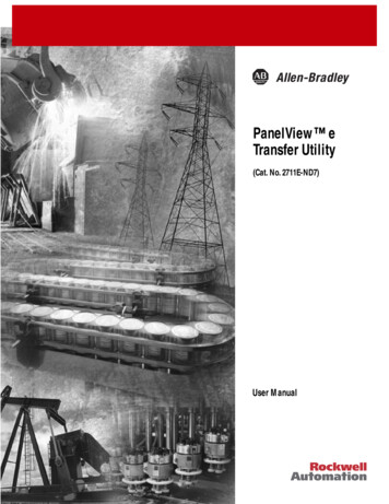
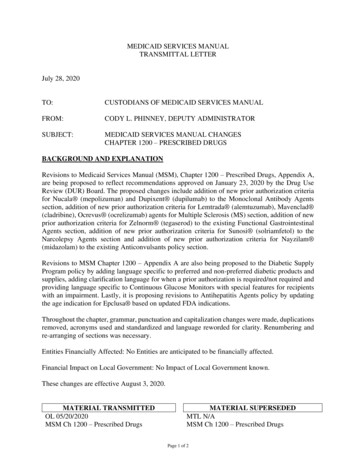
6PanelView 300 Micro TerminalWiring and Safety GuidelinesInstall the PanelView 300 Micro terminal using publication 70E, ElectricalSafety Requirements for Employee Workplaces. In addition to the NFPA generalguidelines, follow these recommendations: Route incoming power to the PanelView 300 Micro by a separate path fromthe communication cable. Where power and communication lines must cross, they should cross at rightangles. Communication lines can be installed in the same conduit as low levelDC I/O lines (less than 10 Volts). Grounding minimizes noise from Electromagnetic Interference (EMI) and is asafety measure in electrical installations. To avoid EMI, shield and groundcables appropriately.A source for grounding recommendations is the National Electrical Codepublished by the National Fire Protection Association of Boston.Mounting the TerminalEnclosuresMount the PanelView 300 Micro terminal in a panel or enclosure to protect theinternal circuitry. The terminal meets NEMA 12/13 and 4X (indoor use) ratingsonly when properly mounted in a panel or enclosure with the equivalent rating.Allow enough space within the enclosure for adequate ventilation. Consider heatproduced by other devices in the enclosure. The ambient temperature around thePanelView 300 Micro must be between 0 and 55 C (32 and 131 F).Make provisions for accessing the side panel of the terminal for wiring,maintenance and troubleshooting.Mounting Dimensions111 mm(4.38 in.)35 mm(1.39 in.)133 mm(5.23 in.)41061-156-01(A)48 mm(1.87 in.)
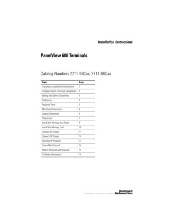
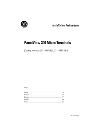
PanelView 300 Micro Terminal7Cutout DimensionsUse the full size template shipped with the PV300 Micro to mark the cutoutdimensions. The figure below shows a reduced scale cutout. A full scale templateis also available inside the back cover of this document.4.42 in. (112 mm)4.0 in. (102 mm)0.178 in. (4.5 mm)Diameter3.62 in.(92 mm)2.12 in.(54 mm)ClearancesAllow 51 mm (2.0 inches) of space on all sides of the terminal for adequateventilation and maintenance.2.0 in. (51 mm)2.0 in. (51 mm)41061-156-01(A)
8PanelView 300 Micro TerminalInstalling Terminal in PanelOther than the tools required to make the panel cutout, the tools required forinstallation are: 7 mm (M4) deep well socket wrench or nut driver small slotted screwdriver torque wrench (in. / lbs.)To install the PV300 Micro in a panel:ATTENTION! Disconnect all electrical power from the panel beforemaking cutout. Make sure area around the panel cutout is clear. Take precautions so that metal cuttings do not enter anycomponents already installed in panel. Failure to follow this warning may result in personal injuryor damage to the panel components.1. Cut an opening in the panel using the panel cutout provided with the terminal.Remove sharp edges or burrs.2. Make sure the sealing gasket is properly positioned on the terminal (as shownbelow). This gasket forms a compression type seal. Do not use sealingcompounds.Sealing Gasket3. Place the terminal in the panel cutout.41061-156-01(A)
PanelView 300 Micro Terminal94. Install the 4 self-locking nuts, hand tight.Self-Locking Nuts(4 used, 6 provided)5. Alternately tighten the self-locking nuts until the terminal is held firmlyagainst the panel. Tighten the nuts to a torque of 10 inch-pounds. Do notovertighten.ATTENTION!Mounting nuts must be tightened to a torque of 10inch-pounds to provide a proper seal and to preventpotential damage to the terminal. Allen-Bradley assumes noresponsibility for water or chemical damage to the terminalor other equipment within the enclosure because ofimproper installation.41061-156-01(A)
10PanelView 300 Micro TerminalConnecting DC PowerThe PV300 Micro terminal connects to a 24V dc power source. The table belowshows the electrical ratings for the DC versions of the terminals. Electroniccircuitry and an internal fuse protect the terminals from reverse polarity andover-voltage conditions.Terminal TypeSupply VoltagePower ConsumptionPV300 Micro11 to 30V dc(24V dc nominal)2.5 Watts maximum(0.105 Amps @24V dc)PV300 Micro terminal is designed for safe use when installed in a suitably ratedNEMA Type 12, 13, 4X (indoor use only), IP54 or IP65 enclosure.ATTENTION! Do not connect the PanelView terminal to an AC powersource. Connecting to an AC power source will damage theterminal. Use only a Safety Extra Low-Voltage (SELV) power supplywith an output rated between 11 - 30V dc as a power sourcefor the PanelView 300 Micro. A SELV power supply doesnot exceed 42.4V dc.The input power terminal block on the PanelView 300 Micro is removable andsupports the following wiring types.Wire TypeWire Size (2-wire maximum per terminal)Solid#16 to #22 AWGStranded#18 to #22 AWG41061-156-01(A)
PanelView 300 Micro Terminal11To connect DC power to the PanelView 300 Micro terminal:1. Secure the DC power wires to the screw terminal block.2. Secure the Functional Earth Ground wire to the screw terminal block.DANGER!Explosion Hazard Substitution of components may impair suitability for ClassI, Division 2. Do not disconnect equipment unless power has beenswitched off and area is known to be non-hazardous. Do not connect or disconnect components unless power hasbeen switched off. All wiring must comply with N.E.C. article 501-4(b).3. Apply power (24V dc nominal) to the terminal. DC Positive- DC NegativeFunctional Earth GroundRemoving and Installing the Power Terminal BlockYou can remove and re-install the power terminal block for ease of installation,wiring and maintenance. The terminal block is pre-installed when shipped.Additional terminal blocks (quantity of 10) are available by ordering CatalogNumber 2711-TBDC.To remove the DC power terminal block:1. Disconnect all electrical power from the panel. See Explosion Hazard Warningabove.2. Insert tip of small flat-blade screw driver into DC power terminal access slot.41061-156-01(A)
12PanelView 300 Micro TerminalInsert tip of screw driver here.3. Gently push the blade of the screw driver away from the terminal block torelease locking mechanism.4. Remove DC power terminal block.To re-install the DC power terminal blockNote: Install the terminal block with or without the power wires connected.1. Disconnect all electrical power from the panel prior to installation. SeeExplosion Hazard Warning on previous page.2. Position the terminal block at a 45 angle to the base surface and place loweredge of the wire connection side into the base.3. Gently push the top of the terminal block back to a vertical position to snap inthe locking tab.Press terminal blockbase in first withblock leaning outwardPush top back tovertical positionto lock-in.41061-156-01(A)
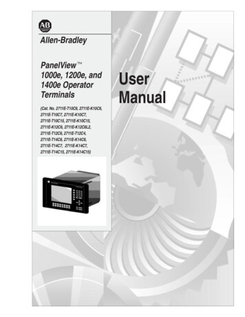
PanelView 300 Micro Terminal13Using the Communications PortThe PanelView 300 Micro terminal is available in 2 versions.Catalog NumberCommunication PortCommunication 85Both versions have an identical RS-232 communications port with a MicroLogix8-pin mini-DIN style connector. The only difference is the protocol firmware(DF1 or DH485) pre-loaded at the factory. Both versions of the protocolfirmware are supplied with the PanelBuilder32 software. You can change theprotocol by downloading the firmware to the terminal using the WindowsPanelView MotherBoard Firmware Download Utility (WinMBFWDL) utility.This utility is included with the PanelBuilder32 software.21534RS-2328-pin mini-DINconnectorPort is used for bothcommunications with a controllerand to transfer application files.678Pin # Signal1NC (No Connection)2GND3RTS4RXD5NC (No Connection)6CTS7TXD8GNDThe following table lists the communication parameters supported by each of theprotocols on the RS-232 communications port.Communication LinkCommunication ParametersRS-232 or DH-485 Link Point-to-PointBaud Rate:Maximum Distance1200, 2400, 9600, 19.2K Baud6.1 meters (20 feet)DF1 - Full Duplex CommunicationBaud RateMaximum Distance1200, 2400, 4800, 9600, 19.2K Baud15.24 meters (50 feet)41061-156-01(A)
14PanelView 300 Micro TerminalConnecting to ControllersThis section lists the cables used by the PanelView 300 Micro to communicatewith Allen-Bradley controllers and to operate on a DH-485 or DeviceNetnetwork.MicroLogix ControllerCableCable LengthPoint-to-Point Communications with a1761-CBL-AM00, Series CMicroLogix 1000/1200/1500 controller1761-CBL-HM02, Series Cusing either DF1 or DH485 protocol over an2711-CBL-HM05, Series CRS-232 link.2711-CBL-HM10, Series C0.5 meter (1.5 ft)SLC/PLC-5/ControlLogix ControllerCable LengthCablesPoint-to-Point Communications with a SLC, 1761-CBL-AP00, Series CPLC-5 or ControlLogix processor or module 1761-CBL-PM02, Series Cusing either DF1 or DH485 protocol over an2711-CBL-PM05, Series CRS-232 link.2711-CBL-PM10, Series C2 meter (6.5 ft)5 meter (15 ft)10 meter (30 ft)0.5 meter (1.5 ft)2 meter (6.5 ft)5 meter (15 ft)10 meter (30 ft)Advanced Interface Converter (AIC )CablesPoint-to-point connection between thePanelView 300 Micro and an AIC module(Cat. No. 1761-NET-AIC). This connectionallows the DH-485 version of the 300Micro to operate on a DH-485 network.1761-CBL-AM00, Series C0.5 meter (1.5 ft)1761-CBL-APOO, Series C0.5 meter (1.5 ft)1761-CBL-PM02, Series C2 meter (6.5 ft)1761-CBL-HM02, Series C2 meter (6.5 ft)2711-CBL-PM05, Series C5 meter (15 ft)2711-CBL-HM05, Series C5 meter (15 ft)2711-CBL-PM10, Series C10 meter (30 ft)2711-CBL-HM10, Series C10 meter (30 ft)DeviceNet Interface (DNI)CablesCable LengthPoint-to-Point connection between aPanelView 300 Micro and the DNI module(Cat. No. 1761-NET-DNI). This connectionallows the DF1 version of the Micro 300 tooperate on a DeviceNet network.1761-CBL-AM00, Series C0.5 meter (1.5 ft)1761-CBL-HM02, Series C2 meter (6.5 ft)2711-CBL-HM05, Series C5 meter (15 ft)2711-CBL-HM10, Series C10 meter (30 ft)41061-156-01(A)Cable Length
PanelView 300 Micro Terminal15Bulletin 1761 or 2711-CBL-HMxx Cable PinoutsThese cables connect the PanelView 300 Micro terminal directly to a MicroLogixcontroller, AIC or DNI module for runtime communications.8-Pin mini-DIN1234567824VGNDRTSCTSDCDRXDTXDGND8-Pin mini-DIN24V1GND2RTS3CTS6DCD5RXD4TXD7GND8Bulletin 1761 or 2711-CBL-PMxx Cable PinoutsThese cables connect the PanelView 300 Micro terminal directly to a personalcomputer for application file transfers or to an SLC, PLC-5 or ControlLogixcontroller for runtime communications.9-Pin D-Shell9RI5GND7RTS8CTS1DCD2RXD3TXD4DTR6DSR8-pin 01(A)
16PanelView 300 Micro TerminalTransferring Application FilesApplications for the PanelView 300 Micro terminal are developed usingPanelBuilder32 Software (Catalog Number 2711-ND3, V3.60 or later). You cantransfer application files between a computer and the terminal over an RS-232communication link using one of the following cables.Download CableCable Length1761-CBL-PM02, Series C2 meter (6.5 ft)2711-CBL-PM05, Series C5 meter (15 ft)2711-CBL-PM10, Series C10 meter (30 ft)Three file transfer methods are available for the PanelView 300 Micro:PanelBuilder32 SoftwareSupports the direct transfer of application files from PanelBuilder32 using anRS-232 link.Windows PanelView File Transfer (WinPFT) UtilitySupports the direct transfer of PanelBuilder32 application files from WinPFTover an RS-232 link. The WinPFT utility is included with the PanelBuilder32Software. RSLinx software may be required to transfer applications to theterminal for DH-485 and DF1 protocols.This method is recommended for direct downloads to installed PanelView 300Micro terminals using a portable or laptop computer.Windows CE Pocket PanelView File Transfer (PocketPFT) UtilitySupports the direct transfer of PanelBuilder32 application files from thePocketPFT software over an RS-232 link. The PocketPFT software and anRS232 cable is available from Rockwell Software as part of the MaintenCE suiteof tools. You will also need one of the recommended download cables.This method is recommended for direct downloads to installed PanelView 300Micro terminals using an HPC JORNADA portable CE computer, available onlyfrom Rockwell Software.41061-156-01(A)
PanelView 300 Micro Terminal17File Transfer ConsiderationsBecause the communication port supports both runtime communications andapplication transfers,you must make sure the port is set properly.For successful communications, the PV300 Micro and the communicating devicemust be set to the same communications settings and baud rate. The factorydefault setting is 9600 baud.Downloaded Baud Rate Changes - After a successful application download,you may not be able to download another application. It is possible, thedownloaded application was configured with a different run-time communicationbaud rate in the PanelBuilder32 software.Run-Time Baud Rate Changes - After a successful application download, thePanelView 300 Micro may not be communicating with the logic controller. It ispossible, the downloaded application was configured with a differentcommunication baud rate than the connected logic controller.To adjust the baud rate, you can either: enter Configuration Mode on the terminal and select the CommunicationSetup screen (looks similar to screen below). See page 18 to accessConfiguration Mode.DF1 - Full DuplexF1 CommsN/8/1F2 Baud9600Press F2 to changebaud rate setting.F3 MOREF4 EXITCurrent baudrate setting.Press F4 to savesetting and exit. access the Communication Setup dialog from the Application Settings dialogin PanelBuilder32 and then redownload the application to the PV300 Micro.41061-156-01(A)
18PanelView 300 Micro TerminalAccessing Configuration ModeThe PanelView 300 Micro terminal, like all standard PanelView terminals, hasconfiguration screens you can access to review or modify terminal settings.1. Apply power to the PanelView 300 Micro as described in previous sections.2. Simultaneously press both the Left and Right arrow keys on the front panel.You will not be able to access Configuration mode if the arrow keys areassigned to objects in the terminal application.Press and release both theLeft and Right arrow keyssimultaneously to enterConfiguration Mode.CONFIGURATION MODELanguageCommunicationPreset OperationsCF1 RUN MODEF2 RESET VIDEOFEnter Key3. The Configuration Mode menu displays the various options. Using the up anddown arrow keys, navigate through the configuration screens to reviewterminal information, communication settings, time/date settings, displaysettings, and the current language setting.Changes to settings take affect immediately (without powering off the terminal).Resetting the TerminalYou can reset the PanelView 300 Micro from the front panel without having toremove and then re-apply power. A 3-key reset from the front panel is equivalentto a power cycle.To reset, the PanelView 300 Micro:Press and release both the Left and Right arrow keys and the Enter keysimultaneously. The terminal resets.41061-156-01(A)
PanelView 300 Micro Terminal19Comm and Fault IndicatorsThe PanelView 300 Micro has a Comm (communication) and Fault (error) statusindicator. These indicators are visible from Configuration Mode when selectingthe Communication screen. Use the Comm and Fault indicators to isolateoperating problems.CONFIGURATION MODELanguageCommunicationPreset OperationsCF1 RUN MODEF2 RESET VIDEOFDF1 - Full DuplexCommFaultPanelView OnlineF4 EXITF3 MOREIndicatorStateIndicatesCommON (steady state solid fill)Normal Operating (no communications fault)OFF (no fill)Fault detected. Verify: controller is in run mode. communication settings for terminal andcontroller. terminal and controller node addresses. terminal to controller connections.Blinking (flashing)No communications established. For DF1 terminals,the Comm indicator flashes until an application isloaded.OFF (no fill pattern)Normal operating stateON (steady state solid fill)Fault detected. Reset or cycle power to the terminal.If the fault remains the terminal requires servicing.Blinking (flashing)Hardware is functioning but no application is loadedin the terminal or the current application iscorrupted. Reload the application file into theterminal.Fault41061-156-01(A)
20PanelView 300 Micro TerminalTroubleshooting and MaintenanceThe troubleshooting chart below lists common operating problems, causes andcorrective steps.ProblemCausesTerminal does not powerup1. Improper connection to1. Verify correct voltage atpower source.power terminals.2. Incorrect input voltage level. 2. Verify power source outputis between 11 - 30V dc.3. Power terminal block3. Snap power terminal blockremoved.onto base on back ofterminal.4. DC power wires reversed.4. Connect DC power positiveand negative wires tocorrect terminals.Application File will notdownload (first download)1. Communication cabledisconnected.2. Incorrect baud rate orcommunication settings.3. Incorrect computer COMport selection.Application File will notdownload (subsequentdownloads)1. Incorrect communication orbaud rate settings.No communication with1. Communications CommMicroLogix, ControlLogix, SLCfault.or PLC controller.2. Incorrect baud rates.3. Controller not in run mode.4. Incorrect terminal node andmax node addresses.No communication with1. Incorrect node address ofcontroller but Comm indicatorcontroller.is active.2. Inhibit bit set as default onPLC channel status screen.Corrective Action1. Check communication cabletype and connections.2. Verify computer andterminal are set to samecommunication settings.3. Verify correct COM portnumber in WinPFT orPanelBuilder32 software.1. Verify computer andterminal have samecommunication settings.Change settings inCommunication setupscreen of terminal.1. Check Comm indicator. Seepage 19.2. Verify controller andterminal set to same baud.3. Place controller in run mode.4. Verify node addresses.1. Verify node address ofcontroller.2. Change inhibit bit setting.Clock Module Battery Lowmessage displayed.1. Internal parameters corrupt. 1. Reload application and cyclepower to terminal.2. Clock module battery failure. 2. Replace terminal.Screen objects do notfunction.1. Communication problem.41061-156-01(A)1. Check status of Commindicator.
PanelView 300 Micro TerminalProblemCausesCorrective ActionNo communications withcomputer.1. Communications Commfault.2. Incorrect baud rate orcommunication settings.3. Incorrect terminal node ormax node address.4. Computer fault.5. Communications driver notproperly loaded.1. Check Comm indicator. Seepage 19.2. Verify computer andterminal are at same baud.3. Verify node addresses.Application filename appearsas ****** on Terminal Infoscreen.1. Application file invalid.1. Download application toterminal.2. Download new application.Screen objects not visible.1. Correct power not applied.2. Contrast not set correctly.2. Application unusablebecause of error.3. Terminal in screen savermode.214. Refer to computer manual.5. Refer to RSLinx online helpor manual.1. Verify power connections.2. Access Screen Setup fromConfiguration Mode andadjust display contrast.3. Access Screen Setup fromConfiguration Mode tocheck if terminal is in ScreenSaver Mode.Values do not update on1. Terminal not communicating 1. Check status of Commdisplay but appear as asteriskswith logic controller.indicator. See problem “No****communication withcontroller” for details.2. Value is invalid or exceeds 2. Change the field width setthe field width for object.for the object.LCD display is difficult to view. 1. Display contrast level setincorrectly.1. Access Configuration modeand adjust the displaycontrast level.Can’t Configuration Modewhen pressing Left and Rightarrow keys simultaneously.1. Left and right arrow keys are 1. Contact Technical Supportassigned to screen objectsfor assistance.in the terminal application.No network found.1. Node setting of controller1. Change node address indoes not match application.application to matchcontroller node address.2. Controller data file does not 2. Verify data file elements forhave enough elements.all tag addresses.41061-156-01(A)
22PanelView 300 Micro TerminalMaintenanceThe PanelView 300 Micro has no internal components that are user accessible.The rear cover is not removable, therefore, you should not remove it fortroubleshooting or maintenance. The real-time clock battery and the LCD displaybacklight are not replaceable.To clean the display window of the PanelView 300 Micro:1. Disconnect power from the terminal at the power source.2. Use a clean sponge or soft cloth to clean with a mild soap or detergent to cleanthe display. Do not scrub, use brushes, abrasive cleaners or solvents.3. Dry the display with a chamois or moist cellulose sponge to avoid water spots.AccessoriesThe following accessories are available for the PanelView 300 Micro.PanelBuilder32 SoftwareCatalog No.DescriptionVersion2711-ND3PanelBuilder32 Software for developing applicationsfor the line of Standard PanelView terminals.3.60 or laterDC Power Input Terminal BlockCatalog No.DescriptionQuantity2711-TBDCRemovable (3-position screw) DC Power Input Terminal Block10Communication CablesCableConnector TypeCable Length1761-CBL-AM00, Series C8-pin mini-DIN to 8-pin mini-DIN0.5 meter (1.5 ft)1761-CBL-AP00, Series C8-pin mini-DIN to 9-pin D-Shell0.5 meter (1.5 ft)1761-CBL-PM02, Series C8-pin mini-DIN to 9-pin D-Shell2 meter (6.5 ft)1761-CBL-HM02, Series C8-pin mini-DIN to 8-pin mini-DIN2 meter (6.5 ft)2711-CBL-PM05, Series C8-pin mini-DIN to 9-pin D-Shell5 meter (15 ft)2711-CBL-HM05, Series C8-pin mini-DIN to 8-pin mini-DIN5 meter (15 ft)2711-CBL-PM10, Series C8-pin mini-DIN to 9-pin D-Shell10 meter (30 ft)2711-CBL-HM10, Series C8-pin mini-DIN to 8-pin mini-DIN10 meter (30 ft)41061-156-01(A)
PanelView 300 Micro Terminal23SpecificationsElectricalSupply Voltage Limits11 to 30V dc (24V dc nominal)Power Consumption2.5W maximum (0.105A @24V dc)MechanicalEnclosureNEMA Type 12/13, 4X (indoor use only), IP54, IP65Weight284 grams (10 oz.)Dimensions133 (H) x 111 (W) x 48 (D) mm5.23 (H) x 4.38 (W) x 1.87 (D) inchesInstalled Depth35 mm (1.39 inches)DisplayTypeLiquid Crystal Display (LCD) with LED backlightingSize73 mm (w) x 42 mm (h)2.87 in. (w) x 1.67 in. (h)Pixels128 x 64EnvironmentOperating Temperature0 to 55 C (32 to 131 F)Storage Temperature-20 to 85 C (-4 to 188 F)Humidity (non-condensing)5 to 95% at 0 to 55 C (32 to 131 F)Heat Dissipation2.5W (8.5 BTU/Hour)Impulse Shock30G operating, 50G non-operatingVibration2G up to 2,000 Hz operatingAgency CertificationsWhen product is marked:ULCE marked for all applicable directivesc-UL Class I Div 2 Hazardous(1)(1) CSA certification - Class I, Division 2, Group A,B,C,D or nonhazardous locations41061-156-01(A)
24PanelView 300 Micro Terminal41061-156-01(A)
Notice d’installationFrançaisTerminal PanelView 300 Micro(Références 2711-M3A18L1, 2711-M3A19L1)Sommaire :Pour plus d’informations. 26Conformité aux directives de l’Union européenne . 26Emplacements dangereux. 27Câblage et consignes de sécurité. 28Dimensions de montage . 28Branchement de l’alimentation c.c. 32Utilisation du port de communication . 35Accès au mode de configuration . 40Réinitialisation du terminal . 40Indicateurs de communication et de défauts . 41Dépannage et maintenance. 42Maintenance . 45Caractéristiques. 4641061-156-01(A)
26Terminal PanelView 300 MicroPour plus d’informationsPourSe reporter audocumentN de publicationUne description plus détaillée sur le 300 Microet autres terminaux PanelView standard.Manuel d’utilisation desterminaux PanelView2711-UM014A-FR-PPour obtenir l’une de ces publications, vous pouvez : charger une version électronique gratuite à partir du CD d’installationPanelBuilder32 charger une version électronique gratuite à partir d’internet à l’adresse suivante :www.ab.com/manuals/eoi or www.theautomationbookstore.comPour acheter une publication : visitez le site www.theautomationbookstore.com et passez votre commande contactez votre distributeur local ou votre représentant de RockwellAutomationConformité aux directives de l’Union européenneSi ce produit porte le marquage CE, son installation dans les pays de l’Unioneuropéenne et de l’Espace Economique Européen a été approuvée. Il a été conçuet testé en conformité avec les directives suivantes.Directive CEMCet appareil a été testé en termes de compatibilité électromagnétique (CEM)selon la directive 89/336/EEC à l'aide d'un cahier des charges et d'après lesnormes suivantes, en totalité ou partie : EN 50081-2 Compatibilité électromagnétique – Norme générique émission –Partie 2 : Environnement industriel EN 50082-2 Compatibilité électromagnétique – Norme générique immunité –Partie 2 : Environnement industriel.Ce produit décrit dans le présent document est conçu pour une utilisation enenvironnement industriel.41061-156-01(A)
Terminal PanelView 300 Micro27Emplacements dangereuxCet équipement ne convient qu’à une utilisation dans un environnement deClasse 1, Division 2, Groupes A, B, C, D ou non dangereux. L’a
Standard PanelView Terminals User Manual 2711-UM014A-EN-P. PanelView 300 Micro Terminal 5 41061-156-01(A) Hazardous Locations . MicroLogix 1000/1200/1500 controller using either DF1 or DH485 protocol over an RS-232 link. 1761-CBL-AM00, Series C 0.5 meter (1.5 ft)