Transcription
Installation InstructionsPanelView 600 TerminalsCatalog Numbers 2711-K6Cxx, 2711-B6CxxTopicPageHazardous Location Considerations3European Union Directive Compliance4Wiring and Safety Guidelines5Enclosures5Required Tools5Mounting Dimensions6Cutout Dimensions6Clearances7Install the Terminal in a Panel8Install the Memory Card10Connect AC Power11Connect DC Power12EtherNet/IP Protocol14ControlNet Protocol14Battery Removal and Disposal14For More Information15
2PanelView 600 TerminalsImportant User InformationSolid state equipment has operational characteristics differing from those of electromechanical equipment.Safety Guidelines for the Application, Installation and Maintenance of Solid State Controls (PublicationSGI-1.1 available from your local Rockwell Automation sales office or online athttp://literature.rockwellautomation.com) describes some important differences between solid stateequipment and hard-wired electromechanical devices. Because of this difference, and also because of thewide variety of uses for solid state equipment, all persons responsible for applying this equipment mustsatisfy themselves that each intended application of this equipment is acceptable.In no event will Rockwell Automation, Inc. be responsible or liable for indirect or consequential damagesresulting from the use or application of this equipment.The examples and diagrams in this manual are included solely for illustrative purposes. Because of the manyvariables and requirements associated with any particular installation, Rockwell Automation, Inc. cannotassume responsibility or liability for actual use based on the examples and diagrams.No patent liability is assumed by Rockwell Automation, Inc. with respect to use of information, circuits,equipment, or software described in this manual.Reproduction of the contents of this manual, in whole or in part, without written permission of RockwellAutomation, Inc., is prohibited.Throughout this manual, when necessary, we use notes to make you aware of safety considerations.WARNINGIMPORTANTATTENTIONIdentifies information about practices or circumstances that can cause an explosion ina hazardous environment, which may lead to personal injury or death, propertydamage, or economic loss.Identifies information that is critical for successful application and understanding ofthe product.Identifies information about practices or circumstances that can lead to personal injuryor death, property damage, or economic loss. Attentions help you identify a hazard,avoid a hazard and recognize the consequences.SHOCK HAZARDLabels may be on or inside the equipment, for example, a drive or motor, to alertpeople that dangerous voltage may be present.BURN HAZARDLabels may be on or inside the equipment, for example, a drive or motor, to alertpeople that surfaces may reach dangerous temperatures.Publication 2711-IN010G-EN-P - February 2009
PanelView 600 Terminals3Hazardous Location ConsiderationsThis equipment is suitable for use in Class I, Division 2, Groups A, B, C, D; Class II,Division 2, Groups F and G; Class III; or non-hazardous locations only. Thefollowing WARNING statement applies to use in hazardous locations.WARNINGEXPLOSION HAZARD Substitution of components may impair suitability for Class I, Class II, Class IIIDivision 2. Do not replace components or disconnect equipment unless power has beenswitched off or the area is known to be non-hazardous. Do not connect or disconnect components unless power has been switched offor the area is known to be non-hazardous. This product must be installed in an enclosure. All cables connected to theproduct must remain in the enclosure or be protected by conduit or other means. All wiring must comply with N.E.C. article 501-4(b), 502-4(b), 503-3(b) asappropriate.See the nameplate on terminal for hazardous locations certifications.ATTENTIONIn Class I, Class II, Class III Division 2 Hazardous locations, the PanelView 600terminal must be wired per the National Electric Code as it applies to hazardouslocations. Peripheral equipment must also be suitable for the location in which it isinstalled.The PanelView 600 terminals have an operating temperature code of T4 (maximumoperating temperature of 135 C or 275 F). Do not install the terminals inenvironments where atmospheric gases have ignition temperatures less than135 C (275 F).WARNINGWhen you connect or disconnect the battery an electrical arc can occur. This couldcause an explosion in hazardous location installations. Be sure that power isremoved or the area is nonhazardous before proceeding. Replace the battery onlywith the indicated catalog number.For Safety information on the handling of lithium batteries, including handling anddisposal of leaking batteries, see Guidelines for Handling Lithium Batteries,publication AG 5-4.Do not dispose of battery in a fire or incinerator. Dispose of used batteries inaccordance with local regulations.Store batteries in a cool, dry environment. We recommend 25 C (77 F) with40 60% relative humidity. You may store batteries for up to 30 days between-45 85 C (-49 185 F), such as during transportation. To avoid possible leakage,do not store batteries above 60 C (140 F) for more than 30 days.Publication 2711-IN010G-EN-P - February 2009
4PanelView 600 TerminalsEuropean Union Directive ComplianceIf a PanelView 600 Operator Terminal is installed within the European Union orEFTA regions and has a CE mark, the following regulations apply.EMC and Low Voltage DirectivesThis apparatus is tested to meet Council Directive 89/336/EEC ElectromagneticCompatibility (EMC), and amending directives 91/263/EEC, 92/31/EEC, 93/68/EEC;72/23/EEC Low Voltage Directive, and amending directive 93/68/EEC using thefollowing standards, in whole or in part: EN 50081-2:1993 EMC - Generic Emission Standard, Part 2 - IndustrialEnvironment EN 61000-6-2:1999 EMC - Generic Immunity Standard, Part 2 - IndustrialEnvironment EN 61131-2:1995 Programmable Controllers Part 2: Equipment Requirementsand Tests Low Voltage Directive (Safety Sections of EN 61131-2)The product described is intended for use in an industrial environment.Intended Use of ProductAccording to these Standards, the factor which determines, for EMC purposes,whether an apparatus is deemed to be ‘Industrial’ or ‘Residential, commercial andlight industrial’, is given in Clause 1 of EN50081-2 as follows:Apparatus covered by this standard is not intended for connection to apublic mains network but is intended to be connected to a power networksupplied from a high- or medium-voltage transformer dedicated for thesupply of an installation feeding a manufacturing or similar plant.The PanelView 600 terminals are intended for use solely in an industrialenvironment as defined above. When installed in Europe, any other application isin contravention of European Union Directives, and a breach of these laws.Publication 2711-IN010G-EN-P - February 2009
PanelView 600 Terminals5Wiring and Safety GuidelinesInstall the PanelView 600 terminal using publication 70E, Electrical SafetyRequirements for Employee Workplaces. In addition to the NFPA generalguidelines, follow these recommendations: Connect the PanelView terminal to its own branch circuit.The input power source should be protected by a fuse or circuit breakerrated at no more than 15 amps. Route incoming power to the PanelView 600 terminal by a separate pathfrom the communications cable. Where power and communication lines must cross, they should cross atright angles. Communications lines can be installed in the same conduit aslow level DC I/O lines (less than 10 Volts). Grounding minimizes noise from Electromagnetic Interference (EMI) and isa safety measure in electrical installations. To avoid EMI, shield and groundcables appropriately. A source for grounding recommendations is the National Electrical Codepublished by the National Fire Protection Association of Boston.EnclosuresThe PanelView 600 terminal must be mounted in an environment that providesIEC-1131-2 Pollution degree 2 protection.Mount the PanelView 600 terminal in a panel or enclosure to protect the internalcircuitry. The terminal meets NEMA Type 12/13 and 4X (indoor use) ratings onlywhen mounted in a panel or enclosure with the equivalent rating.Allow enough space within the enclosure for adequate ventilation. Consider theheat produced by other devices in the enclosure. The ambient temperature aroundthe PV600 terminal must be between 0 55 C (32 131 F).Make provisions for accessing the back panel of the terminal for wiring,maintenance, installing a memory card, and troubleshooting.Required ToolsOther than the tools required to make the panel cutout, the tools required forinstallation are: small slotted screwdriver. torque wrench (N m, lb in). with slotted or phillips head driver.Publication 2711-IN010G-EN-P - February 2009
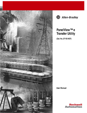
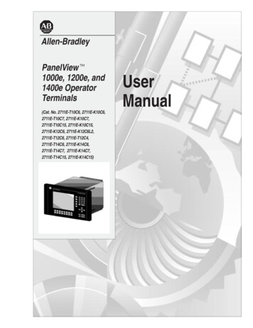
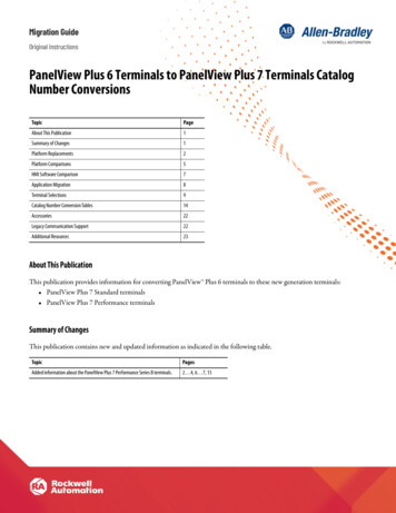
6PanelView 600 TerminalsMounting Dimensions192 mm(7.55 in.)290 mm(11.40 in.)6.9 mm(0.27 in.)Top View91 mm(3.60 in.)116 mm(4.57 in.)Cutout DimensionsUse the full size template shipped with the terminal to mark the cutout dimensions.The figure below shows a reduced size cutout.PanelView 600 Terminals167 mm(6.57 in.)Recommended PanelCutout Dimensions264 mm(10.39 in.)Publication 2711-IN010G-EN-P - February 2009
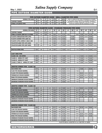
PanelView 600 Terminals7ClearancesAllow adequate space for mounting, air flow, maintenance, and for installing amemory card, and legend inserts.Side, Top and Bottom ClearancesLeave 51 mm (2 in.)for Mounting and Air flowTERMINAL CUTOUTUse Full SizeTemplate shipped withTerminalFront ViewLeave 25 mm (1 in.)Leave 51 mm (2.0 in.)Leave 38 mm (1.5 in.) for Mounting,for Mounting and Air Flow for Mounting and Wiring Connections Air Flow and Legend Insert6.9 mm(0.27 in)Approximately220 mm (8.65 in.) is 91 mmrequired to insert and(3.60 in.)remove a memory cardwith the memory cardcardretainer.Back ClearanceTop View116 mm(4.57 in.)Memory Card RetainerPublication 2711-IN010G-EN-P - February 2009
8PanelView 600 TerminalsInstall the Terminal in a PanelTo install the PV600 terminal in a panel:ATTENTION Disconnect all electrical power from the panel before making the cutout. Make sure the area around the panel cutout is clear. Take precautions so that metal cuttings do not enter any components that mayalready be installed in panel. Failure to follow this warning may result in personal injury or damage to the panelcomponents.1. Cut an opening in the panel using the panel cutout provided with theterminal. Remove any sharp edges or burrs.2. Make sure the terminal sealing gasket is properly positioned on the terminalas shown below. This gasket forms a compression type seal. Do not usesealing compounds.Sealing Gasket3. Although the keypad legend strip can be installed at any time, werecommend that you install it after the terminal is installed.4. Place the terminal in the panel cutout.Publication 2711-IN010G-EN-P - February 2009
PanelView 600 Terminals95. Install the 4 mounting clips (2 on top, 2 on bottom); the ends of the clipsslide into the slots on the terminal. Tighten the clip mounting screws byhand until the gasket seal contacts the mounting surface uniformly.Install 4 Mounting Clips:Top - Left and Right SlotsBottom - Left and Right SlotsProtective Installation Labels6. Alternately tighten the mounting clip screws to a torque of 1.13 N m(10 lb in). Do not over–tighten.ATTENTIONTighten mounting clips to a torque of 1.13 N m (10 lb in) to provide a properseal and to prevent potential damage to the terminal. Allen-Bradley assumes noresponsibility for water or chemical damage to the terminal or other equipmentwithin the enclosure because of improper installation.7. Remove the 2 protective labels covering the top vents of the terminal.ATTENTIONRemove the protective installation labels covering the top vents to preventoverheating and damage to the terminal.Publication 2711-IN010G-EN-P - February 2009
10PanelView 600 TerminalsInstall the Memory CardThe memory card retainer is required for UL508 installations where a memory cardis inserted in the card slot. The retainer protects against Electrostatic Discharge(ESD) up to 15 KV and prevents accidental removal of a memory card in highvibration environments.To attach the memory card retainer:Retainer BaseMemory CardRetainerBase Mounting Screws1. Secure the base of the retainer over the existing memory card slot using thetwo screws provided. Tighten screws to a torque of 0.7 0.9 N m(6 8 lb in).2. Insert the memory card and install the retainer until it is properly seated.3. To remove the retainer, press the tabs on each side and pull.Publication 2711-IN010G-EN-P - February 2009
PanelView 600 Terminals11Connect AC PowerThe electrical rating for the PanelView 600 terminal is shown below.Terminal TypeSupply VoltagePower ConsumptionPV60085 240V AC, 47 63 Hz60 VA maximumThe PanelView 600 terminal is an IEC 1131-2 Equipment Class I device and requiresyou to connect the(Protective Earth) terminal to an earth conductor.ATTENTION The PanelView 600 terminal is designed for safe use when installed in a suitablyrated NEMA Type 12, 13, 4X (indoor use only), IP54 or IP65 enclosure. Do not apply power to the terminal until all wiring connections have been made.Failure to do so may result in electrical shock.WARNINGExplosion Hazard - Do not connect or disconnect equipment while circuit is live unlessarea is known to be non-hazardous.To connect AC power to the PanelView 600 terminals:1. Secure the AC power wires to the L1 and L2N screws on the terminal block.2. Secure the Earth Ground/Protective Earth wire to theterminal block.ATTENTIONscrew on theImproper wiring of the power terminals may result in voltage at thecommunication connector shells. Refer to the following figure when wiring.Publication 2711-IN010G-EN-P - February 2009
12PanelView 600 Terminals3. Apply power to the terminal.120/240V AC, 3 Wire,U.S. Color Code120/240V AC, 3 Wire, EuropeanHarmonized Color CodeL1 L2Black (line)White(neutral)L1 L2GreenGreenBrown (line)(earth ground)Blue(neutral)To Power SourceGreen/Yellow(protective earth)Power TerminalBlock (fixed)To Power SourceConnect DC PowerThe L1 versions of the PanelView 600 terminal (catalog number 2711-K6C1L1,2711-B6C1L1) connect to a 24V DC power source.The electrical ratings for the PanelView 600 are shown below. Electronic circuitryand an internal fuse protect the terminal from reverse polarity and over–voltageconditions.Terminal TypeSupply VoltagePower ConsumptionPV60018 32V DC,(24V DC nominal)24 Watts maximum(1.0 Amps @ 24V DC)ATTENTIONFor DC powered units, use a Class 2/SELV (Safety Extra-Low Voltage), isolated andungrounded power supply as input power to the terminals. This power source providesprotection so that under nominal and single fault conditions, the voltage betweenconductors and between conductors and Functional Earth/Protective Earth does notexceed a safe value.Publication 2711-IN010G-EN-P - February 2009
PanelView 600 TerminalsATTENTION13 Do not connect the PanelView terminal to an AC power source. Connecting to an ACpower source may damage the terminal. The PanelView 600 terminal is designed for safe use when installed in a suitablyrated NEMA Type 12, 13, 4X (indoor use only), IP54 or IP65 enclosure.To connect DC power to the PV600 terminal:1. Secure the DC power wires to the DC Negative and DC Positive screws onthe terminal block.2. Secure the Earth Ground wire to thescrew on the terminal block.WARNINGExplosion Hazard - Do not connect or disconnect equipment while circuit is liveunless area is known to be non-hazardous.ATTENTIONDo not apply power to the terminal until all wiring connections have been made.Failure to do so may result in electrical shock.3. Apply 24V DC power to the terminal.Power TerminalBlock (fixed) Earth GroundDC NegativeDC PositivePublication 2711-IN010G-EN-P - February 2009
14PanelView 600 TerminalsEtherNet/IP ProtocolThe PanelView terminal is initially set to DHCP with BootP support (Dynamic HostConfiguration Protocol) enabled. If your network has a DHCP/BootP server, youcan connect the PanelView terminal to the EtherNet/IP network and theDHCP/BootP server will automatically establish an IP address. If your network doesnot have a DHCP/BootP server, you need to program an IP address. This is done byaccessing Configuration Mode on the PanelView terminal and selectingCommunication Setup. For details, refer to the PanelView Standard OperatorTerminals Manual.IMPORTANTIf a PanelView is connected to an EtherNet/IP network and has the same IP address asanother device on the network, both devices will drop off the network.ControlNet ProtocolIMPORTANTWhen making ControlNet connections, only use the PanelView Channel B for redundantcommunications. Connecting Channel B to a Channel A only ControlNet network willresult in: the PanelView not being able to communicate over the network. a PanelView communications fault after several minutes.Battery Removal and DisposalThe terminal contains a lithium battery, which is intended to be replaced during thelife of the product.ATTENTIONThe clock module contains lithium. Do not dispose of the battery in a fire or incinerator, orthe clock module may explode. Follow disposal regulations in your area for lithiumbattery disposal.At the end of its life, the battery contained in this product should be collected separatelyfrom any unsorted municipal waste.Publication 2711-IN010G-EN-P - February 2009
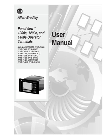
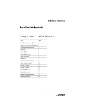
PanelView 600 Terminals15Follow these steps to remove or replace the battery.21345678For More InformationForRefer toRefer toMore detailed information on the PV600 and theother Standard PanelView terminals.Standard PanelViewTerminals User Manual2711-UM014If you would like a publication, you can download a free electronic version fromthe internet: http://www.literature.rockwellautomation.comTo purchase a publication, contact your local distributor or Rockwell AutomationRepresentative.Publication 2711-IN010G-EN-P - February 2009
Rockwell Automation SupportRockwell Automation provides technical information on the Web to assist you inusing its products. At http://support.rockwellautomation.com, you can findtechnical manuals, a knowledge base of FAQs, technical and application notes,sample code and links to software service packs, and a MySupport feature that youcan customize to make the best use of these tools.For an additional level of technical phone support for installation, configuration andtroubleshooting, we offer TechConnect support programs. For more information,contact your local distributor or Rockwell Automation representative, or ation AssistanceIf you experience a problem within the first 24 hours of installation, please reviewthe information that's contained in this manual. You can also contact a specialCustomer Support number for initial help in getting your product up and running.United States1.440.646.3434Monday – Friday, 8 a.m. – 5 p.m. ESTOutside UnitedStatesPlease contact your local Rockwell Automation representative for anytechnical support issues.New Product Satisfaction ReturnRockwell Automation tests all of its products to ensure that they are fullyoperational when shipped from the manufacturing facility. However, if yourproduct is not functioning and needs to be returned, follow these procedures.United StatesContact your distributor. You must provide a Customer Support case number(call the phone number above to obtain one) to your distributor in order tocomplete the return process.Outside UnitedStatesPlease contact your local Rockwell Automation representative for the returnprocedure.PanelView, PanelView 600, Allen-Bradley, Rockwell Automation, and TechConnect are trademarks ofRockwell Automation, Inc.Trademarks not belonging to Rockwell Automation are property of their respective companies.Publication 2711-IN010G-EN-P - February 2009Supersedes Publication 2711-IN010F-MU-P - August 2007PN-40536Copyright 2009 Rockwell Automation, Inc. All rights reserved. Printed in the U.S.A.
a safety measure in electrical installations. To avoid EMI, shield and ground cables appropriately. A source for grounding recommendations is the National Electrical Code published by the National Fire Protection Association of Boston. Enclosures The PanelView 600 terminal must be mounted in an environment that provides