Transcription
PanelView Plus Compact TerminalsUser ManualCatalog Numbers 2711PC-K4M20D,2711PC-B4C20D, 2711PC-T6M20D,2711PC- T6C20D, 2711PC-T10C4D1
Important User InformationSolid state equipment has operational characteristics differing from those of electromechanical equipment. Safety Guidelinesfor the Application, Installation and Maintenance of Solid State Controls (publication SGI-1.1 available from your localRockwell Automation sales office or online at http://literature.rockwellautomation.com) describes some important differencesbetween solid state equipment and hard-wired electromechanical devices. Because of this difference, and also because of thewide variety of uses for solid state equipment, all persons responsible for applying this equipment must satisfy themselvesthat each intended application of this equipment is acceptable.In no event will Rockwell Automation, Inc. be responsible or liable for indirect or consequential damages resulting from theuse or application of this equipment.The examples and diagrams in this manual are included solely for illustrative purposes. Because of the many variables andrequirements associated with any particular installation, Rockwell Automation, Inc. cannot assume responsibility or liabilityfor actual use based on the examples and diagrams.No patent liability is assumed by Rockwell Automation, Inc. with respect to use of information, circuits, equipment, orsoftware described in this manual.Reproduction of the contents of this manual, in whole or in part, without written permission of Rockwell Automation, Inc., isprohibited.Throughout this manual, when necessary, we use notes to make you aware of safety considerations.WARNINGIMPORTANTATTENTIONIdentifies information about practices or circumstances that can cause an explosion in ahazardous environment, which may lead to personal injury or death, property damage, oreconomic loss.Identifies information that is critical for successful application and understanding of the product.Identifies information about practices or circumstances that can lead to personal injury or death,property damage, or economic loss. Attentions help you identify a hazard, avoid a hazard, andrecognize the consequenceSHOCK HAZARDLabels may be on or inside the equipment, for example, a drive or motor, to alert people thatdangerous voltage may be present.BURN HAZARDLabels may be on or inside the equipment, for example, a drive or motor, to alert people thatsurfaces may reach dangerous temperatures.Allen-Bradley, PanelView Plus, PanelView Plus Compact, FactoryTalk View, FactoryTalk View ME, FactoryTalk View Studio, FactoryTalk ViewPoint, RSLinx Enterprise, Rockwell Automation, and TechConnectare trademarks of Rockwell Automation, Inc.Trademarks not belonging to Rockwell Automation are property of their respective companies.
Table of ContentsPrefaceIntended Audience . . . . . . . . . . . . . . . . . . . . . . . . . . . . . . . . 7Parts List. . . . . . . . . . . . . . . . . . . . . . . . . . . . . . . . . . . . . . . . 7Additional Resources. . . . . . . . . . . . . . . . . . . . . . . . . . . . . . . 7Chapter 1OverviewChapter Objectives . . . . . . . .Product Overview . . . . . . . . .Catalog Number Explanation .Software Support . . . . . . . . .Hardware Configurations. . . .Displays . . . . . . . . . . . . . . . .Accessories . . . . . . . . . . . . . . 9. 9. 910101111Chapter Objectives . . . . . . . . . . . . . . . . .Hazardous Locations . . . . . . . . . . . . . . . .Environment and Enclosure. . . . . . . . . . .Required Tools . . . . . . . . . . . . . . . . . . . .Clearances . . . . . . . . . . . . . . . . . . . . . . .Cutout Dimensions . . . . . . . . . . . . . . . . .Mount the 400 or 600 Terminal in a PanelMount the 1000 Terminal in a Panel. . . . .Product Dimensions . . . . . . . . . . . . . . . .131316171717182022Chapter Objectives . . . . . . . . . . . . . . . . . . . . . . . .Wiring and Safety Guidelines. . . . . . . . . . . . . . . . .Removing and Installing the Power Terminal BlockConnecting Power. . . . . . . . . . . . . . . . . . . . . . . . .Resetting the Terminals . . . . . . . . . . . . . . . . . . . . .2323242629.31313536363637414547505354Chapter 2Installing the TerminalChapter 3Connecting PowerChapter 4Configuring the Terminal3Publication 2711PC-UM001A-EN-P - March 2009Chapter Objectives . . . . . . . . . . . . . . . . . . . .Accessing Configuration Mode. . . . . . . . . . . .Loading an Application . . . . . . . . . . . . . . . . .Running an Application. . . . . . . . . . . . . . . . .Application Settings. . . . . . . . . . . . . . . . . . . .Terminal Settings . . . . . . . . . . . . . . . . . . . . .Configuring Communication . . . . . . . . . . . . .Configuring Network Information . . . . . . . . .Configuring Diagnostics . . . . . . . . . . . . . . . .Managing Files on the Terminal. . . . . . . . . . .Modifying Display Settings . . . . . . . . . . . . . .Font Linking . . . . . . . . . . . . . . . . . . . . . . . . .Configuring the Keypad, Keyboard, or Mouse.3
Table of ContentsConfiguring the Touch Screen . . . . . . . . .Configuring Print Options . . . . . . . . . . . .Configuring Startup Options . . . . . . . . . .Configuring Startup Tests. . . . . . . . . . . . .Clearing the System Event Log. . . . . . . . .Displaying Terminal Information . . . . . . .DisplayingFactoryTalk View ME Station Information.Modifying the Date, Time, or Time Zone .Modifying Regional Settings. . . . . . . . . . .565860636566. . . . . . . . . . . . . . 68. . . . . . . . . . . . . . 69. . . . . . . . . . . . . . 71Chapter 5Installing and ReplacingComponentsChapter Objectives . . . . . . . . . . . . . .Required Tools . . . . . . . . . . . . . . . . .Precautions. . . . . . . . . . . . . . . . . . . .Replacing the Battery . . . . . . . . . . . .Replacing the Backlight . . . . . . . . . . .Using an External CompactFlash CardRemoving the Product ID Label . . . . .Replacing the Bezel. . . . . . . . . . . . . .Cleaning theDisplay Window . . . . . . . . . . . . . . . .7575757679818283. . . . . . . . . . . . . . . . . 85Chapter 6Terminal ConnectionsChapter Objectives . . . . . . . . . . . . .Cables for Runtime Communication .Communication Port Isolation . . . . .USB Ports . . . . . . . . . . . . . . . . . . . .Serial Connections. . . . . . . . . . . . . .Ethernet Connections . . . . . . . . . . .878788899093Chapter 7Upgrading Firmware4Chapter Objectives . . . . . . . . . . . . . . . . . . . . . . .Transferring Applications. . . . . . . . . . . . . . . . . . .Firmware Upgrade Wizard. . . . . . . . . . . . . . . . . .Preparing Terminalfor Upgrade . . . . . . . . . . . . . . . . . . . . . . . . . . . .Upgrading Firmware with a CompactFlash Card . .Upgrading Firmware over a Network Connection . . . . . . . . 95. . . . . . . . 95. . . . . . . . 95. . . . . . . . 95. . . . . . . . 96. . . . . . . 100Publication 2711PC-UM001A-EN-P - March 2009
Table of ContentsChapter 8TroubleshootingChapter Objectives . . . . . . . . . .Status Indicators . . . . . . . . . . . .Isolating the Problem . . . . . . . .Startup Information Messages . .Startup Sequence . . . . . . . . . . .Startup Error Messages . . . . . . .Checking Terminal ComponentsEthernet Connection . . . . . . . . .Hardware Compatibility. . . . . . .Application Does Not Load . . . .Application Does Not Run . . . . .Configuration Mode Access . . . 119119Appendix ASpecificationsElectrical. . . . . . . . . .Environmental . . . . .Display . . . . . . . . . . .Mechanical . . . . . . . .General . . . . . . . . . .Agency Certifications.Appendix BUSB DevicesCompatible USB Devices . . . . . . . . . . . . . . . . . . . . . . . . . . 121Appendix CAvailable FontsIndexPublication 2711PC-UM001A-EN-P - March 2009Download Fonts to Terminal . . . . . . . . . . . . . . . . . . . . . . . 123Machine Edition Fonts CD . . . . . . . . . . . . . . . . . . . . . . . . . 124. . . . . . . . . . . . . . . . . . . . . . . . . . . . . . . . . . . . . . . . . . . . 1275
Table of Contents6Publication 2711PC-UM001A-EN-P - March 2009
PrefaceIntended AudienceUse this manual if you are responsible for installing, configuring, andoperating the PanelView Plus Compact terminals.No special knowledge is required to understand this manual oroperate the terminal. However, you must understand the functionsand operations of the FactoryTalk View ME applications that will runon the terminal. Consult the application designer for this information.Equipment installers must be familiar with standard panel installationtechniques.Parts ListYour terminal is shipped with these items: Additional ResourcesPower terminal blockFactoryTalk View ME runtime software preloadedMounting levers or mounting clips (model dependent)Panel cutout templateInstallation instructionsThe table lists resources available for the PanelView Plus terminals.ResourceDescriptionPanelView Plus 400 and 600 TerminalsInstallation Instructions, publication2711P-IN002Provides details on how to install theterminals in a panel, and wire power.PanelView Plus 700 to 1500 Terminals andDisplay Modules, and PanelView PlusCompact 1000 Terminals, InstallationInstructions, publication 2711P-IN001Provides details on how to install theterminals in a panel, and wire power.Wiring and Grounding Guidelines forPanelView Plus Devices Technical Data,publication 2711P-TD001Provides grounding and wiring guidelinesfor PanelView Plus terminals.You can view or download publications athttp://literature.rockwellautomation.com. To order paper copies oftechnical documentation, contact your local Rockwell Automationdistributor or sales representative.7Publication 2711PC-UM001A-EN-P - March 20097
Preface8Publication 2711PC-UM001A-EN-P - March 2009
Chapter1OverviewChapter ObjectivesThis chapter covers these topics: Product description Catalog number explanation Software support Terminal configurations Display modules AccessoriesProduct OverviewThe PanelView Plus Compact terminals are similar to some PanelViewPlus terminal configurations but with limited hardware and softwarefunctions. Major differences of the compact terminals include: Fixed hardware configuration, without the addition orreplacement of modular components. Serial and Ethernet communication only. Connection to a single logic controller using either RSLinxEnterprise or KEPServer Enterprise software, not both. Limited number of displays and alarms in the FactoryTalk ViewMachine Edition (ME) application and runtime software. FactoryTalk ViewPoint software is not supported. Primary HMI for CompactLogix controllers.TIPCatalog NumberExplanationCat. 6C20D2711PC-T10C4D19Publication 2711PC-UM001A-EN-P - March 2009Applications created for PanelView Plus Compact terminals arereferred to as Compact Machine Edition applications. You canrun compact applications on PanelView Plus and PanelViewPlus Compact terminals. You cannot run a regular MachineEdition application created for a PanelView Plus terminal on aPanelView Plus Compact terminal.The table provides catalog number configurations for the PanelViewPlus Compact terminals.Display Size4 inchOperator InputDisplay TypeKeypadMonochromeKeypad and TouchColor6 inchTouch10 inchTouchMonochromeInput PowerDCColorColor9
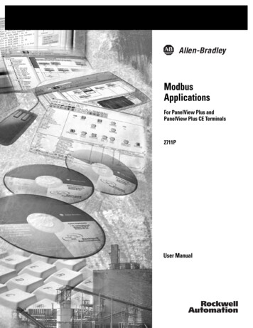
Chapter 1OverviewSoftware SupportEach terminal is preloaded with FactoryTalk View Machine Editionruntime and configuration software that does not require activation.Applications for the compact terminals are created using FactoryTalkView Studio software.Software RequirementsVersionFactoryTalk View Studio5.1 or laterRSLinx Enterprise(1)5.20 or later(1)RSLinx Enterprise software is provided with FactoryTalk View Studio. During software installation, you areprompted to install RSLinx Enterprise software.Compact Machine Edition applications are restricted to a subset of thefunctions allowed on the PanelView Plus terminals. Maximum of 25 displays Maximum of 200 alarm messages Maximum screen resolution of 640 x 480 (VGA) one connection or shortcut to a single controller using eitherRSLinx Enterprise 5.20 or KEPServer Enterprise. Serial and Ethernet communication only.If using RSLinx Enterprise, only serial-DF1, serial-DH485 andEthernet drivers are supported.Hardware ConfigurationsThe terminal configurations are fixed and do not supportcommunication modules. The 1000 touch terminal has a fixed displaymodule and logic module that cannot be replaced.400 and 600 Configurations1000 Configuration5514213ItemDescription1USB port(1)2RS-232 serial port310/100BaseT Ethernet port4Power input, 24V DC5CompactFlash Type 1 card slot(1)10234The 400 and 600 models have one USB port; the 1000 model have two USB ports.Publication 2711PC-UM001A-EN-P - March 2009
OverviewDisplaysChapter 1The terminal configurations provide monochrome or color displayswith keypad, touch, or keypad/touch input.Keypad Description of 400 TerminalsKeysDescriptionF1 through F8Programmable keys that initiate functions on terminal display.Numeric Keypad0 9, ., -, Backspace, Enter, Left and Right Tab keys, Shift keysNavigation KeysUse the arrow keys for navigation.Use the Alt arrow keys to activate home, end, page up, and pagedown functions.ATTENTIONAccessoriesUse a finger or gloved finger to operate the keypad. To operatethe touch screen, use your finger, gloved finger, or plastic styluswith a minimum tip radius of 1.3 mm (0.051 in.). Using otherobject or tool may damage the touch screen or keypad.The compact terminals use many of the same accessories as thePanelView Plus terminals with the exception of the display modules,communication modules, logic modules, and memory.IMPORTANTThe PanelView Plus Compact terminals do not support theaddition or replacement of modular components.Compact Flash CardsCat. No.Description2711P-RC2128 MB blank CompactFlash card2711P-RC3256 MB blank CompactFlash card2711P-RC4512 MB blank CompactFlash card2711P-RCHCompactFlash to PCMCIA adapterBacklightPublication 2711PC-UM001A-EN-P - March 2009Cat. No.Description2711P-RL10C2Replacement color backlight for 1000 series B and C displays11
Chapter 1OverviewReplacement BezelsCat. No.Description2711P-RBT10Replacement bezel for 1000 touch terminalProtective Antiglare OverlaysCat. No.Description2711P-RGK4Antiglare overlay (3) for PanelView Plus 400 keypad terminal2711P-RGB4Antiglare overlay (3) for PanelView Plus 400 color keypad/touch terminal2711P-RGT6Antiglare overlay (3) for PanelView Plus 600 touch terminal2711P-RGT6Antiglare overlay (3) for PanelView Plus 600 touch terminal2711P-RGT10 Antiglare overlay (3) for PanelView Plus 1000 touch terminalAdapter PlatesCat. No.Description2711P-RAK4Adapts a PanelView Plus 400 keypad terminal to a PanelViewStandard 550 keypad cutout2711P-RAT10Adapts a PanelView Plus 1000 touch terminal to a PanelView1000/1000E touch cutoutCablesCat. No.Description2711-NC13RS-232 operating/programming cable (9-pin D-shell to 9-pin D-shell), 5m (16.4 ft)2711-NC14RS-232 operating/programming cable (9-pin D-shell to 9-pin D-shell),10 m (32.7 ft)2711-NC17Remote RS-232 serial cable (9-pin D-shell to 9-pin D-shell)2711-NC21RS-232 operating cable (9-pin D-shell to 8-pin mini DIN), 5 m (16.4 ft)2711-NC22RS-232 operating cable (9-pin D-shell to 8-pin mini DIN), 10 m (32.7 ft)2711P-CBL-EX04Ethernet CAT5 crossover cable, industrial grade, 4.3 m (14 ft)Communication AdaptersCat. No.Description1761-NET-AICAIC advanced interface converterMiscellaneous12Cat. No.Description2711P-RY2032Replacement battery for 1000 terminal2711P-RTMCReplacement mounting clips for 1000 terminals, quantity of 82711P-RTFCReplacement mounting levers for 400 and 600 terminals, quantity of 82711-TBDCReplacement DC power terminal block for 400 and 600 terminals2711P-RTBDC2Replacement two-position DC power terminal block for 1000 terminalPublication 2711PC-UM001A-EN-P - March 2009
Chapter2Installing the TerminalChapter ObjectivesThis chapter provides pre-installation information and procedures onhow to install the terminals. Hazardous LocationsHazardous locationsEnvironment and enclosureRequired toolsClearancesPanel cutout dimensionsMount the 400 or 600 terminal in a panelMount the 1000 terminal in a panelProduct dimensionsThis equipment is suitable for these locations: Class I, Division 2, Groups A, B, C, DClass II, Division 2, Groups F, GClass IIIordinary, nonhazardous locationsThe following statement applies to use in hazardous locations.WARNINGExplosion Hazard Substitution of components may impair suitability for hazardouslocations. Do not disconnect equipment unless power has been switched offand area is known to be nonhazardous. Do not connect or disconnect components unless power has beenswitched off. All wiring must comply with N.E.C. articles 501, 502, 503, and/orC.E.C. section 18-1J2 as appropriate. Peripheral equipment must be suitable for the location in which it isused.The terminals have a temperature code of T4 when operating in a55 C (131 F) maximum ambient temperature. Do not install theterminals in environments where atmospheric gases have ignitiontemperatures less than 135 C (275 F).13Publication 2711PC-UM001A-EN-P - March 200913
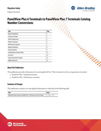
Chapter 2Installing the TerminalUSB PortsThe PanelView Plus Compact terminals contain universal serial bus(USB) ports that comply with hazardous location environments. Thissection details the field-wiring compliance requirements and isprovided in accordance with the National Electrical Code, article 500.PanelView Plus Compact Terminals Control DrawingAssociated Nonincendive Field Wiring ApparatusNonincendive FieldWiring ApparatusPanelView Plus 400, 600, or 1000 Host ProductUSBPeripheralDeviceNonincendive Field WiringUSB PortTable 1 - PanelView Plus Compact USB Port Circuit ParametersCaVocDisplay SizeIscLaGroupsA and BGroupsC and DGroupsA and BGroupsC and D400 and 600Series C or later5.25V DC 1.68 A10 µF10 µF3.5 µH15 µH10005.25V DC 1.68 A10 µF10 µF15 µH15 µHSelected nonincendive field wiring apparatus must have nonincendivecircuit parameters conforming with Table 2.Table 2 - Required Circuit Parameters for the USB Peripheral Device14Vmax VocImax IscCi Ccable CaLi Lcable LaPublication 2711PC-UM001A-EN-P - March 2009
Installing the TerminalChapter 2Application InformationPer the National Electrical Code the circuit parameters ofnonincendive field wiring apparatus for use in hazardous locationsshall be coordinated with the associated nonincendive field wiringapparatus such that their combination remains nonincendive. ThePanelView Plus terminal and the USB peripheral device shall betreated in this manner.The circuit parameters of the PanelView Plus terminal USB port aregiven in Table 1. The USB peripheral device and its associated cablingshall have circuit parameters with the limits given in Table 2 for themto remain nonincendive when used with the PanelView Plus terminalUSB port. If cable capacitance and inductance are not known thefollowing values from ANSI/ISA-RP 12.06.01-2003 may be used:Ccable 197 pF/m (60 pF/ft)Lcable 0.7 µH/m (0.20 µH/ft)Nonincendive field wiring must be wired and separated in accordancewith 501.10(B)(3) of the National Electrical Code (NEC) ANSI/NFPA 70or other local codes as applicable.This associated nonincendive field wiring apparatus has not beenevaluated for use in combination with another associatednonincendive field wiring apparatus.Symbol DefinitionsPublication 2711PC-UM001A-EN-P - March 2009VocOpen circuit voltage of the host USB port.IscMaximum output current of the host USB port.VmaxMaximum applied voltage rating of the USB peripheral device.Vmax shall be greater than or equal to Voc in Table 1. (Vmax Voc ).ImaxMaximum current to which the USB peripheral device can be subjected.Imax shall be greater than or equal to Isc in Table 1. (Imax Isc).CiMaximum internal capacitance of the USB peripheral device.CaMaximum allowed capacitance of the USB peripheral device and itsassociated cable. The sum of Ci of the USB peripheral device and Ccable ofthe associated cable shall be less than or equal to Ca . (Ci Ccable Ca).LiMaximum internal inductance of the USB peripheral device.LaMaximum allowed inductance of the USB peripheral device and itsassociated cable. The sum of Li of the USB peripheral device and Lcable ofthe associated cable shall be less than or equal to La . (Li Lcable La).15
Chapter 2Installing the TerminalEnvironment and EnclosureATTENTIONThis equipment is intended for use in a Pollution Degree 2industrial environment, in overvoltage Category II applications(as defined in IEC 60664-1), at altitudes up to 2000 m (6561 ft)without derating.The terminals are intended for use with programmable logiccontrollers. Terminals that are AC powered must also beconnected to the secondary of an isolating transformer.This equipment is considered Group 1, Class A industrialequipment according to IEC CISPR 11. Without appropriateprecautions, there may be difficulties ensuring electromagneticcompatibility in residential and other environments due toconducted or radiated disturbances.This equipment is supplied as open-type equipment. It must bemounted within an enclosure that is suitably designed for thosespecific environmental conditions that will be present andappropriately designed to prevent personal injury resulting fromaccessibility to live parts. The interior of the enclosure must beaccessible only by the use of a tool. The terminals meetspecified NEMA Type and IEC ratings only when mounted in apanel or enclosure with the equivalent rating. Subsequentsections of this publication may contain additional informationregarding specific enclosure type ratings that are required tocomply with certain product safety certifications.In addition to this publication, see: Industrial Automation Wiring and Grounding Guidelines,publication 1770-4.1, for additional installation requirements. NEMA Standards 250 and IEC 60529, as applicable, forexplanations of the degrees of protection provided by differenttypes of enclosure.16Publication 2711PC-UM001A-EN-P - March 2009
Installing the TerminalChapter 2Required ToolsThese tools are required for panel installation: Panel cutout tools Small, slotted screwdriver Torque wrench (lb in) for tightening the mounting clips on the1000 terminalClearancesAllow adequate clearance around the terminal, inside the enclosure,for adequate ventilation. Consider heat produced by other devices inthe enclosure. The ambient temperature around the terminals must bebetween 0 55 C (32 131 ºF).Clearance Area 400 and 600 Terminals1000 TerminalTop51 mm (2 in.)51 mm (2 in.)Bottom102 mm (4 in.)51 mm (2 in.)Side(1)25 mm (1 in.)25 mm (1 in.)BackNone25 mm (1 in.)(1)Cutout DimensionsPublication 2711PC-UM001A-EN-P - March 2009Minimum side clearance for insertion of memory card and cable wiring is 102 mm (4 in.).Use the full size template shipped with your terminal to mark thecutout dimensions.Terminal TypeHeight mm (in.)Width mm (in.)400 Keypad, or Keypad and Touch123 (4.86)156 (6.15)600 Touch123 (4.86)156 (6.15)1000 Touch224 (8.8)305 (12.00)17
Chapter 2Installing the TerminalMount the 400 or 600Terminal in a PanelMounting levers secure the terminal to the panel. The number oflevers you use (4 or 6) varies by terminal type.ATTENTIONDisconnect all electrical power from the panel before makingthe panel cutout.Make sure the area around the panel cutout is clear.Take precautions so metal cuttings do not enter anycomponents already installed in the panel.Failure to follow these warnings may result in personal injury ordamage to panel components.Follow these steps to mount the 400 or 600 terminals in a panel.1. Cut an opening in the panel by using the panel cutout shippedwith the terminal.2. Make sure the terminal sealing gasket is properly positioned onthe terminal.This gasket forms a compression-type seal. Do not use sealingcompounds.Sealing Gasket3. Place the terminal in the panel cutout.If installing the terminal in an existing 550 panel cutout, alignthe terminal with the center of the cutout for best gasket sealing.4. Insert all mounting levers into the mounting slots on theterminal.18Publication 2711PC-UM001A-EN-P - March 2009
Installing the TerminalChapter 2Slide each lever until the flat side of the lever touches thesurface of the panel.Mounting SlotsMounting LeversFlat Side of Lever5. When all levers are in place, slide each lever an additional notchor two until you hear a click.6. Rotate each lever in the direction indicated until it is in the finallatch position.Follow the latching sequence for the optimum terminal fit.144 LeversNotch631Alignment MarksRotate lever until notch inlever aligns with properalignment mark on terminal.21536 Levers426Use this table as a guide to provide an adequate gasket sealbetween the terminal and the panel.13 26 5 4Terminal Markingsor AlignmentLever PositionPanel Thickness RangeTypical Gauge11.52 2.01 mm (0.060 0.079 in.)1622.03 2.64 mm (0.08 0.104 in.)1432.67 3.15 mm (0.105 0.124 in.)1243.17 3.66 mm (0.125 0.144 in.)1053.68 4.16 mm (0.145 0.164 in.)8/964.19 4.75 mm (0.165 0.187 in.)7ATTENTIONPublication 2711PC-UM001A-EN-P - March 2009Follow instructions to provide a proper seal and toprevent potential damage to the product. RockwellAutomation assumes no responsibility for water orchemical damage to the terminal or other equipmentwithin the enclosure because of improper installation.19
Chapter 2Installing the TerminalMount the 1000 Terminal ina PanelMounting clips secure the terminal to the panel.ATTENTIONDisconnect all electrical power from the panel before makingthe panel cutout.Make sure the area around the panel cutout is clear.Take precautions so metal cuttings do not enter anycomponents already installed in the panel.Failure to follow these warnings may result in personal injury ordamage to panel components.Follow these steps to mount the terminal in a panel.1. Cut an opening in the panel by using the panel cutout shippedwith the terminal.2. Make sure the terminal sealing gasket is properly positioned onthe terminal.This gasket forms a compression-type seal. Do not use sealingcompounds.Sealing Gasket3. Place the terminal in the panel cutout.20Publication 2711PC-UM001A-EN-P - March 2009
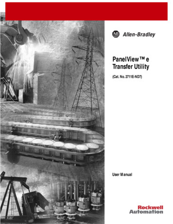
Installing the TerminalChapter 24. Slide the ends of the mounting clips into the slots on terminal.Mounting ClipMounting Clip Slot5. Tighten the mounting clip screws by hand until the gasket sealcontacts the mounting surface uniformly.6. Tighten the mounting clips screws to a torque of 0.90 1.1 N m(8 10 lb in) by using the specified sequence, making sure notto overtighten.14Torque Sequence3ATTENTIONPublication 2711PC-UM001A-EN-P - March 20092Tighten the mounting clips to the specified torque toprovide a proper seal and to prevent damage to theproduct. Allen-Bradley assumes no responsibility forwater or chemical damage to the product or otherequipment within the enclosure because of improperinstallation.21
Chapter 2Installing the TerminalProduct DimensionsProduct dimensions for each terminal are in mm (in.).PanelView Plus 400 Keypad or Keypad/Touch Dimensions152(6.0)60(2.35)90(3.54)71 (2.81)154 (6.08)185 (7.28)PanelView Plus Compact 600 Touch Dimensions68 (2.68)152 (6.0)98 (3.86)71 (2.81)154 (6.08)185 (7.28)PanelView Plus Compact 1000 Touch Dimensions248(9.7)55 (2.18)329(12.97)22Publication 2711PC-UM001A-EN-P - March 2009
Chapter3Connecting PowerChapter ObjectivesThis chapter covers wiring and safety guidelines, and providesprocedures to: remove and install the power terminal block. connect DC power. reset the terminal.Wiring and SafetyGuidelinesUse publication NFPA 70E Electrical Safety Requirements forEmployee Workplaces, IEC 60364 Electrical Installations in Buildings,or other applicable wiring safety requirements for the country ofinstallation when wiring the devices. In addition to the NFPAguidelines: connect the device and other similar electronic equipment to itsown branch circuit. protect the input power by a fuse or circuit breaker rated at nomore than 15 A. route incoming power to the device by a separate path from thecommunication lines. cross power and communication lines at right angles if theymust cross. Communication lines can be installed in the same conduit aslow-level DC I/O lines (less than 10V). shield and ground cables appropriately to avoid electromagneticinterference (EMI). Grounding minimizes noise from EMI and is a safety measure inelectrical installations.For more information on grounding recommendations, refer to theNational Electrical Code published by the National Fire ProtectionAssociation.For more information, refer to Wiring and Grounding Guidelines forPanelView Plus Devices, publicati
Catalog number explanation Software support Terminal configurations Display modules Accessories Product Overview The PanelView Plus Compact terminals are similar to some PanelView Plus terminal configurations but with limited hardware and software functions. Major differences of the compact terminals include: