Transcription
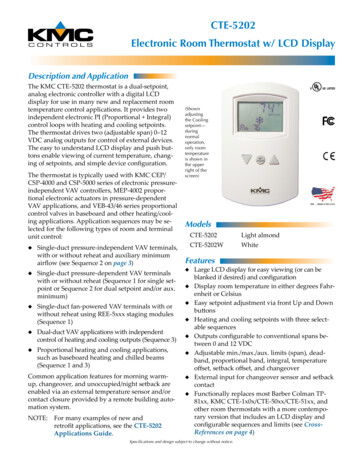
CTE-5202Electronic Room Thermostat w/ LCD DisplayDescription and ApplicationThe KMC CTE-5202 thermostat is a dual-setpoint,analog electronic controller with a digital LCDdisplay for use in many new and replacement roomtemperature control applications. It provides twoindependent electronic PI (Proportional Integral)control loops with heating and cooling setpoints.The thermostat drives two (adjustable span) 0–12VDC analog outputs for control of external devices.The easy to understand LCD display and push buttons enable viewing of current temperature, changing of setpoints, and simple device configuration.The thermostat is typically used with KMC CEP/CSP-4000 and CSP-5000 series of electronic pressureindependent VAV controllers, MEP-4002 proportional electronic actuators in pressure-dependentVAV applications, and VEB-43/46 series proportionalcontrol valves in baseboard and other heating/cooling applications. Application sequences may be selected for the following types of room and terminalunit control: Single-duct pressure-independent VAV terminals,with or without reheat and auxiliary minimumairflow (see Sequence 2 on page 3)(Shownadjustingthe Coolingsetpoint—duringnormaloperation,only roomtemperatureis shown inthe upperright of thescreen)Models Single-duct fan-powered VAV terminals with orwithout reheat using REE-5xxx staging modules(Sequence 1) Dual-duct VAV applications with independentcontrol of heating and cooling outputs (Sequence 3) Proportional heating and cooling applications,such as baseboard heating and chilled beams(Sequence 1 and 3)Common application features for morning warmup, changeover, and unoccupied/night setback areenabled via an external temperature sensor and/orcontact closure provided by a remote building automation system.NOTE:For many examples of new andretrofit applications, see the CTE-5202Applications Guide.Light almondCTE-5202WWhiteFeaturesSingle-duct pressure-dependent VAV terminalswith or without reheat (Sequence 1 for single setpoint or Sequence 2 for dual setpoint and/or aux.minimum) CTE-5202 Large LCD display for easy viewing (or can beblanked if desired) and configurationDisplay room temperature in either degrees Fahrenheit or CelsiusEasy setpoint adjustment via front Up and DownbuttonsHeating and cooling setpoints with three selectable sequencesOutputs configurable to conventional spans between 0 and 12 VDCAdjustable min./max./aux. limits (span), deadband, proportional band, integral, temperatureoffset, setback offset, and changeoverExternal input for changeover sensor and setbackcontactFunctionally replaces most Barber Colman TP81xx, KMC CTE-1x0x/CTE-50xx/CTE-51xx, andother room thermostats with a more contemporary version that includes an LCD display andconfigurable sequences and limits (see CrossReferences on page 4)Specifications and design subject1 to change without notice.
SpecificationsSupply Voltage24 VAC ( 20/–15%), Class 2, or14 to 35 VDC (for full output;@ 9.1 VDC thermostat is fullyfunctional except that AO1and AO2 max. output voltageis reduced to about 5.3 VDC)Supply Power1 VA (VAC) or 0.5 W (VDC)OffsetsRoom temperature offset(adjustable 5 F) and standbysetback offset (adjustable 1 to10 F, default 2 F, does notapply to morning warm-up)DisplayMultifunctional LCD, 1.88 x1.25 inches (48 x 32 mm) withtemperature continuously updated (can be blanked); heat/cool icons and other information displayed when relevantConnector TypeWire clamp terminals, 16 to 26AWGWeight4.2 ounces (119 grams), including backplateMaterialLight almond or white flameresistant plasticMountingThermostat secured to backplate by two concealed screws;backplate mounts to vertical 2x 4 inch standard handy box;mounts to most other boxeswith an HMO-1161 wall plateApprovalsUL 873 Temperature Indicatingand Regulating Equipment;FCC Class B, Part 15, SubpartB and complies with CanadianICES-003 Class B; SASO PCPRegistration KSA R-103263;CE compliantTemperature Sensor 10K ohm Type II thermistorwith 0.36 F ( 0.2 C) accuracyExt. Input (AI1)Analog Input (10K ohm pullup resistor for Type III thermistor as optional changeoversensor—or a contact to initiatesetback)Outputs (AO1/AO2) (Adjustable span) 0 to 12 VDC(10K ohm max. load)Output Limits/Span Minimum, maximum, andauxiliary limits adjustable 0to 12 VDC (defaults min. 0,max. 12, aux. 0)Setpoint Range55 to 85 F (13 to 30 C), withdefault 74 (for cooling or 70 for heating)ChangeoverAdjustable from 55 to 85 F,with 77 F defaultDeadbandMinimum setpoint differentialadjustable 1 to 10 F (0.5 to5.5 C), with default of 2 FProportional BandAdjustable from 1 to 10 F (0.5to 5.5 C), with 2 F defaultIntegral Time0 to 60 minutes; default settingis 30; 0 cancel integral actionAEnvironmental LimitsOperatingHumidityShipping32 to 140 F (0 to 49 C)0 to 95% RH, non-condensing–40 to 160 F (–40 to 71 C)BAO2AO1AI1TT DCSETPOINTE2A3.25 in.83 mmB0.88 in.22 mmC5.16 in.116 mmD3.25 in.83 mmE0.15 in. dia.3.81 mm dia.
SequencesHOT AIR SEQUENCE (Morning Warm Up)COLD AIR SEQUENCE12 VoltsAO2 Disabled(12 Volts)AO1 (DA)AO1 (RA)AO2 (DA)0-12 Volts6 VoltsAO1 MAXAO1 MAXAO1 MINAO1 MIN2 FTemp. Increasing2 F2 FSetpointSetpointSEQUENCE 1: Single Duct Cooling, Fan Box (with REE-5002 or REE-5017)HOT AIR SEQUENCE (Morning Warm Up)COLD AIR SEQUENCE12 VoltsAO2 (RA)AO2 Disabled(0 Volts)AO1 (DA)AO1 (RA)0 VoltsAUXAO1 MAXAO1 MAX10%Of LoopAO1 MIN2 F2 FHeatingSetpointAO1 MINTemp. IncreasingCoolingSetpoint2 FHeatingSetpointSEQUENCE 2: Single Duct Cooling with Reheat and Auxiliary FlowHot/Cold ChangeoverAO2 MAXAO2 (RA)For hot/cold changeover on Sequence 1 or 2, connecta changeover sensor to the AI1 input. The sensorshould be a Type III thermistor (10K ohm @ 77 F),such as KMC STE-140x duct or STE-1454/1455 strapon sensors. (An internal 10K ohm pullup resistor isprovided on AI1.)AO1 (DA)AO2 MINAO1 MAXAO1 MIN2 FLeave sensor off for continuous cold air mode.2 FHeatingSetpointCoolingSetpointUnoccupied/Standby SetbackTemp.IncreasingContact closure across AI1 and Common initiates theunoccupied/standby setback sequence, which causesthe cooling setpoint to increase and the heating setpoint (where applicable) to decrease by the amountof the (selectable) setback offset. In Sequence 2 or 3,it would shift both the cooling setpoint and the heating setpoint. (This setback does not apply during themorning warm-up sequence.)SEQUENCE 3:Independent Heating and Cooling Control(Dual Duct VAV, Baseboard, Single Zone AHU)NOTE: AO1 is typically used to control the coolingoutput (primary air damper or coolingvalve), and AO2 is used to control theheating output (VAV reheat or heatingvalve).3
Cross-ReferencesAccessoriesNOTE: For detailed information, includingsequences to select and sampleapplications, see the CTE-5202Applications Guide.CSP-4702Diff. pressureVAV controller/actuatorThe CTE-5202 is a functional replacement and upgrade for the following thermostats:HMO-1161Wall plate, allows mountingto horizontal 2x 4", 4 x 4", orother boxes,light almondHMO-1161WHMO-1161 inwhiteHPO-0044Replacementcover hexscrewsHPO-1161Foam 0xxElectric relaymodules, staging and reheatSTE-140xDuct temperature (Type III)sensorsSTE-1454/1455Strap-on temperature (TypeIII) sensorsVEB-4xxxxxxxValves (withproportionalactuators) KMC (Nailor, Dynacon) CTE-100x and CTE-110xseries KMC CTE-50xx (except CTE-5003/5013) series KMC (Nailor, Dynacon) CTE-51xx series (exceptfor some features of the CTE-5102/5103/5105) Anemostat (East/West) 13-27, 13-28, 13-29, 13-33,13-34, 13-35, 004100, 004643 ASC / Titus 10269601, 10269603, 10269604,10269606, 10269607, 10269608, 10269609,10269610, 10027401, 10027403, 10027411,10027413, 10027415 Barber Colman (Schneider Electric, TAC, Invensys) TP-8101, TP-8102, TP-8103, TP-8124, andTP-8125 Carnes 999-2662, 999-2663, 999-2664 Honeywell TB7980 (check application and specifications) Johnson Controls (various—check applicationand specifications) Kele RTC-2P (with one or less remote inputs—check application and specifications) Metal Industries 01EC-2119, 01EC-2120, 01EC2122, 01EC-2129, 01EC-2146, 01EC-9229 Metalaire THM1004, THM1005, THM1101,THM1103, THM1105 Nailor B3-3001-191 (B3-191), B3-3001-186 (B3186), B3-3001-015 (B3-015), H1-981 PEKO (various—check application and specifications) Price Industries 019726-001, 019810-001, 019814001, 019816-001, 019822-001 Siemens (various—check application and specifications)19476 Industrial Drive Viconics (various—check application and specifications)574.831.5250 2014 KMC Controls, Inc.; KMC Controls is a registered trademark of KMC ControlsNOTE: For information about use of accessories,see the CTE-5202 Applications Guide.KMC Controls, Inc.New Paris, IN 46553www.kmccontrols.com; info@kmccontrols.com4821-035-02G
Electronic Room Thermostat with LCD DisplayCTE-5202Installation and Operation GuideInstallationACMounting and WiringThe thermostat must NOT be: Mounted on or near a large thermal mass (e.g.,concrete block wall). Blocked from normal air circulation by obstructions. Exposed to heat sources (e.g., lights, computers,copiers, or coffee makers) or to sunlight (at anytime of the day). Exposed to drafts from windows, diffusers, orreturns. Exposed to air flow through the conduit (fromleaks in plenum ducts)—put plumber’s putty orsimilar material inside the conduit to block airflow.TTAO2AO1AI1Mounted on an exterior wall. DB SETPOINTEABCDE3.25 in.5.16 in.0.88 in.3.25 in.0.15 in. diameter83 mm116 mm22 mm83 mm3.81 mm diameterNOTE: For specifications and other information,see the CTE-5202 Data Sheet.1. If the thermostat is locked on the backplate, turnthe two hex screws (in the two outermost holes)in the backplate CLOCKWISE until they (just)clear the cover. Swing the thermostat up andaway from the backplate to remove it.NOTE: For detailed applications, cross-references,accessories, and other information, see theCTE-5202 Applications Guide.Rough-in PreparationFor optimum temperature sensor performance, thethermostat must be mounted on an interior walland away from heat sources, sunlight, windows,air vents, and air circulation obstructions (e.g.,curtains, furniture).CAUTIONTo prevent damage to the board, do not inserta screwdriver into any holes other than the twooutermost holes. To prevent mounting screw headsfrom touching the circuit board in the thermostat, useonly the mounting screws supplied by KMC Controls.Using other screws may damage the thermostat. Donot turn screws in farther than necessary to removethe cover.If replacing an existing thermostat, label wires asneeded for reference when removing the existingthermostat.Complete rough-in wiring at each location prior tothermostat installation. Cable insulation must meetlocal building codes.CTE-5202 Electronic Room Thermostat with LCD Display2. Route the cable through the backplate.1Installation and Operation Guide
3. With the hex screws toward the floor, fasten thebackplate to the outlet/handy box with the supplied screws. (The backplate mounts directly onvertical 2 x 4 inch boxes, but requires an HMO1161/HMO-1161W wall plate for horizontal 2 x 4,4 x 4, or other boxes.)OperationMax.LimitOutputSpan4. Connect the wires to the terminal block:“Heating” output (REE-50xx reheat relaymodules and heating valves) to AO2 and(Common)Min.LimitT “Cooling” output (VAV dampers and coolingvalves) to AO1 and (Common)* Changeover (temperature) sensor (Type III,10K ohm thermistor) and/or standby/unoccupied setback contact to AI1 and (Common).(See External Input (AI1) on page 4.)Deadband(Cooling)SetbackProportionalBand1. Push the Setpoint button (or either Up/Downbutton) to display the current value.TNOTE:Sequences 2 and 3 have two setpointsindicated by “snowflake/cool” and “fire/heat” icons. When the Cooling setpoint isshowing, pushing the Setpoint button willdisplay the Heating setpoint.2. Use the Up/Down buttons to change the value.TT3. Press the Setpoint button again, and the thermostat will control at the new setpoint. (Alternately,after about 30 seconds of no activity, the displayreverts back to displaying room temperature.)Change Configuration“Heating” Output“Cooling” OutputInputCommonCommonPower (AC Phase or DC )Press and hold both the Up and Down arrowsbuttons for about ten seconds until the display startsflashing “LIMITS.”NOTE:When a menu is flashing (LIMITS,ADVANCE, SYSTEM, or EXIT),pressing Up or Down displays the nextmenu item and pressing Setpoint selectsthat menu. When a menu is NOT flashing(e.g., DEAD BD), pressing Up or Downchanges the value and pressing Setpointdisplays the next menu item.To change any of the limits (output span) when“LIMITS” is flashing, press the Setpoint buttonuntil the desired limit (AO1 MIN, AO1 MAX, AO1AUX, AO2 MIN, or AO2 MAX) is flashing on thescreen. (Limits are adjustable from 0 to 12 VDC, withMIN 0, MAX 12, and AUX 0 as defaults.) Use theUp and Down buttons to change the desired values.(If no Auxiliary Flow is desired, set AO1 AUX to 0.)TT5. Place the top of the thermostat over the top ofthe mounting base and swing it down over thehex screw brackets. Be careful not to pinch thewiring.6. Back the hex screws out of the backplate brackets(counterclockwise) until they engage the thermostat and hold it in place.NOTE: For examples of applications, includingreplacing a CTE-510x with the CTE-5202,see the CSP-5001/5002 Applications Guide.CTE-5202 Electronic Room Thermostat with LCD DisplayCoolingSetpointTo change the setpoint:*NOTE: For additional wiring details, crossreferences sample applications, andexamples of AO1 being used for heatinginstead of or in addition to cooling, see theCTE-5202 Applications Guide. HeatingSetpointWarmer)Change Setpoint24 VAC transformer’s neutral lead to (Common) and phase lead to . Alternately, 14–35VDC can be used with connected to and– connected to (Common).AO2AO1AI1(Heating)SetbackRoom TemperatureProportionalBandT (ColderTo change any of the system or advanced features,press the Up or Down button until the desired (flashing) ADVANCE or SYSTEM menu appears andthen press the Setpoint button.2Installation and Operation Guide
HOT AIR SEQUENCE (Morning Warm Up)COLD AIR SEQUENCE12 VoltsAO2 Disabled(12 Volts)AO1 (DA)AO1 (RA)AO2 (DA)0-12 Volts6 VoltsAO1 MAXAO1 MAXAO1 MINAO1 MIN2 FTemp. Increasing2 F2 FSetpointSetpointSEQUENCE # 1: SINGLE DUCT COOLING, FAN BOX (with REE-5002, REE-5017, or REE-5024)HOT AIR SEQUENCE (Morning Warm Up)COLD AIR SEQUENCE12 VoltsAO2 (RA)AO2 Disabled(0 Volts)AO1 (DA)AO1 (RA)0 VoltsAUXAO1 MAXAO1 MAX10%Of LoopAO1 MIN2 F2 FHeatingSetpointAO1 MINTemp. Increasing2 FCoolingSetpointHeatingSetpointSEQUENCE # 2: SINGLE DUCT COOLING WITH REHEAT AND AUXILIARY FLOWThe ADVANCE menu enables changing (via theUp/Down buttons) the values of: AO2 MAXAO2 (RA)AO1 (DA)DEAD BD—Deadband or “minimum setpointdifferential” (adjustable from 1 to 10 F, 2 F default)AO2 MINAO1 MAXSETBACK—Standby/unoccupied setback offset(adjustable from 0 to 10 F, 2 F default)—does notapply to morning warmupAO1 MIN2 FPROP BD—Loop proportional band (adjustablefrom 1 to 10 F, 2 F default) Rm OFST—Room temperature offset (adjustable 5 F, 0 default) CNG OVR—changeover temperature (adjustablefrom 55 to 85 F, 77 F default) I TIME—Loop integral time (adjustable from 0 to60, 30 minutes default, 0 cancel integral action)HeatingSetpointSequence (SEQ1, SEQ2, or SEQ3)—seeSequences charts F (ENGLISH) or C (METRIC) BLANK—Display blanking (NO or YES)—when blanked, the temperature will display forno more than 30 seconds after a button is pushedCTE-5202 Electronic Room Thermostat with LCD DisplayCoolingSetpointTemp.IncreasingSEQUENCE # 3:INDEPENDENT HEATING AND COOLING CONTROL(Dual Duct VAV, Baseboard, Single Zone AHU)When done, navigate to (flashing) Exit to savechanges. Letting the menu time-out (about 30seconds) will not permanently save changes.The SYSTEM menu enables changing: 2 FNOTE: For additional details of sequence operations, see the CTE-5202 ApplicationsGuide.NOTE:3AO1 is typically used to control the cooling output (primary air damper or coolingvalve), and AO2 is used to control the heating output (VAV reheat or heating valve).Installation and Operation Guide
External Input (AI1)Additional ResourcesHot/Cold Air ChangeoverThe latest support files are always available on theKMC Controls web site (www.kmccontrols.com).For hot/cold air changeover on Sequence 1 or 2,connect a changeover (temperature) sensor to theAI1 input. The sensor should be a Type III thermistor(10K ohm @ 77 F), such as a KMC STE-140x ductsensor or STE-1454/1455 strap-on sensor. (An internal 10K ohm pullup resistor is provided on AI1.)NOTE: For specifications and other information,see the CTE-5202 Data Sheet.Leave sensor off for continuous cold air mode.Unoccupied/Standby SetbackContact closure across AI1 and Common initiates thestandby setback offset sequence, which causes thecooling setpoint to increase and the heating setpoint(in Sequence 2 or 3) to decrease by the amount of thesetback offset. (This setback does not apply duringthe morning warm-up of Sequences 1 and 2.)NOTE: For detailed applications, cross-references,troubleshooting, accessories, andother information, see the CTE-5202Applications Guide.MaintenanceRemove dust as necessary from holes in top andbottom. Clean the display with soft, damp cloth andmild soap. Each component is designed for dependable, long-term reliability, and performance. Carefulinstallation will also ensure long-term reliability andperformance.AccessoriesHMO-1161Wall plate, allows mountingto horizontal 2 x 4", 4 x 4", andother boxes, light almondHMO-1161WHMO-1161 in whiteHPO-0044Replacement cover hex screwsHPO-1161Foam insulating gasketREE-50xxElectric relay modules for staging, fan control, and reheatSTE-140xDuct temperature (Type III) sensorsSTE-1454/1455Strap-on temperature (Type III)sensorsImportant NoticesThe material in this document is for informationpurposes only. The contents and the product itdescribes are subject to change without notice.KMC Controls, Inc. makes no representations orwarranties with respect to this document. In no eventshall KMC Controls, Inc. be liable for any damages,direct or incidental, arising out of or related to theuse of this document.KMC Controls, Inc.19476 Industrial DriveNew Paris, IN ls.com CTE-52022013 KMCElectronicControls,RoomInc. Thermostat with LCD Display4Installation and Operation821-019-02BGuide
band, proportional band, integral, temperature offset, setback offset, and changeover External input for changeover sensor and setback contact Functionally replaces most Barber Colman TP-81xx, KMC CTE-1x0x/CTE-50xx/CTE-51xx, and other room thermostats with a more contempo-rary version that includes an LCD display and


