Transcription
HEAT TREATMENT OF TOOL STEELHEAT TREATMENT OF TOOL STEEL1
Cover photos from left to right: Böhler Uddeholm Czech Republic,Uddeholms AB/HÄRDtekno, Eifeler Werkzeuge, Germany. UDDEHOLMS ABNo part of this publication may be reproduced or transmitted for commercial purposeswithout permission of the copyright holder.This information is based on our present state of knowledge and is intended to provide generalnotes on our products and their uses. It should not therefore be construed as a warranty ofspecific properties of the products described or a warranty for fitness for a particular purpose.Classified according to EU Directive 1999/45/ECFor further information see our “Material Safety Data Sheets”.Edition 8, Revised 06.2012, not printedThe latest revised edition of this brochure is the English version,which is always published on our web site www.uddeholm.comSS-EN ISO 9001SS-EN ISO 14001
HEAT TREATMENT OF TOOL STEELCONTENTSWhat is tool steel?4Hardening and tempering4Dimensional and shape stability11Surface treatment12Testing of mechanical properties14Some words of advice to tool designers15Hardness after hardening and tempering17Hardness conversion table183
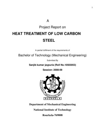
HEAT TREATMENT OF TOOL STEELThe purpose of this brochure is toprovide a general idea of how toolsteel is heat treated and how itbehaves during this process. Specialattention is paid to hardness, toughness and dimensional stability.What is tool steel?Tool steels are high-quality steelsmade to controlled chemical composition and processed to developproperties useful for working andshaping of other materials. The carbon content in tool steels may rangefrom as low as 0.1% to as high asmore than 1.6% C and many arealloyed with alloying elements such aschromium, molybdenum and vanadium.Tool steels are used for applications such as blanking and forming,plastic moulding, die casting, extrusion and forging.Alloy design, the manufacturingroute of the steel and quality heattreatment are key factors in order todevelop tools or parts with the enhanced properties that only toolsteel can offer.Benefits like durability, strength,corrosion resistance and high-temperature stability are also attractivefor other purposes than pure toolapplications. For this reason, toolsteel is a better choice than construction or engineering steel forstrategic components in the differentindustries.More advanced materials easilyresult in lower maintenance costs,lighter parts, greater precision andincreased reliability.Uddeholm has concentrated itstool steel range on high alloyed typesof steel, intended primarily for purposes such as plastic moulding, blanking and forming, die casting, extrusion, forging, wood-working industry,recycling industry and componentbusiness. Powder metallurgy (PM)steels are also included in the range.Tool steel is normally delivered inthe soft annealed condition; thismakes the material easy to machinewith cutting tools and it provides amicrostructure suitable for hardening.The soft annealed microstructureconsists of a soft matrix in whichcarbides are embedded. See picturebelow.In carbon steel, these carbides areIron carbides, while in alloyed steelthey are chromium (Cr), tungsten(W), molybdenum (Mo) or vanadium(V) carbides, depending on thecomposition of the steel. Carbidesare compounds of carbon andalloying elements and are characterized by very high hardness. Highercarbide content means a higherresistance to wear.Also non-carbide forming alloyingelements are used in tool steel, suchas cobalt (Co) and nickel (Ni) whichare dissolved in the matrix. Cobalt isnormally used to improve red hardness in high speed steels, while nickelis used to improve through-hardeningproperties and also increase thetoughness in the hardened conditions.Hardeningand temperingWhen a tool is hardened, manyfactors influence the result.Some theoretical aspectsIn soft annealed condition, most ofthe carbide-forming alloying elementsare bound up with carbon in carbides.When the steel is heated up tohardening temperature, the matrix istransformed from ferrite to austenite.This means that the Iron atomschange their position in the atomiclattice and generate a new latticewith different crystallinity. Iron atoms Possible positions forcarbon atoms2.86 AUnit cell in a ferrite crystal.Body centred cubic (BCC).3.57 AUnit cell in an austenite crystal.Face centred cubic (FCC).2.98 A20µm4Uddeholm Dievar, softannealed structure.2.85 AUnit cell in a martensite crystal.Tetragonal.
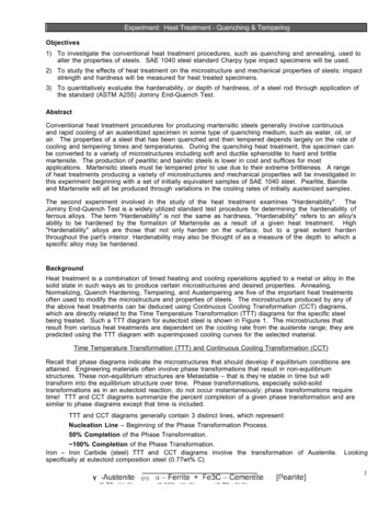
HEAT TREATMENT OF TOOL STEELAustenite has a higher solubility limitfor carbon and alloying elements, andthe carbides will dissolve into thematrix to some extent. In this waythe matrix acquires an alloying content of carbide-forming elements thatgives the hardening effect, withoutbecoming coarse grained.If the steel is quenched sufficientlyrapidly in the hardening process, thecarbon atoms do not have the timeto reposition themselves to allow thereforming of ferrite from austenite, asin for instance annealing. Instead, theyare fixed in positions where theyreally do not have enough room, andthe result is high micro-stresses thatcontribute to increased hardness.This hard structure is called martensite. Thus, martensite can be seen as aforced solution of carbon in ferrite.When the steel is hardened, thematrix is not completely convertedinto martensite. There is always someaustenite that remains in the structure and it is called retained austenite.The amount increases with increasingalloying content, higher hardeningtemperature, longer soaking timesand slower quenching.After quenching, the steel has amicrostructure consisting of martensite, retained austenite and carbides.This structure contains inherentstresses that can easily cause cracking. But this can be prevented byreheating the steel to a certain temperature, reducing the stresses andtransforming the retained austeniteto an extent that depends upon thereheating temperature. This reheatingafter hardening is called tempering.Hardening of tool steel should alwaysbe followed immediately by tempering.It should be noted that temperingat low temperatures only affects themartensite, while tempering at hightemperature also affects the retainedaustenite.After one tempering at a high temperature the microstructure consistsof tempered martensite, newlyformed martensite, some retainedaustenite and carbides.Precipitated secondary (newlyformed) carbides and newly formedmartensite can increase hardnessduring high temperature tempering.Typical of this is the so called secondary hardening of e.g. high speedsteels and high alloyed tool steels.Usually a certain hardness level isrequired for each individual application of the steel, and therefore heattreatment parameters are chosen tosome extent in order to achieve thedesired hardness. It is very importantto have in mind that hardness is theHardnessCBDATempering temperatureA martensite temperingB carbide precipitationC transformation of retained austenite tomartensiteD tempering diagram for high speed steeland high alloy tool steelA B C DThe diagram shows the influence ofdifferent factors on the secondaryhardening.It is possible to make use of differentcombinations of these factors thatwill result in the same hardness level.Each of these combinations corresponds to a different heat treatmentcycle, but certain hardness does notguarantee any specific set of properties of the material. The materialproperties are determined by itsmicrostructure and this depends onthe heat treatment cycle, and not onthe obtained hardness.Quality heat treatment delivers notonly desired hardness but also optimized properties of the material forthe chosen application.Tool steels should always be atleast double tempered. The secondtempering takes care of the newlyformed martensite during coolingafter the first tempering.Three temperings are recommended in the following cases: high speed steel with high carboncontent complex hot work tools, especiallyin the case of die casting dies big moulds for plastic applications when high dimension stability isa demand (such as in the case ofgauges or tools for integratedcircuits)result of several different factors,such as the amount of carbon in themartensitic matrix, the microstresses contained in the material, theamount of retained austenite and theprecipitated carbides during tempering.20µmUddeholm Dievar,hardened structure.5
HEAT TREATMENT OF TOOL STEELStress relievingDistortion due to hardening must betaken into account when a tool isrough machined. Rough machiningcauses thermal and mechanicalstresses that will remain embeddedin the material. This might not besignificant on a symmetrical part ofsimple design, but can be of greatimportance in an asymmetrical andcomplex machining, for example ofone half of a die casting die. Here,stress-relieving heat treatment isalways recommended.This treatment is done after roughmachining and before hardening andentails heating to 550–700 C (1020–1300 F). The material should beheated until it has achieved a uniformtemperature all the way through,where it remains 2–3 hours and thencooled slowly, for example in a furnace. The reason for a necessaryslow cooling is to avoid new stressesof thermal origin in the stress-freematerial.The idea behind stress relieving isthat the yield strength of the materialat elevated temperatures is so lowthat the material cannot resist thestresses contained in it. The yieldstrength is exceeded and thesestresses are released, resulting in agreater or lesser degree of plasticdeformation.exceptions cheaper than making dimensional adjustments during finishmachining of a hardened tool.The correct work sequence before hardening operaiton is:rough machining, stress relieving andsemi-finish machining.Heating tohardening temperatureAs has already been explained,stresses contained in the materialwill produce distortion during heattreatment. For this reason, thermalstresses during heating should beavoided.The fundamental rule for heatingto hardening temperature is therefore, that it should take place slowly,increasing just a few degrees perminute. In every heat treatment, theheating process is named ramping.The ramping for hardening should bemade in different steps, stopping theprocess at intermediate temperatures, commonly named preheatingsteps. The reason for this is to equalise the temperatures between thesurface and the centre of the part.Typically choosen preheating temperatures are 600–650 C (1100–1200 F) and 800–850 C (1450–1560 F).In the case of big tools with complexgeometry a third preheating stepclose to the fully austenitic region isrecommended.Holding time athardening temperatureIt is not possible to briefly state exactrecommendations to cover all heating situations.Factors such as furnace type, hardening temperature, the weight of thecharge in relation to the size of thefurnace, the geometry of the differentparts in the charge, etc., must betaken into consideration in each case.The use of thermocouples permitsan overview of the temperature inthe different areas of the varioustools in the charge.The ramping step finishes when thecore of the parts in the furnace reachthe chosen temperature. Then thetemperature is maintained constantfor a certain amount of time. This iscalled holding time.The generally recommended holding time is 30 minutes. In the case ofhigh speed steel, the holding time willbe shorter when the hardening temperature is over 1100 C (2000 F). Ifthe holding time is prolonged, microstructural problems like grain growthcan arise.The excuse that stress relievingtakes too much time is hardly validwhen the potential consequences areconsidered. Rectifying a part duringsemi-finish machining is with fewMPaYield strengthResidual stressescontained in the materialPlasticdeformationTemperature.The use of thermocouples gives an overview of the temperature in different areas duringheat treatment. Photo: Böhler Uddeholm Czech Republic6
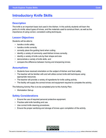
HEAT TREATMENT OF TOOL STEELQuenchingThe choice between a fast and a slowquenching rate is usually a compromise. To get the best microstructureand tool performance the quenchingrate should be rapid. To minimizedistortion, a slow quenching rate isrecommended.Slow quenching results in lesstemperature difference between thesurface and the core of a part, andsections of different thickness willhave a more uniform cooling rate.This is of great importance whenquenching through the martensiterange, below the Ms temperature.Martensite formation leads to anincrease in volume and stresses inthe material. This is also the reasonwhy quenching should be interruptedbefore room temperature has beenreached, normally at 50–70 C (120–160 F).However, if the quenching rate istoo slow, especially with heaviercross-sections, undesirable transformations in the microstructure cantake place, risking a poor tool performance.Quenching media used for alloyedsteel nowadays are: hardening oil,polymer solutions, air and inert gas.Temperaturein two steps. First it is cooled fromthe hardening temperature until thetemperature at the surface is justabove the Ms temperature. Then itmust be held there until the temperature has been equalised betweenthe surface and the core. After this,the cooling process continues. Thismethod permits the core and thesurface to transform into martensiteat more or less the same time anddiminishes thermal stresses. Stepquenching is also a possibility whenquenching in vacuum furnaces.The maximum cooling rate that canbe obtained in a part depends on theheat conductivity of the steel, thecooling capacity of the quenchingmedia and the cross-section of thepart.AC3AC1CoreSurfaceMSMartensiteThe quenching process as expressed in aCCT graph.TemperatureAir hardening is reserved for steelwith high hardenability, which in mostof the cases is due to the combinedpresence of manganese, chrome andmolybdenum.Risk of distortion and hardeningcracks can be reduced by means ofstep quenching or martempering. Inthis process the material is quenchedHardening temperatureOilAirPolymerMSVacuumSalt bathWaterRoomtemperatureTimeCooling rates for various media.TemperatureA poor quenching rate will lead tocarbide precipitation at the grainboundaries in the core of the part,and this is very detrimental to themechanical properties of the steel.Also the obtained hardness at thesurface of larger parts could be lowerfor tools with bigger cross-sectionsthan that for smaller parts, as thehigh amount of heat that has to betransported from the core throughthe surface produces a self-temperingeffect.AC3AC1Batch prepared for heat treatment.Photo: Böhler Uddeholm Czech Republic.CoreIt is still possible to find some heattreatment shops that use salt baths,but this technique is disappearing dueto environmental aspects.Oil and polymer solutions areusually utilised for low alloyed steeland for tool steel with low carboncontents.SurfaceMSMartensiteTimeMartempering or step-quenching.7
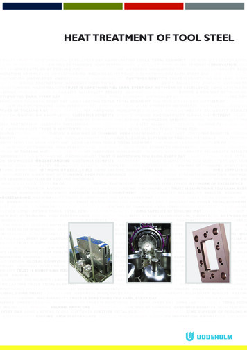
HEAT TREATMENT OF TOOL STEELSOME PRACTICAL ISSUESVACUUM TECHNOLOGYAt high temperature, steel is verylikely to suffer oxidation and variations in the carbon content (carburization or decarburization). Protectedatmospheres and vacuum technologyare the answer to these problems.Decarburization results in low surface hardness and a risk of cracking.Carburization, on the other hand,can result in two different problems: the first and easiest to identify isthe formation of a harder surfacelayer, which can have negativeeffects the second possible problem isretained austenite at the surfaceVacuum technology is the most usedtechnology nowadays for hardeningof high alloyed steel.Vacuum heat treatment is a cleanprocess, so the parts do not need tobe cleaned afterwards. It also offers areliable process control with highautomation, low maintenance andenvironmental friendliness. All thesefactors make vacuum technologyespecially attractive for high-qualityparts.Top gas flapRetained austenite can in many casesbe confused with ferrite when observing it through the optical microscope. These two phases also havesimilar hardness, and therefore, whatat first sight can be identified as adecarburization can in some cases be When the furnace reaches a temperature of approx. 850 C (1560 F),the effect of radiation heatingmechanisms will overshadow that ofthe convection ones in the heattransfer process. Therefore theNitrogen pressure is lowered, inorder to optimize the effects ofradiation and convection heatingmechanisms are negligible underthese new physical conditions. Thenew value of the nitrogen pressureis around 7 mbar. The reason forhaving this remaining pressure is toavoid sublimation of the alloyingHeating elementsHeat exchangerFurnacevesselBottom gas flapCooling fanHot zoneConvection fanCooling phase, top cooling. Illustration from Schmetz GmbH Vacuum Furnaces, Germany.Batch type furnace with controlledatmosphere. Photo: Bodycote Stockholm,Sweden.the completely opposite problem.For these reasons it is very important that the atmosphere in whichthe heat treatment takes place doesnot affect the carbon content of thepart.Wrapping in a hermetically closedstainless-steel foil also provides someprotection when heating in a mufflefurnace. The steel foil should be removed before quenching.The different steps in the functioningof a vacuum furnace can schematicallybe listed as follows: When the furnace is closed aftercharging operation, air is pumpedout from the heating chamber inorder to avoid oxidation. An inert gas (most commonlyNitrogen) is injected into the heating chamber until a pressure ofaround 1–1.5 bar is reached.elements, i.e. to avoid the loss ofalloying elements to the vacuum.This low pressure condition will bemaintained invariant during the lastpart of the heating process, as wellas during the holding time at thechosen hardening temperature. The cooling down will be carriedout by a massive injection of inertgas (most commonly nitrogen)into the heating chamber in alter- The heating system is started.The presence of the inert gas willmake possible the heat transferprocess through convection mechanisms. This is the most efficient wayto heat up the furnace to a temperature of approx. 850 C(1560 F).Hot zone with graphite insulation. Photo:Schmetz GmbH Vacuum Furnaces, Germany.8
HEAT TREATMENT OF TOOL STEELVertical coolingFrom top to bottomFrom bottom to topHorizontal coolingFrom right to leftFrom left to rightCooling phase. Nitrogen gas stream passes through the heating chamber in differentdirections. Illustration from Schmetz GmbH Vacuum Furnaces, Germany.nating directions and reaching theoverpressure that was previouslychosen when programming thefurnace. The maximum overpressure is a nominal characteristicof each furnace and it gives an ideaof its cooling capacity.Charging operation. Photo: Böhler Uddeholm Czech Republic.Vacuum furnace. Photo: Schmetz GmbHVacuum Furnaces, Germany.9
HEAT TREATMENT OF TOOL STEELTemperingThe material should be temperedimmediately after quenching.Quenching should be stopped at atemperature of 50–70 C (120–160 F)and tempering should be done atonce. If this is not possible, thematerial must be kept warm, e.g. in aspecial “hot cabinet” awaiting tempering.Please, notice that the stressescontained in the as-quenchedmaterial can result in breakageof the crystalline structure andthe formation of cracks if thetempering is not done immediately after the quenching process. This breakage of the crystalline structure can take placein a violent way. Therefore theimportance of tempering assoon as possible is not only tosafeguard the part from cracks,but it is also a matter of personal safety.Uddeholm has made a wide range ofexperiments and measurements andcollected the resulting data regarding hardness, toughness, dimensionalchanges and retained austenite ingraphs. These graphs are available forthe different steel grades and are ofgreat help in order to choose thecorrect tempering temperature.The first priority when choosingthe tempering temperature should bethe mechanical properties, as somesmall dimensional adjustments can bemade in a last fine machining step.The mechanical and physical properties obtained after tempering willdepend greatly on the chosen tempering temperature. High-temperature tempering will result in a lowercontent of retained austenite thanlow-temperature tempering. Thematerial will therefore have highercompressive strength and improveddimensional stability (in service andat surface coating).When tempering at high temperature, other differences in propertiesare also noticeable, like higher heatconductivity.10Precipitation of secondary carbideswill occur when tempering highlyalloyed steel at a high temperature.This will be detrimental to its corrosion resistance but will give to itsomewhat higher wear resistance. Ifthe tool is to be electrical dischargemachined (EDM) or coated, hightemperature tempering is necessary.HOW MANY TEMPERSARE REQUIRED?Two tempers are generally recommended for tool steel, except in thecases of large cross-sections, partswith complex geometries or veryhigh demands on dimensional stability. In these cases, a third temperingis usually needed.The basic rule of quenching is tointerrupt at 50–70 C (120–160 F).Therefore a certain amount of austenite remains untransformed when thematerial is ready to be tempered.When the material cools after tempering, most of the austenite is transformed to newly formed martensite(untempered). A second temperinggives the material optimum toughness at the chosen hardness level.HOLDING TIMESIN CONNECTION WITHTEMPERINGHere there is also a general rule,applicable in most of the cases: oncethe tool has been heated through,hold it for at least two hours at fulltemperature each time.AusteniteUntempered martensiteTempered hingAfter firsttemperingAfter secondtemperingAfter thirdtempering**HSS steel and big high-pressure die casting diesEvolution of the phasecontent along thedifferent steps of theheat treatment.A lower die foraluminium rim justbefore heat treatmenton charging grid.Photo: ASSAB Çelik(Turkey)
HEAT TREATMENT OF TOOL STEELDimensional andshape stabilityDistortion duringhardening and tempering oftool steelWhen a piece of tool steel is hardened and tempered, some warpageor distortion normally occurs. This iswell known and it is normal practiceto leave some machining allowanceon the tool prior to hardening, making it possible to adjust the tool tothe correct dimensions after hardening and tempering by grinding, forexample .How does distortiontake place?The cause is stresses in the material.These stresses can be divided into: machining stresses thermal stresses transformation stressesIn order to reduce distortion whileheating during the hardening process,a stress relieving operation should becarried out prior to the hardeningoperation. It is recommended tostress relieve the material after roughmachining. Any distortion can then beadjusted during semi-finish machiningprior to hardening operation.THERMAL STRESSESThermal stresses arise every timethere is a temperature gradient in thematerial, i.e. when the temperature isnot even all over the part.Thermal stresses grow with increasing heating rate. Uneven heatingcan result in local variations in volume due to uneven dilatation ratesand this will also contribute to thearising of stresses and distortion.In order to tackle this problem, itis common practice to heat up thematerial in steps, in order to equalisethe temperature between the surfaceand the centre.MACHINING STRESSESMachining stresses are generatedduring machining operations such asturning, milling and grinding or anytype of cold working.If stresses have built up in a part,they will be released during heating.Heating reduces strength, releasingstresses through local distortion. Thiscan lead to overall distortion.Yield strength Rp0.2MPa40035030025020015010050100 200 300 400 500 600 C210 390 570 750 930 1110 FTemperatureEffect of temperature on the yieldstrength of Uddeholm Orvar Supreme,soft annealed.thermal stresses. But as earlier mentioned, a faster quenching will resultin better mechanical properties.It is important that the quenchingmedium is applied as uniformly aspossible. This is especially valid whenforced air or protective gas atmosphere (as in vacuum furnaces) is used.Otherwise temperature differencesin the tool can lead to significantdistortion.Linear expansion mm/100 mm0.80.6TRANSFORMATION STRESSESTransformation stresses arise whenthe microstructure of the steel istransformed. This is because thethree phases in question —ferrite,austenite and martensite—havedifferent densities, i.e. volumes.Out of all the microstructuralchanges that take place during heattreatment, the biggest contributionto transformation stresses is causedby the transformation of austeniteinto martensite. This causes a volumeincrease.Excessively rapid and unevenquenching can also cause local martensite formation and thereby volume increases locally in a piece andgives rise to stresses in this section.These stresses can lead to distortionand, in some cases, hardening cracks.0.4Volume0.2100210200 300 400 500 600 C390 570 750 930 1110 FTemperatureEffect of temperature on the linear expansion of Uddeholm ORVAR Supreme, softannealed.An attempt should always be made toheat slowly enough so that the temperature remains virtually equalthroughout the piece.What has been said regardingheating, applies also to cooling.Very powerful stresses arise duringquenching. As a general rule, theslower quenching can be done, theless distortion will occur due toTransformationto martensite MsTransformationto austeniteAC1AC3TemperatureVolume changes due to structuraltransformation.11
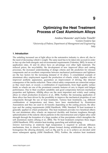
HEAT TREATMENT OF TOOL STEELHow can distortionbe reduced?SUB-ZERO TREATMENTDistortion can be minimized by: keeping the design simple andsymmetrical eliminating machining stressesby stress relieving after roughmachining heating up slowly to hardeningtemperature using a suitable grade of steel quenching the piece as slowly aspossible, but quick enough toobtain a correct microstructurein the steel by usage of martempering or stepquenching tempering at a suitable temperatureThe following values for machiningallowances can be used as guidelines.UddeholmSteel gradeMachining allowanceon length and diameteras % of SLEIPNERSVERKER 3SVERKER 21VANADIS 4 EXTRAVANADIS 6VANADIS 10VANADIS 23VANCRON 40CORRAXELMAXMIRRAX ESRSTAVAX ESRUNIMAXALVARALVAR 14DIEVARHOTVARORVAR 2 MICRODIZEDORVAR SUPREMEQRO 90 SUPREMEVIDAR SUPERIORBURE0,25 %0,25 %0,20 %0,20 %0,20 %0,25 %0,20 %0,20 %0,15 %0,15 %0,15 %0,15 %0,20 %0,05–0,15 %*0,15 %0,20 %0,15 %0,30 %0.20 %0.20 %0,30 %0,30 %0,20 %0,20 %0,30 %0,25 %0.20 %* Depending on ageing temperature12Retained austenite in a tool cantransform into martensite duringservice. This will lead to local distortion and embrittlement of the tooldue to the presence of untemperedmartensite. Therefore the requirement of maximum dimensional stability in service has an implied demandfor very low or no retained austenitecontent. This can be achieved byusing sub-zero treatment afterquenching or by high temperaturetempering.The sub-zero treatment leads toa reduction of retained austenitecontent by exposing the tool or partto very low temperatures. The mostcommonly used are about -80 C(-110 F) and -196 C (-320 F). This, inturn, will result in a hardness increase of up to 1–2 HRC, in comparison to non sub-zero treatedtools, if low temperature temperingis used. For high temperature tempered tools there will be little or nohardness increase.Tools that are high temperaturetempered, even without a sub-zerotreatment, will normally have a lowretained austenite content and inmost cases, a sufficient dimensionalstability. However, for high demandson dimensional stability in service itis also recommended to use a subzero treatment in combination withhigh temperature tempering.For the highest requirements ondimensional stability, sub-zero treatment in liquid nitrogen is recommended after quenching and aftereach tempering. Always finish with atempering as last operation, in orderto avoid the existence of untemperedmartensite in the part.Surface treatmentNitridingNitriding is performed by exposingthe parts to some media rich innitrogen under certain physical conditions that will result in the diffusionof nitrogen atoms into the steel andthe formation of nitrides. The partsurface will then be harder and havea higher wear resistance in its outerlayer.In the case of corrosion resistantsteel with high-chromium content, itis very important to take into consideration the fact that nitriding has adetrimental effect on the corrosionresistance of the material. In othercases nitriding can have a positiveeffect on the corrosion resistance.Appropriate steel to be nitridedare usually medium-carbon steelwith nitride-forming elements suchas chromium, aluminium, molybdenum and vanadium.The core should act as a stablesubstrate regarding mechanical properties and microstructure. Thismeans that for hardened material itis necessary to temper above thenitriding temperature in order toavoid softening of the core duringthe nitriding process.It should be noted that a nitridedsurface cannot be machined withNo treatmentSub-zero treatmentRetained austenite %Hardness HRC247521Hardness70186515601255950Retained austenite64534035150250350450550650 C30048066084010201200 FTempering temperature CUddeholm Sleipner.Hardness and retainedaustenite as function oftempering temperaturewith and without sub-zerotreatment.
HEAT TREATMENT OF TOOL STEELcutting tools and can only be groundwith difficulty. A nitrided surface willcause problems in weld repairing aswell.There are several technologiesavailable in the field of nitriding; themain ones are gas nitriding, high pressure nitriding (carried out in vacuumfurnaces) and plasma nitriding.Two common problems of conventional nitriding technologies
HEAT TREATMENT OF TOOL STEEL 4 Uddeholm Dievar, soft annealed structure. The purpose of this brochure is to provide a general idea of how tool steel is heat treated and how it behaves during this process. Special attention is paid to hardness, tough-ness and dimensional stability. What is tool steel? To ol steels are high-quality steels