Transcription
emDesign and ControlSYS-APM001-EN (March 2001)
Multiple-Chiller-SystemDesign and ControlMick Schwedler, applications engineerAnn Yates, information designer
PrefaceThis manual examines chilled-water-system components, configurations,options, and control strategies. The goal is to provide system designers withoptions they can use to satisfy the building owners’ desires, but this manual isnot intended to be a complete chiller-system design manual.System designers may get the most use from this manual by familiarizingthemselves with chilled-water-system basics and understanding the benefits ofvarious options. Thereafter, when a specific job will benefit from theseadvantages, consult appropriate sections of the manual in detail.The Engineers Newsletters that are referenced in this manual are available pThe Trane Company, in proposing these system design and applicationconcepts, assumes no responsibility for the performance or desirability of anyresulting system design. System design is the prerogative and responsibility ofthe system designer.SYS-APM001-EN 2001 American Standard Inc. All rights reserved
ContentsIntroduction . 1Chilled-Water-Plant Basics . 2Chiller.2Loads .5Chilled-water distribution system .7Condenser-water system .10Controls .11Chilled-Water-System Options . 13Chilled- and condenser-water temperatures .13Chilled- and condenser-water flow rates .15Misconceptions about low-flow rates .24System Configurations . 27Parallel chillers .27Series chillers .29Primary–secondary (decoupled) systems .31Pumping Arrangements . 36Flow-based control .38Chiller sequencing .39Variable-Primary-Flow Systems . 40VPF advantages .41VPF caveats .41Chiller sequencing .43Chilled-Water-Control Options . 47Chilled-water reset—raising and lowering .47Critical valve reset .48Design Considerations . 49Chilled-water pump configurations.49Bypass line sizing.50Amount of fluid in the loop .50Plant expansion.51SYS-APM001-ENiii
ContentsChilled-Water- System Variations . 54Heat recovery . 54Preferential loading .54Unequal chiller sizing . 58Series-counterflow application.58Applications outside the chiller’s range .60Chilled-Water-System Issues . 63Low T syndrome . 63Check valve in the bypass line. 63Failure recovery .64Alternative energy sources .64Contingency .66Condenser-System Variations . 69Condenser flow configurations .69Cooling-tower-fan control methods .71Plate-and-frame heat exchanger . 72Well, river, or lake water .72Condenser-water temperature control .72Condenser-water pump options .73Retrofit opportunities . 75Conclusion . 78Glossary . 79References . 82Index . 85ivSYS-APM001-EN
ContentsFiguresFigure 1Figure 2Figure 3Figure 4Figure 5Figure 6Figure 7Figure 8Figure 9Figure 10Figure 11Figure 12Figure 13Figure 14Figure 15Figure 16Figure 17Figure 18Figure 19Figure 20Figure 21Figure 22Figure 23Figure 23aFigure 24Figure 25Figure 26Figure 27Figure 28Figure 29Figure 30Figure 31SYS-APM001-ENTypical vapor-compression chiller. 2Valve-controlled loads . 6Uncontrolled coil. 7Simplified distribution system. 9Chilled-water-system performance at part load. 19Annual system operating costs . 23System energy comparison (no pipe) . 25Parallel chillers with single, common pump . 27Parallel chillers with separate, dedicated chiller pumps . 28Series chillers . 29Decoupled arrangement. 31Production loop. 33Distribution loop . 34Campus pumping arrangement . 36Tertiary pumping arrangement. 37Decoupled system supply tee . 37Temperature-sensing. 38Variable-primary-flow system. 40Double-ended decoupled system . 53Parallel preferential loading arrangement . 55Sidestream preferential loading arrangement . 56Plate-and-frame heat exchanger . 57Series-counterflow arrangement. 59Equal lift concept . 59Flow rate out of range for equipment . 60Temperatures out of range for equipment . 61Precise temperature control, multiple chillers . 62Failure recovery . 64Manifolded condenser-water pumps . 69Chiller-tower energy consumption. 73Decoupled condenser-water system . 74Chiller-tower selection with different chiller capacities . 76v
ContentsTablesTable 1Table 2Table 3Table 4Table 5Table 6Table 7Table 8Table 9Table 10Table 11viRecommended chiller-monitoring points perASHRAE Guideline 3-1996 .11Standard rating conditions for absorption chillers.15Standard rating conditions for chilled-water systems .16Low-flow conditions for chilled-water pump . 17Low-flow conditions for cooling tower.17Low-flow conditions for condenser-water pump.17Total system power .18Effect of decreased water temperature .20Retrofit capacity changes. 21Reduced flow-rate effect .24Flow-rate-fluctuation examples.44SYS-APM001-EN
IntroductionMany building owners continually search for solutions that allow theirbusinesses to offer higher quality, and to be more competitive and profitable.HVAC systems designers often use chilled-water systems to provide highquality, cost-effective air conditioning for building owners. With the advent ofmore flexible chillers, system-level controls, and software analysis tools, thenumber of chilled-water-systems options has exploded.SYS-APM001-EN1
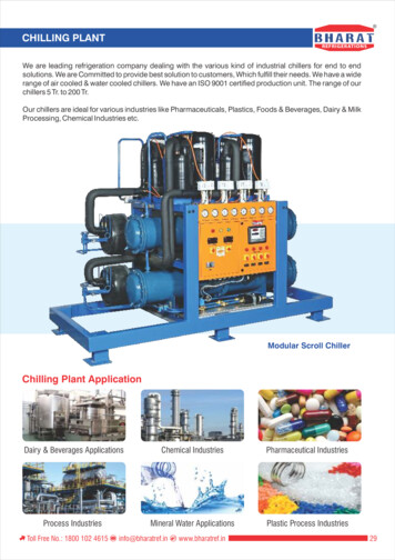
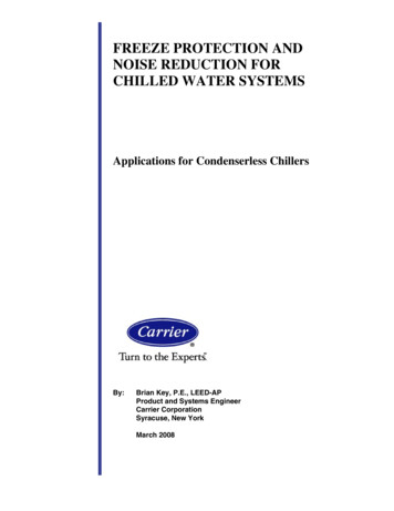
Chilled-Water-Plant BasicsChilled-water plants consist of these functional parts:nnnnnChillers that produce chilled waterLoads, often satisfied by coils, that transfer heat from air to waterChilled-water distribution pumps and pipes that send chilled water to thepreviously mentioned loadsCondenser-water pumps, pipes, and cooling towers that reject heat(for water-cooled chillers)Controls that coordinate the operation of the mechanical componentstogether as a systemChillerThere are a variety of water chiller types. Most commonly, they are absorption,centrifugal, helical rotary, and scroll. Some reciprocating chillers are alsoavailable. Chillers can be either air- or water-cooled. Major vapor-compressionchiller components include an evaporator, a compressor(s), a condenser, andan expansion device(s). This manual discusses the chiller’s evaporator andcondenser and their relationship to the chilled-water plant.Figure 1Typical vapor-compression chillerCompressorCondenserEvaporator2SYS-APM001-EN
Chilled-Water-Plant BasicsEvaporatorThe evaporator section of a water chiller is a shell-and-tube, refrigerant-towater heat exchanger. Depending on the chiller’s design, either the refrigerantor the water is contained within the tubes.nnIn a flooded shell-and-tube evaporator, cool, liquid refrigerant at lowpressure enters the distribution system inside the shell and movesuniformly over the tubes, absorbing heat from warmer water that flowsthrough the tubes.In a direct-expansion (DX) shell-and-tube evaporator, warmer water fills theshell while the cool, lower-pressure liquid refrigerant flows through thetubes.In either design, there is an approach temperature, which is the temperaturedifference between the refrigerant and exit water stream. The approachtemperature is a measure of the heat transfer efficiency of the evaporator.Effect of chilled-water temperatureFor a given chiller, as the leaving chilled-water temperature drops, therefrigerant temperature and pressure must also drop. Conversely, as theleaving chilled-water temperature rises, so do the refrigerant temperature andpressure. When the leaving chilled-water temperature changes, the work acompressor must do also changes. The effect of leaving chilled-watertemperature change on power consumption can be 1.0 percent to 2.2 percentper degree fahrenheit [1.8 percent to 4.0 percent per degree celsius]. Alwaysconsider the energy consumption of the entire system—not only the chiller. It isimportant to remember that although reducing leaving chilled-watertemperature penalizes the chiller, it may benefit the pumps because less wateris pumped through the system. System interactions are covered in more detailin the next section Chilled-Water-System Options.Effect of chilled-water flow rateSince the evaporator is a heat exchanger, it is sensitive to water flow rate.Excessive flow may result in high water velocity, erosion, vibration, or noise.Insufficient flow reduces heat-transfer efficiency and causes poor chillerperformance. Some designers have concerns over low flow rates causing3fouling. Generally, as Webb and Li noted, these concerns are unwarrantedsince the chilled-water loop is a closed system, thus reducing the chances ofmaterials entering the system and causing fouling. Chilled-water flow throughthe chiller must be kept within specific minimum and maximum limits. Contactthe manufacturer for these limits.SYS-APM001-EN3
Chilled-Water-Plant BasicsSome chiller controls can accommodate very little flow variation duringmachine operation.2 Other, more sophisticated, chiller controls allow someflow variation. Some chillers can tolerate flow-rate variations of as much as 30percent per minute or greater, while others can only tolerate up to 2 percent perminute. It is important that chiller capabilities are matched to systemrequirements. Contact the chiller manufacturer to determine allowable rate offlow variation before varying the flow through the evaporator in a chiller. Flowvariation is discussed in detail in the section Variable-Primary-Flow Systems,page 40.Water-cooled condenserTo cool a building or process, the transferred heat must ultimately be rejected.The total amount of heat rejected includes the sum total of the evaporator load,the compressor work, and the motor inefficiency. In a hermetic chiller, wherethe motor and compressor are in the same housing, these loads are all rejectedthrough the condenser. In an open chiller, where the motor is separate from thecompressor and connected by a shaft, the motor heat is rejected directly to thesurrounding air. The evaporator load and the compressor work are rejectedthrough the condenser and the motor heat must be taken care of by the airconditioning system.Effect of condenser-water temperatureFor a given chiller, as the leaving condenser-water temperature rises,refrigerant temperature and pressure also rise. Conversely, as leavingcondenser-water temperature drops, so do refrigerant temperature andpressure. As the refrigerant pressure and temperature changes, the work acompressor must do also changes. The effect of leaving-condenser-watertemperature change on power consumption can be 1.0 percent to 2.2 percentper degree fahrenheit [1.8 percent to 4.0 per degree celsius]. Always considerthe energy consumption of the entire system—not just the chiller. It isimportant to remember that although raising the leaving condenser-watertemperature penalizes the chiller, it may benefit the pumps and cooling towerthrough the use of reduced flow rates and higher thermal driving-forces on thetower. System interactions are covered in more detail in the section CondenserSystem Variations, page 69.Effect of condenser-water flow rateSince the condenser is a heat exchanger, it is sensitive to water flow rate. Forexample, excessive flow may result in high water velocity, erosion, vibration, ornoise, while insufficient flow reduces heat transfer efficiency and causes poorchiller performance. Therefore, condenser-water flow through the chiller shouldbe kept within a specific range of limits, except during transient startup4SYS-APM001-EN
Chilled-Water-Plant Basicsconditions. Contact the manufacturer for these limits. Some chillers may allowextended operation below the selected flow rates.If water velocity through the condenser tubes is too low for significant periodsof time and the water is extremely hard, long-term fouling of the tubes mayalso occur. Webb and Li3 tested a number of internally-enhanced condensertubes at low velocity (3.51 ft/s [1.07 m/s]) and high water hardness. While theyfound that some of the internally-enhanced tubes fouled, in the long term theyconcluded:Because of the high hardness and low water velocity used in thesetests, we do not believe that the fouling experienced is typical of thatexpected in commercial installations. With use of good maintenancepractices and water quality control, all of the tubes tested are probablysuitable for long-term-fouling applications.It is important to remember that a chiller selected for low flow (as discussed inthe next section Chilled-Water-System Options) does not necessarily have lowvelocity through its tubes. If tube fouling is a major concern, consider the use ofsmooth, rather than internally-enhanced, tubes in the condenser for ease ofcleaning.Air-cooled condenserObviously, air-cooled chillers do not use condenser-water, since they reject theirheat by having ambient air passed across refrigerant-to-air heat exchangers. Inpackaged air-cooled chillers, the manufacturers attempt to provide optimalperformance by staging fans in response to chiller load and ambient, dry-bulbtemperature.LoadsIn comfort-cooling applications, loads are usually satisfied by air handlersequipped with coils to transfer heat from conditioned space air to circulatingchilled-water. Air is thus cooled and dehumidified as it passes across the finnedsurface of the cooling coils. Since the psychrometric process of conditioning airtakes place at the coils, selection of the optimum coil size and type from thewide variety available is important for proper system performance.SYS-APM001-EN5
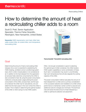
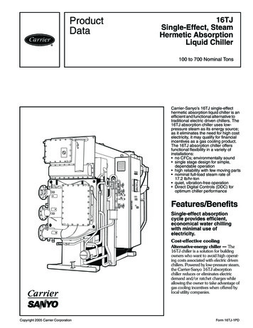
Chilled-Water-Plant BasicsSome specialized process loads do not involve cooling air. Instead, they mayinvolve heat transfer directly within a piece of process equipment, such as thecooling jacket of an injection-molding machine. Heat transferred from the loadscan be controlled in a number of ways:nnnnThree-way valveTwo-way valveVariable-speed pumpUncontrolled coilsThree-way valve load controlA three-way control valve regulates the amount of water passing through a coilin response to loads. The valve bypasses unused water around the coil andrequires a constant flow of water in the system, regardless of load. A drawbackof this bypass is that the temperature of the water leaving the three-way valveis reduced at part-load conditions. This can be a major cause of so-called “low T syndrome” discussed on page 63 in the section Chilled-Water-SystemIssues. Three-way valves are used in many existing systems.Figure 2Valve-controlled loadsThree-Way ValveCooled AirTwo-Way ValveCooled AirTwo-way valve load controlA two-way, water modulating valve at the coil performs the same waterthrottling function as the three-way valve. The coil sees no difference betweenthese two methods. The chilled-water system, however, sees a great difference.In the case of the two-way valve, all flow in the coil circuit is throttled. No wateris bypassed. Consequently, a system using two-way valves is a variable-flowchilled-water system. The temperature of the water leaving the coil is notdiluted by bypass water so at part-load conditions, the system return-watertemperature is higher than with three-way valve control.6SYS-APM001-EN
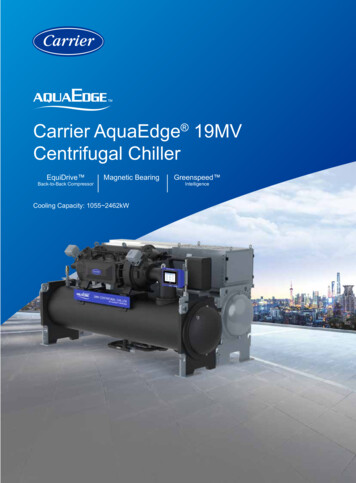
Chilled-Water-Plant BasicsVariable-speed pumping load controlBy using a pump for each coil, the flow may be controlled by varying the pumpspeed. In such systems, there may be no control valves at the coil. This canreduce both the valve and the valve installation costs.Uncontrolled coilsFigure 3 shows a control variation using an uncontrolled or “wild”coil. In thissystem, control of the conditioned air supply is executed by face-and-bypassdampers that permit a portion of the air to bypass the coil surface. Advantagesof the strategy are the elimination of control valves and improved part-loaddehumidification. A disadvantage is that all the water is pumped all the time;however, in systems with very small water pressure drops, this systemarrangement may work economically.Figure 3Uncontrolled coilBypass DamperAir HandlerCooled Air MixtureFace DamperChilled-water distribution systemChilled water is circulated through fixed piping—most commonly steel, copper,or plastic—that connects the chiller with various load terminals. Piping is sizedto meet a project’s pressure loss, water velocity, and construction costparameters. Pressure drop is overcome by the use of a chilled-water pump.SYS-APM001-EN7
Chilled-Water-Plant BasicsChilled-water pumpThe purpose of the chilled-water pump is to circulate chilled water within theloop. Generally, the pump must overcome the frictional pressure losses causedby the piping, coils, and chiller and the pressure differential across open controlvalves in the system. The pump, while working at the system static pressure,does not need to overcome this static pressure. For example, in a forty-storybuilding the pump need not overcome the static pressure due to those fortystories.The pump is typically located upstream of the chiller, however it may beanywhere in the system, provided that the pump:nnnmeets the minimum pump net positive suction-head requirements. That is,the system pressure at the pump inlet must be both positive and highenough to allow the pump to operate properly;maintains the minimum dynamic pressure head at critical systemcomponents (usually the chiller). If the dynamic pressure head is not highenough at these components, proper flow will not be established throughthem;accommodates the total pressure (static head plus dynamic head) onsystem components such as the chiller’s evaporator, valves, etc.Note that the pump heat is added to the water and must be absorbed by thechiller. Generally, this represents a very small temperature increase.Multiple pumps are often used for redundancy. Depending on the terminalcontrol devices and system configurations, the chilled-water pumps may beeither constant or variable-flow.8SYS-APM001-EN
Chilled-Water-Plant BasicsDistribution pipingBy itself, the distribution system is easy to understand. Figure 4 shows asimplified distribution system consisting of multiple cooling coils, eachcontrolled by a thermostat that regulates the flow in its respective coil. Thevalves may be either three-way or two-way. As previously discussed, three-wayvalves require constant water flow, while two-way valves allow the water flowin the system to vary. As flow varies, the pump may simply ride its curve or usea method of flow control such as a variable-speed drive. See the section SystemConfigurations, on page 27, for a detailed discussion of distribution-systemoptions.Figure 4Simplified distribution ads2000 ASHRAE HVAC Systems andEquipment Handbook, Chapter 12,Hydronic Heating and Cooling System1Design contains additional referenceinformation on the components of achilled water distribution system.SYS-APM001-ENThe distribution system may contain other components, such as an expansiontank, control valves, balancing valves, check valves, and an air separator, toname a few. The density, and therefore the volume, of the water in a “closed”chilled-water distribution system varies as it undergoes changes intemperature. The expansion tank allows for this expansion and contraction ofwater volume.9
Chilled-Water-Plant BasicsCondenser-water systemAs in chilled-water distribution systems, condenser-water system piping—mostcommonly steel, copper, or plastic—is sized to meet a project’s operatingpressure, pressure loss, water velocity, and construction cost parameters.Pressure drop through piping and the chiller’s condenser, plus the coolingtower static lift, is overcome by use of a condenser-water pump.Cooling towerTo reject heat, water is passed through a cooling tower where a portion of itevaporates, thus cooling the remaining water. A particular cooling tower’seffectiveness at transferring heat depends on water flow rate, watertemperature, and ambient wet bulb. The temperature difference between thewater entering and leaving the cooling tower is the range. The temperaturedifference between the leaving water temperature and the entering wet-bulbtemperature is the approach.Effect of loadAs the building load—or heat rejection—decreases, range and approach alsodecrease. This means that when the building is at part load, the cooling towercan provide colder water at the same ambient wet-bulb temperature.Effect of ambient conditionsAs ambient wet-bulb temperature drops, the approach—at a constant load—increases. This must be considered when cooling-tower-control strategies aredeveloped. Detailed descriptions of these conditions appear in the subsection,Chiller-tower energy balance, page 72. For additional information, refer to 2000ASHRAE HVAC Systems and Equipment Handbook, Chapter 36, “CoolingTowers.”110SYS-APM001-EN
Chilled-Water-Plant BasicsControlsThe chilled-water supply temperature is usually controlled at the chiller. Mostcommonly, supply water temperature is used as the sensed variable to permitcontrol of chiller capacity to meet system load demand. Supply-temperaturecontrol strategies may be used on either constant- or variable-flow systems. Aspreviously discussed, flow control is executed at the load terminals using threeway or two-way valves, or separate pumps for each coil.Control capabilities run the gamut from slow-acting pneumatic controls, toelectromechanical controls, to sophisticated digital controls that use algorithmstuned to give superior performance.Chiller controlToday’s chiller controls are capable of doing more than simply turning thechiller on and off. At a minimum, these controls should monitor:nnnSafety points such as bearing temperatures and electrical points that, whenout of range, may cause motor failure.Data points that may cause operational problems if corrective action is nottaken. An example is low chilled-water or refrigerant temperature, whichmay result in freezing in or around the evaporator tubes.General points that should be logged daily to ensure proper chillerperformance.Table 1 lists the ASHRAE-recommended monitoring points.Table 1 Recommended chiller-monitoring points per ASHRAE Guideline 3-1996FlowChilledWaterInlet PressureInlet TemperatureFlowCondenser Inlet PressureWaterInlet TemperatureOutlet PressureOutlet PressureOutlet TemperatureOutlet TemperatureApproach TemperatureEvaporatorOilRefrigerant PressureRefrigerant PressureRefrigerant TemperatureRefrigerant TemperatureLevelLevelPressureTemperatureAdditional RequiredSYS-APM001-ENApproach TemperatureCondenserRefrigerant Compressor Discharge TemperatureAdditional RequiredVibration Levels11
Chilled-Water-Plant BasicsIn addition to monitoring data, it is vital that the chiller controls alert operatorsto possible problems. Diagnostic messages are necessary for the operator torespond to safety issues and data points that are outside normal operatingranges.While communicating these diagnostic messages is a requirement, some chillercontrols include factory-installed programming that responds to the diagnosticmessages. For example, when the chilled-water temperature nears freezing, thechiller sends a diagnostic message and adapts its operation by reducing thecompressor capacity, raising the chilled-water temperature to a safer condition.Finally, the chiller controls should communicate with a system-level controller.There are many system aspects that are outside the chiller’s direct control, suchas condenser-water temperature and the amount of fluid flowing through theevaporator and condenser. To minimize the system energy costs, the systemcontrols must coordinate chiller, pump, cooling-tower, and terminal-unitcontrols. This can only be done if adequate information is communicated fromeach system component to the system-level controls.Pump controlIn so-called constant flow systems, the pumps are either on or off, providingrelatively constant flow when in the on position. In practice, some flowvariation will occur as system pressure drop changes. In a variable-flow system,pump control is most often performed by maintaining a pressure differential ata selected point in the system. For example, a variable-speed drive will increaseits speed if the sensed pressure differential is too low, or slow down if thepressure differential is too high. The control point is selected to minimize overpressuring the system and to assure adequate flow at all critical loads. Optimalpumping control strategies are addressed in Critical valve reset, page 48.Chapter references1 2000 ASHRAE HVAC Systems and Equipment Handbook, Chapter 12,Hydronic Heating and Cooling System Design and Chapter 36, CoolingTowers, American
HVAC systems designers often use chilled-water systems to provide high- quality, cost-effective air conditioning for building owners. With the advent of more flexible chillers, system-level controls, and software analysis tools, the number of chilled-water-systems options has exploded.