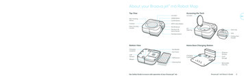
Transcription
DX100 Robot ControllerFunctional Safety UnitTraining ManualNOT FOR RESALE 2010 by MOTOMANAll Rights ReservedFirst Edition April 30, 2013Yaskawa America, Inc.MOTOMAN Robotics Division100 Automation WayMiamisburg, OH 45342TEL: (937) 847-6200FAX: (937) 847-627724-HOUR HOTLINE: (937) 847-3200www.motoman.com
PREFACEPURPOSE OF THIS MANUALMOTOMAN TECHNICAL EDUCATION CENTER training manuals are not intended for useas stand alone training tools. This manual is to be used in conjunction withthe DX Functional Safety Unit course.WHO SHOULD USE THIS MANUALThis manual is only issued to attendees of the DX Functional Safety Unitcourse. Do not use the manual as a reference tool unless you have attendedthe course and received certification through MOTOMAN TECHNICAL EDUCATIONCENTER.HOW TO USE THIS MANUALThis training manual has been written according to the daily structure ofthe DX Functional Safety Unit course. It is designed to assist students inunderstanding the DX Functional Safety Unit for the DX100 controller and aMOTOMAN robot. Use this manual as a step-by-step guide through the course.DISCLAIMERInformation in this manual is based on the assumption that the DX100controller is in the MANAGEMENT Security Level and is using theExpanded Language. Be aware that the keystrokes described in this manualmay vary based on other settings, software versions, and options.NOTE:This manual is not for resale and will not be sold separately.All training manuals developed by MOTOMAN TECHNICAL EDUCATION CENTERare copyrighted. Do not copy any portion of these manuals.
TABLE OF CONTENTS1.0 SAFETY RANGE FUNCTION FOR ROBOT . 1-11.1Changing Security Mode . 1-11.2Preparation for Safety Range Function . 1-21.3Setting Tool Interference File . 1-21.4Setting Safety Range for Robot . 1-61.5Confirming Safety Range for Robot . 1-111.6Starting Safety Range Function for Robot . 1-111.7Confirming Safety Range and Robot Position . 1-132.0 SAFETY RANGE SWITCHING FUNCTION . 2-12.1Function Outline . 2-12.2Wiring Method for Range Switching Function . 2-22.3Switching Safety Range . 2-32.4Robot Operating Range Data . 2-43.0 SAFETY RANGE FUNCTION FOR EACH AXIS . 3-13.1Preparation for Safety Range Function . 3-13.2Setting Safety Range for Each Axis. 3-13.3Confirming Safety Range for Each Axis . 3-43.4Starting Safety Range Function for Each Axis . 3-54.0 SPEED LIMIT FUNCTION DURING PLAY . 4-14.1Speed Limit Function . 4-14.2Wiring Method for Speed Limit Function During PLAY . 4-25.0 SAFETY RANGE STATUS OUTPUT FUNCTION . 5-15.1Status Output Function . 5-15.2Wiring method for Safety Range Status Output Function . 5-26.0 DATA PROTECTION . 6-16.1Saving Dual Data. 6-16.2Operation When VERIFY ERROR Occurs . 6-1Functional Safety Unit Training ManualTOC-1 MOTOMAN
7.0 SYSTEM OUTPUT SIGNAL . 7-17.1System Outputs . 7-18.0 ALARM LIST . 8-18.17 segment LED indication of safety unit NSU01 . 8-49.0 RESTRICTIONS . 9-19.1Confirming Safety Range and Robot Position . 9-19.2System Software Version . 9-19.3Software Version of Machine Safety Unit. 9-19.4Software Version of Functional Safety Unit. 9-2Functional Safety Unit Training ManualTOC-2 MOTOMAN
THIS PAGE INTENTIONALLY LEFT BLANKFunctional Safety Unit Training ManualTOC-3 MOTOMAN
Safety Range Function for Robot1.0 SAFETY RANGE FUNCTION FORROBOT1.1Changing Security ModeThe DX100 Controller is protected by a security system that allows operation,editing, and modification of settings according to three SECURITY modes. An iconin the Status Area indicates the current security level.: Operation Mode: Edit Mode: Management ModeFigure 1-1 Security Level IconsOPERATION MODE is the lowest access level and does not requires a User IDnumber. EDITING and MANAGEMENT are each protected by a separate 4 to8-digit User ID number. Ensure personnel have the correct training for each levelto which they are granted access. The preset factory User ID/password for theEDITING MODE is 00000000 (8 zeros), and MANAGEMENT MODE is 99999999(8 nines).NOTE:No password is necessary to change from a higher to a lower level of security.Changing Security ModesTo change the Security level setting to EDITING or MANAGEMENT, completethe following steps:NOTE:1.From MAIN MENU, choose SYSTEM INFO.2.Choose SECURITY.3.With the cursor on the MODE, press SELECT, cursor to the desired level(EDITING or MANAGEMENT), and press SELECT.4.Enter the appropriate password using the number keypad; press ENTER.Only in MANAGEMENT Security Level can data such as the operating rangebe edited or viewed. The “Safety Unit FLASH Erase” can be performed in themaintenance mode.Functional Safety Unit Training ManualPage 1-1 MOTOMAN
Safety Range Function for Robot1.2Preparation for Safety Range FunctionFor the safety range function for the robot arm, set the safety range of therobot arm as polygonal columns in advance. Then, the robot arm ismonitored so that it does not exceed the safety range.If any monitoring error is detected, the servo power will be turned OFF.The outline of the operating procedure is as follows:1.3 Setting tool interference file Setting safety range for robot Confirming safety range for robot Starting safety range function for robotSetting Tool Interference FileThe safety unit also monitors that the robot tool does not exceed thesafety range. In this case, set the tool shape in the tool interference file.To set the tool interference file, the security mode must beMANAGEMENT MODE or higher.Tool interference fileNOTE: Cylinders and spheres for up to 5 positions can be set. Both ends of a cylinder are set by POINT1 and POINT2. Thedistance from the center of T axis flange should be set like tooldimension setting. The radius of the spheres and cylinder between POINT1 andPOINT2 is set. The spheres are set to POINT1 and POINT2. The specified radius must have a margin of at least 10 mmcompared with the actual tool.A single tool interference file can be used for a robot.The safety range function is set to the data in the tool interference file #0 for R1 andthat in the tool interference file #1 or R2.Functional Safety Unit Training ManualPage 1-2 MOTOMAN
Safety Range Function for RobotTo setup a tool interference file, perform the following steps:1. From the MAIN MENU, choose ROBOT, then choose TOOL INTERFERE.Figure 1-2 TOOL INTERFERE select.2.When the data is set in the TOOL INTERFERE screen, the READBACK screenis displayed.Functional Safety Unit Training ManualPage 1-3 MOTOMAN
Safety Range Function for RobotIn the READBACK screen, you can check that the set data is correct.Compare the MODIFY VALUE with the READBACK VALUE.3. If the data is OK, press YES on the screen to set the tool interferencefile setting If the data is NG, press NO on the screen to restore to the valuebefore changing.After the READBACK screen is displayed, WRITE and CANCEL buttons aredisplayed in the lower position of the screen.Functional Safety Unit Training ManualPage 1-4 MOTOMAN
Safety Range Function for RobotWRITE: Robot controller records the setting of the tool interference file.CANCEL: The tool interference file settings are restored to the previous status.NOTE:Be sure to press WRITE after performing tool interference file settings or thedata could be lost when you exit the screen.Figure 1-3 below shows an example of modeling a tool for the settings in the toolinterference file14025Robot30Model 2Point 1X8520Tool coodinate origin(flange surface)Model 1Point 2ToolModel 3Point 1350250Model 1Point 1Model 2Point 2Model 3Point 2ZFigure 1-3 Tool interference modeling exampleModel 1: Set the flange surface as Point 1, and (X 140, Z 85) as Point 2.Model 2: Set (X 140, Z -30) as Point 1, and (X 140, Z 250) as Point 2.This setting defines a model that is parallel to the Z direction of the toolcoordinates.Functional Safety Unit Training ManualPage 1-5 MOTOMAN
Safety Range Function for RobotModel 3: Set (X 140, Z 250) as Point 1, and (X 25, Z 350) as Point 2.Models 2 and 3 are defined at consecutive positions when point 2 ofmodel 2 and point 1 of model 3 are set at the same position.Figure 1-4 complete tool interference file1.4Setting Safety Range for RobotThe robot operating space is defined by setting XY line segments. Up to 16 linesegments can be used to define the operating space. The Z-direction is defined by atop and bottom direction.The system can have up to eight user-defined safety zones with the expansion optionselectable by dual channel inputs on the Functional Safety Unit. Each zone can bedefined with up to 16 line segments.To set the ROBOT RANGE line seqments, perform the following steps:1.From the MAIN MENU, choose ROBOT, then choose ROBOT RANGEFigure 1-5 ROBOT RANGE SelectFunctional Safety Unit Training ManualPage 1-6 MOTOMAN
Safety Range Function for RobotFigure 1-6 The ROBOT RANGE ScreenBelow is a discription of the screen.2. ROBOT: Selects a robot to be set in case the of a multiple robotsystem. To set R1, move the cursor to R1 and press SELECT. SETTING: Sets the safety range limit function status. INVALID: The safety range function can be disabled temporarily. Thesystem output signal “Range Monitoring” is turned OFF. VALID: The safety range function is enabled. The system outputsignal “Range Monitoring” is turned ON. SETTING: Is displayed when setting the data. CONFIRMING: Is displayed when confirming the range after datasetting. MONITORING: is displayed after confirming the data. WhileMONITORING is displayed, the safety range function is performed.Select R1. Then the ROBOT RANGE setup screen is displayed.Functional Safety Unit Training ManualPage 1-7 MOTOMAN
Safety Range Function for Robot3.Select a coordinate type; ROBOT or BASE.4.Make line segments connecting X1 and Y1, X2 and Y2, to set the safety range.Up to 16 line segments can be used for setting.5.Set the safety range of Z-direction top surface.6.Set the safety range of Z-direction bottom surface.To set the range with the X direction side: 3000 mm, X direction - side: 2000 mm, Y direction side: 2500 mm, and Y direction - side: -1500 mm,enter the numbers as shown in table 1-1 below.Table 1-1 Line segmentsX1Y1X2Y2Line 130002500-20002500Line 2-20002500-2000-1500Line 3-2000-15003000-1500Line 43000-150030002500Functional Safety Unit Training ManualPage 1-8 MOTOMAN
Safety Range Function for RobotX : 3000 mmLine 4Line 3Line 1Y-: 1500 mmY : 2500 mmLine 2X-: -2000 mmFigure 1-7 Line segment example7.When the data is set in the ROBOT RANGE screen, the READBACK screen isdisplayed.Figure 1-8 READBACK screenIn the READBACK screen, you can check that the set data is correct.Compare the MODIFY VALUE with the READBACK VALUE.8. If the data is OK, press YES on the screen to set the tool interferencefile setting If the data is NG, press NO on the screen to restore to the valuebefore changing.After the READBACK screen is displayed, WRITE and CANCEL buttons aredisplayed in the lower position of the screen.Functional Safety Unit Training ManualPage 1-9 MOTOMAN
Safety Range Function for RobotWRITE: Robot controller records the setting of the tool interference file.CANCEL: The tool interference file settings are restored to the previous status.NOTE:Be sure to press WRITE after performing the safety range setting. Unless thesafety ranges are set and the status is set to MONITORING for all the robotsused in the system, robot operations by the axis keys (X,Y,Z,rX,rY,rZ)cannotbe performed except for each axis operation(S,L,U,R,B,T).GOBACK9.When setting multiple ranges, press the page keyand switch the screen tomake the settings. For multiple ranges, set an overlap area. Switch betweenranges only when the robot is in the overlap area.PAGERange 2Range 1Area where the rangescan be switched.Figure 1-9 Overlapping RangesFunctional Safety Unit Training ManualPage 1-10 MOTOMAN
Safety Range Function for Robot1.5Confirming Safety Range for RobotAfter the completion of ROBOT RANGE setting, it is necessary to confirm thatthe monitoring is performed according to the ROBOT RANGE settingsFigure 1-10 ROBOT RANGE settingsAt that time, the STATUS in ROBOT RANGE screen indicates CONFIRMING.Move the robot to check if the manipulator stops before it exceeds the safety range.When multiple ranges are set, change the range switch signals to checkfor all the ranges. Check that the specified safety range is correct with the jogoperation. Mak
MOTOMAN robot. Use this manual as a step-by-step guide through the course. DISCLAIMER Information in this manual is based on the assumption that the DX100 controller is in the MANAGEMENT Security Level and is using the Expanded Language. Be aware that the keystrokes described in this manual may vary based on other settings, software versions, and options. NOTE: This manual is not