Transcription
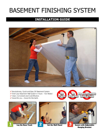
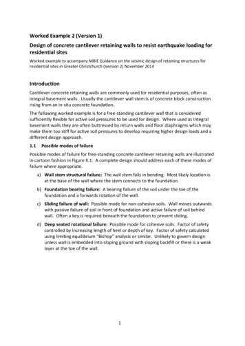
DESIGNINGConcreteBasement WallsMake sure the wall is strong enoughto resist the lateral pressure of the soilConcrete basement walls aredesigned to do two mainjobs. One job is supportingthe house; the other isholding back the pressure of soilagainst the side of the basement.by Brent Anderson, P.E.Considering the nature of concrete,holding up the weight of the house isthe lesser worry. Concrete’s compressive strength is much greater than itneeds to be to support a house. Aslong as the soil under the footing hasadequate bearing capacity, the abilityof a concrete wall to carry the load isnot a question.Soil pressure against the basementwalls, on the other hand, can sometimes be a problem. A sideways forceagainst a basement wall puts one faceof the wall in tension (see Figure 1,next page), and concrete’s tensilestrength is much lower than its compressive strength. Designing a wall toprevent failure in bending requires aproper analysis of the soil loads andan appropriate structural design ofAPRIL JLC 2002
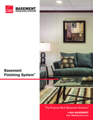
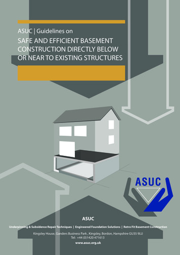
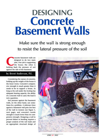
the wall. It’s important to considernot just the wall’s construction, butalso the drainage provided and theway the wall is tied to the house’sfloor frame.In any type of soil, lateral soil pressure increases with depth, so tall wallsget more pressure than short walls.Under identical soil conditions, theload experienced by a 9-foot basementis around 50% greater than the loadfelt by an 8-foot basement. A 10-footbasement feels almost double the loadfelt by an 8-foot basement in the sametype of soil (Figure 2, next page).Taking both conditions together— a taller wall, plus a “heavier” soil —the effects can be severe. For example,a 10-foot basement wall backfilledwith a moderately soft clay soil in anundrained condition feels a load of4,000-plus pounds per foot — close tofour times the approximately 1,250pounds per foot of wall experiencedby an 8-foot basement backfilled withsand or gravel. To handle the load,the taller wall in the heavier soil willrequire a much stouter design.So the ability of a tall basement wallto hold up against soil pressures, especially in poorly drained silt or claysoil, is not something you can takefor granted. It’s important to identifythe soil type on site, to assess thepressure the specific soil will apply toa wall of the height you’re building,and to design the wall accordingly.Many block or treated wood base-Lateral Soil PressureReactionTension zone(dashed line)Soil pressureZone of greatestbending stress(at about mid height)ReactionFigure 1. The amount of pressure applied by the soil varies: It dependson the type of soil, the drainage conditions, and the depth of the backfill. Silt typically applies 50% more pressure than sand or gravel; andclays, when saturated with water, can apply two or three times thepressure of sand or gravel.APRIL JLC 2002ments, and even some concrete basements, have failed when assumed soilpressures typical of sand or gravelwere used for the design but actualsoil conditions involved a poorlydrained silt or clay backfill.Soil Type, Drainage & PressureSoil can be the hardest material inall of construction to define. Even ona single site, soil is seldom uniformin particle size, density, mineralmakeup, or moisture content. And it’svery hard to identify soils by eye: Ashovelful of soil that seems to have alot of sand and gravel in it could wellcontain 30% clay or more. If so, itwould behave like clay, not sand withregard to bearing capacity, drainability, and lateral pressure of soil.Computers have helped us refineour computations about soil mechanics, but analyzing soil loads stillinvolves a lot of uncertainty. The theories and formulas we use are typically just general approximations.Uncertainty about soil loading isone reason engineers usually employsignificant factors of safety in foundation design.But knowledge and understandingof soil can help put lateral earth pressure in proper perspective. Soils canbe identified, and, once identified,their properties can be predicted withreasonable confidence. This providesa basis for safe and economical designdecisions.Also, because dry soil exerts less pressure than wet soil, the lateral pressureof soil can be reduced by providing agood foundation drainage system. Thisenables an experienced designer to usea less conservative factor of safety inthe design of the wall structure, as longas good quality control on site ensuresthat the proper drainage details are reliably put in place.Categorizing soils. In the U.S.,most engineers and constructioncompanies use the Unified SoilClassification System to identify andcategorize soils (see Table 1, page 4,for a condensed version). If you have
lab testing done on a soil sample, thereport will probably use these soiltype classifications.For our purposes, I’ve simplified thepicture by grouping the various soiltypes into five main classes, based onapproximate values for the lateralpressure of soil (Table 2, page 5).(These classes aren’t the same as the“groups” given in Table 1.) If you canbe confident about which class yoursite soils fall into, you can estimatethe lateral pressure of soil on yourwall and build the wall accordingly.Don’t guess, however: Unless youhave reliable data on the soil from asoil engineer’s site report or a laboratory soil test, assume a load conditiontypical of clay, not sand.Soil pressure is given in the form of“equivalent fluid pressure.” This isbased on the understanding that soilpressure, like water pressure, increaseswith depth. Just as water pressure ona submarine deep in the ocean isgreater than water pressure on thatsubmarine at the surface, and just asthe pressure of wet concrete is greatest at the bottom of the forms, soilpressure is found to be greater at thebottom of a basement wall than atthe top. When we estimate the totalload on a wall from lateral soil pressure, we total up the accumulatedpressures at every depth and expressthat as a single number. The greaterthe equivalent fluid pressure of thesoil type, and the greater the backfillheight (wall depth), the greater thistotal load will be.The values I’ve provided for equivalent fluid pressure in each soil classassume that the builder has providedcontinuous exterior footing drainswith a gravel cover. Builders in someparts of the country, however, arestill installing drains on the interiorof footings under the basement floor,instead of outside the footings, eventhough that violates code in mostlocalities. If you use an interior ratherthan an exterior footing drain, thedrainage won’t be as effective, andthe soil may sit in an undrained con-Load Comparison:Soil Type and Wall HeightLoad on an 8'-0" WallBackfilled with Sand or Gravel(30 pcf/ft)Load on an 8'-0" WallBackfilled with Clay(60 pcf/ft)1250 lbs/ft2500 lbs/ftLoad on a 10'-0" WallBackfilled with Sand or Gravel(30 pcf/ft)2065 lbs/ftLoad on a 10'-0" WallBackfilled with Clay(60 pcf/ft)4131 lbs/ftFigure 2. Soil type and backfill height both affect the lateral pressure on a basement wall. Backfilling with a clay soil instead of sand can increase the load bydouble or more, while going from an 8-foot to a 10-foot wall, just a 25% heightincrease, adds 50% to the lateral pressure. Taller walls backfilled with heavier soilrisk failure unless correct design methods are followed.APRIL JLC 2002
Properties of Soils According to theUnified Soil Classification SystemSoil GroupGroup IGroup IIUnified SoilClassificationSystem (Expansion)GWWell-graded gravels, gravel-sandmixtures, little or no finesGoodLowLowGPPoorly graded gravels or gravelsand mixture, little or no finesGoodLowLowSWWell-graded sands, gravelly sands,little or no finesGoodLowLowSPPoorly graded sands orgravelly sands, little or no finesGoodLowLowGMSilty gravels, gravel-sand mixturesGoodMediumLowSMSilty sand, sand-silt mixturesGoodMediumLowGCClayey gravels, gravel-sand-clay mixturesMediumMediumLowSCClayey sands, sand-clay mixturesMediumMediumLowMLInorganic silts and very fine sands,rock flour, silty or clayey fine sands orclayey silts with slight plasticityMediumHighLowCLInorganic clays of low to mediumplasticity, gravelly clays, sandy clays,silty clays, lean claysMediumMediumMedium to LowCHInorganic clays of high plasticity, fat claysPoorMediumHighMHInorganic silts, micaceous or diatomaceousfine sandy or silty soils, elastic siltsPoorHighHighOLOrganic silts and organicsilty clays of low plasticityPoorMediumMediumOHOrganic clays of medium tohigh plasticity, organic siltsUnsatisfactoryMediumHighPtPeat and other highly organic soilsUnsatisfactoryMediumHighGroup IIIGroup IVSoil DescriptionFrostHeavePotentialThe percolation rate for good drainage is over four inches per hour, medium drainage is two to four inches per hour, and poor is less than twoinches per hour.Table 1. The table above shows the two-letter designations for the soil types defined in the Unified Soil Classification System, whichis widely used for construction engineering. A soil engineering report will usually use this scheme to identify soils on a site. In general, sands and gravels have good characteristics for bearing strength and drainage, while soils that contain more fine silt or clayare weaker and drain more slowly. Soils that contain large amounts of decaying plant material (the peats and organic clays) are nogood for building and have to be removed.APRIL JLC 2002
Design Lateral Soil LoadClass IClass IIClass IIIClass IVClass V30 pcf/ft45 pcf/ft60 pcf/ft75 pcf/ft90 pcf/ftGP, GW, SW, SP, GMGC, SK, SC, SM-SCML, CL, ML-CLOLOH, CH, MHTable 2. For purposes of basement wall design, the author has created this simple grouping of soil types from the Unified SoilClassification System. Each class has a typical "equivalent fluid pressure" that is used to estimate the total lateral pressure of soilon a basement wall. The coarse, granular sands and gravels in Class I exert the least pressure, while increasingly finer and moreplastic soils fall into higher and higher classes and are assumed to apply a greater load. The clays and silts with high plasticity(grouped in Class V) apply the greatest lateral pressure; walls in such soils need to be very thick or contain large amounts of reinforcing steel. Effective drainage can help to reduce the in-service load applied by all types of soil.dition and exert higher pressures. Sowithout exterior footing drains, thewall design should use the soil pressure of the next higher class: that is,45 pcf/ft in a sand soil, 60 pcf/ft in asilt soil, and so on. I’ve seen manybasement wall failures in masonryblock foundations equipped withinterior rather than exterior footingdrain systems.Building Strong WallsA concrete wall’s strength dependson the quality of the concrete, thethickness of the wall, and the presence or absence of steel reinforcement. When soil conditions place ahigher load on the wall, you don’tnecessarily have to add steel to thewall; instead, using the plain concretedesign method described on page 7,you can increase a wall’s strength bythickening the wall, using a strongerconcrete mix, or both.For the highest loads, you’re sometimes going to need steel; but up to acertain point, the choice betweenplain concrete and reinforced concrete is a practical one — eitheroption could be more economical,depending on your local costs forSteel Requirements for Walls in Various Soil ConditionsDesigned According to the ACI 318 Ultimate Strength MethodSoil TypeEquivalent Fluid Pressure (f)SandSiltClayWet Silt or ClayFat Clayf 30 pcf/ftf 45 pcf/ftf 60 pcf/ftf 75 pcf/ftf 90 pcf/ftSteel Requirement8-inch wall, 8'0" highwith 7'4" of backfill#4 bar at 48" O.C.#4 bar at 36" O.C.#4 bar at 24" O.C.#4 bar at 24" O.C.#4 bar at 18" O.C.8-inch wall, 9'0" highwith 8'4" of backfill#4 bar at 36" O.C.#4 bar at 24" O.C.#4 bar at 18" O.C.#4 bar at 16" O.C.#4 bar at 12" O.C.8-inch wall, 10'0" highwith 9'4" of backfill#4 bar at 24" O.C.#4 bar at 16" O.C.#4 bar at 12" O.C.or #5 bar at 18" O.C.#5 bar at 16" O.C.#5 bar at 12" O.C.Table 3. The table above shows steel requirements for concrete walls built in soils of various equivalent fluid pressures at variousheights, based on the "ultimate strength" method found in the American Concrete Institute’s ACI 318 Code. The taller the wall andthe greater the soil pressure, the greater the amount of steel that's called for. This chart assumes an 8-inch wall thickness. In allcases, a 3,000-psi concrete mix should be used.APRIL JLC 2002
Examples of Plain Concrete Basement WallsBackfilled With Various Soil TypesTable 4a(Assumes continuous exterior footing drain tile with gravel cover and approved wall-to-sill connection)Soil TypeEquivalent Fluid Pressure (f)SandSiltClayWet Silt or ClayFat Clayf 30 pcf/ftf 45 pcf/ftf 60 pcf/ftf 75 pcf/ftf 90 pcf/ftMinimum Wall Thickness (2500 psi concrete)(Wall 8'0" high with 7'4" of backfill)8 inches10 inches10 inches12 inches12 inches(Wall 9'0" high with 8'4" of backfill)10 inches12 inches12 inchesengineering requiredengineering required(Wall 10'0" high with 9'4" of backfill)10 inches12 inchesengineering requiredengineering requiredengineering requiredMinimum Wall Thickness (3500 psi concrete)(Wall 8'0" high with 7'4" of backfill)8 inches8 inches10 inches10 inches12 inches(Wall 9'0" high with 8'4" of backfill)8 inches10 inches12 inches12 inchesengineering required(Wall 10'0" high with 9'4" of backfill)10 inches12 inchesengineering requiredengineering requiredengineering requiredMinimum Wall Thickness (4500 psi concrete)(Wall 8'0" high with 7'4" of backfill)6 inches8 inches10 inches10 inchesengineering required(Wall 9'0" high with 8'4" of backfill)8 inches10 inches12 inches12 inchesengineering required(Wall 10'0" high with 9'4" of backfill)10 inches12 inchesengineering requiredengineering requiredengineering requiredTable 4b(Assumes continuous exterior footing drain tile with gravel cover, approved wall-to-sill connection, and dimpled-sheet drainage membraneattached to foundation wall for enhanced soil drainage)Soil TypeEquivalent Fluid Pressure (f)SandSiltClayWet Silt or ClayFat Clayf 30 pcf/ftf 45 pcf/ftf 60 pcf/ftf 75 pcf/ftf 90 pcf/ft8 inches10 inches10 inches10 inchesMinimum Wall Thickness (2500 psi concrete)(Wall 8'0" high with 7'4" of backfill)6 inches(Wall 9'0" high with 8'4" of backfill)8 inches10 inches10 inches12 inchesengineering required(Wall 10'0" high with 9'4" of backfill)10 inches12 inches12 inchesengineering requiredengineering required6 inches8 inches8 inches10 inches10 inchesMinimum Wall Thickness (3500 psi concrete)(Wall 8'0" high with 7'4" of backfill)(Wall 9'0" high with 8'4" of backfill)8 inches8 inches10 inches12 inches12 inches(Wall 10'0" high with 9'4" of backfill)8 inches10 inches12 inchesengineering requiredengineering required6 inches8 inches8 inches10 inches10 inchesMinimum Wall Thickness (4500 psi concrete)(Wall 8'0" high with 7'4" of backfill)(Wall 9'0" high with 8'4" of backfill)8 inches8 inches10 inches10 inches12 inches(Wall 10'0" high with 9'4" of backfill)8 inches10 inches12 inches12 inchesengineering requiredTable 4. The tables above show the results of applying the plain concrete design method from ACI 318-99 for a variety of wall heightsand soil conditions. Using a backfill material with a higher equivalent fluid pressure, or increasing the wall height and backfill depth,increases the load on the wall. Increasing the strength of the concrete mix or the thickness of the wall increases the wall’s capacity.So taller walls in heavier soils should be made thicker or with stronger concrete. Table 4a is based directly on the ACI method, but forTable 4b, the author has applied a reduced "strength reduction factor," a factor of safety. The author considers this reduced factor ofsafety to be appropriate for residential work if a dimpled-sheet drainage membrane is applied to the foundation wall to ensure adrained condition in the backfill soil. Table 4b is provided for illustration only; an engineer should be consulted for specific projects.APRIL JLC 2002
concrete, steel, and labor. Butwhether you choose to spend yourbudget on concrete (pouring a thickerwall) or on steel and labor time (having the crew place and tie rebar), it’simportant to match the solution torealistic load assumptions.The ACI 318 Code. Concrete structural design rules are found inBuilding Code Requirements forStructural Concrete (ACI 318), anAmerican Concrete Institute document that is revised periodically toreflect advances in technology andunderstanding.Ultimate strength method. Table 3for steel-reinforced walls (page 5) isdrawn directly from the “ultimatestrength” method long established inACI 318. The taller the wall and thegreater the assumed soil pressure, themore steel that’s needed. The on-center dimensions given here are forboth vertical and horizontal steel. Forthis table, I have assumed a concretecompressive strength of at least 3,000psi (28-day value), but the concretestrength is less of a structural issuewhen steel reinforcement providesthe necessary tensile strength on thetension face of the wall.Plain concrete method. The latestversion of the 318 Code, ACI 318-99,contains a new Chapter 22, whichexplains the “plain concrete” methodused to design unreinforced walls.Under that method, the greater theassumed soil pressure or the taller thewall, the thicker the wall must be.Increasing the compressive strength ofthe concrete also improves the wall’scapacity to handle lateral soil pressures, because concrete’s tensilestrength, while low, increases whenthe compressive strength is increased.In Tables 4a and 4b (previous page), Ihave applied the Chapter 22 methodto arrive at required wall thicknessesfor walls of 8-foot, 9-foot, and 10-footheights in a range of soil classes. I’veincluded only three compressivestrengths (2,500 psi, 3,500 psi, and4,500 psi), but it’s possible to getgreater wall strengths by usingstronger mixes, thus perhaps allowinguse of a thinner wall.Walls designed with the plain concrete method are unreinforced walls;the only rebar I generally call for inthose walls is two horizontal #4 (halfinch) bars near the top and one horizontal #4 bar near the bottom for crackcontrol. (It can also be helpful to placerebar near window and door openingsand behind beam pockets, but that’s asubject for another article.)Table 4a is derived from applying theChapter 22 methods by the book. Table4b is based on my own experience andknowledge in wall design and construction, and represents what I consider an appropriate modification ofthe factor-of-safety to reflect the effectof careful attention to drainage andbeen used before may have been filledin with unsuitable material. Any timeyou’re not sure of the soil type, getting a soil boring or an engineer’s sitereport is good insurance.Most structural wall failures occurduring construction, because of careless backfilling without proper wallbracing. In service, most wall failureshappen because of the gradual consolidation of saturated fine soil, resultingin excessive soil loading after manyyears of increasing pressure.Fine soils in particular exert lowerpressures when in a drained condition. So good surface drainage andproper footing drains around theentire perimeter are the most important features for watertight and structurally sound basement walls.Most in-service wall failures happen because ofthe gradual consolidation of saturated fine soilbracing details. As you can see, undersome soil conditions, Table 4b wouldallow a thinner wall than Table 4a.In my opinion, Chapter 22 shouldbe revised again to allow for a lessconservative wall structure whendrainage and bracing are properlyaddressed, as in Table 4b. I believethat historical experience with actualwalls in service indicates that thiswould be an appropriate change. Butit has yet to be made, so bear in mindthat Table 4b is only one engineer’sopinion. You should apply a similarapproach on your own jobs only withthe advice and approval of thedesigner or engineer responsible for aparticular job.Soil Pressure Loads in PerspectiveAs building development continues, the “good” building sites arebeing used up. More and more, wehave to put houses on marginal land.Low-lying property near water islikely to have soft, poorly drainingsoil, and urban properties that haveAPRIL JLC 2002Dimpled-sheet drainage membranesprovide the best drainage and willallow most soil types to be used safelyfor backfill, because the soil can bekept in the drained condition.Bracing the foundation wallsagainst backfilling loads is the secondmost important factor. It’s best to tiethe floor frame to the foundationbefore backfilling; otherwise, a solidwall brace every 15 feet or so is recommended.Wall design has to match the wallstructure to the lateral loads of soil.But if the bracing and drainage procedures I’ve described are followed, thesoil loading creates less of a risk. Thewall design can take that reduced riskinto account. The result will be a wallthat performs well in service, at amore affordable cost.Brent Anderson is a professional engineer and concrete consultant. HisMinneapolis-area company provides concrete construction, investigation, andrepair services.
For example, a 10-foot basement wall backfilled with a moderately soft clay soil in an undrained condition feels a load of 4,000-plus pounds per foot — close to four times the approximately 1,250 pounds per foot of wall experienced by an 8-foot basement backfilled with sand or gravel. To handle the load, the taller wall in the heavier soil will