Transcription
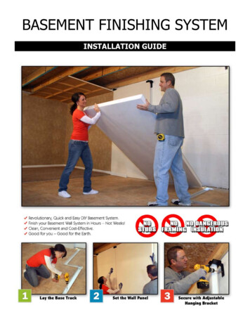
BASEMENT FINISHING SYSTEMINSTALLATION GUIDE
Two Person AssemblyBASEMENT FINISHING SYSTEMINSTALLATION GUIDEB.2-Pc. AdjustableHanging BracketE.CORNERBRACEF.“C” CHANNELA.BASEMENTFINISHING PANELD.BASE TRIMC.BASE CHANNELTOP VIEWPanel - to - PanelConnection“C” ChannelDescriptionAssemblyLetterBasement Finishing PanelA2-Pc. Adjustable Hanging BracketBBase ChannelCBase TrimDCorner BraceE“C” ChannelFElectricalRacewaySplines(for door or opening)Required ToolsPencilSafety GlassesGlovesPutty KnifeChalkBoxTapeMeasureMitreSawPhillips BitMasonaryDrill BitDrillJig SawSawHorsesKnifeLevel2Circular SawStepLadderSquare TEMO INC. 2011
TABLE OF CONTENTS1.0PLANNING AND PREPARATION42.0BASE CHANNEL - LAYOUT62.1BASE CHANNEL - CUTTING72.2BASE CHANNEL - INSTALLATION83.0BASEMENT PANEL HEIGHT93.1ADJUSTABLE HANGING BRACKET103.2SETTING INITIAL ADJUSTABLE HANGING BRACKET123.3SETTING INITIAL BASEMENT PANEL133.4SETTING STANDARD WALL CAP144.0SETTING BASEMENT PANELS155.0TURNING THE CORNER - INSIDE CORNERS166.0TURNING THE CORNER - OUTSIDE CORNERS177.0CUTTING AROUND OBSTACLES188.0DOOR OPENINGS199.0WINDOW OPENINGS2110.0BASE MOLDING2211.0FINISHING THE SPACE2312.0INSTALLERS HELPFUL HINTS243 TEMO INC. 2011
1.0 PLANNING AND PREPARATIONDue care should be taken to insure that the project and work area’s are clean, dry and hazard free prior tocommencement.Check to ensure the integrity of the exterior foundatoin walls and that all cracks and/or problems have been properlyrepaired.Always adhere to proper safety construction practices and procedures including but not limited to the use of safetyglasses during all phases of the Basement Finishing System installation.Always obtain professional help from certified individuals within specialized trades that are required by code and/or inareas/tasks that you are not comfortable and confident in achieving on your own.Check and abide by all applicable code requirements for finished basement fire stop systems.Provide and install proper fire stop systems within the proposed project area prior to the start of the BasementFinishing System.It is recommended that all panel cuts be done in a separate large open air environment for ease of material andpersonal movement and proper cutting practices, as well as the added benefit of maintaining a clean installation area.With the aid of the TEMO, Inc. Basement Finishing System layout and design sheet, create your own custombasement configuration.The grid pattern of the graph area is set up in a 1/4” 4’-0” proportion. This pattern allows for easy configurationand calculation of lengths of materials needed to complete your design.Each basement panel comes in a standard 4’- 0”x 8’- 0” dimension but can be cut down in length, width and notchedout to conform to/or around existing basement conditions to achieve final basement design.All basement panels are designed to be installed vertically with the tapered edges of the 4’ -0” wide panels abuttingthe tapered edge of the adjacent vertically installed wall panel.While designing your basement be conscience of the proposed location of walls in regards to any impending obstaclesthat may hang down from above.Use the helpful material list to pick up all the essential TEMO Basement Finishing System products to complete yourdesign.After completion of pre construction check list and finalization of your custom basement design you are ready to startthe Basement Finishing System installation. TEMO INC. 20114
1.0PLANNING AND PREPARATIONDRAW YOUR DESIGN BELOWONCE YOUR DESIGN ISCOMPLETE FILL IN THEINFORMATION BELOWTotal Length of Design (ft.)# of Doors# of Inside Corners# of Partition Openings# of Outside CornersAssemblyLetterSizeBasement Finishing PanelsA4’ x 8’2-Pc. Adjustable Hanging BracketBBase ChannelC8’Description1 SQUARE 4 FEETFormulaMaterial ListTotal Length of Design / 4(Total # of Basement Finishing Panels) (# of Corners)Total Length of Design / 8Base TrimD8’Total Length of Design / 8Corner BraceE8’Total # of Inside Corners / 4“C” ChannelF8’Total # of Doors * 35 TEMO INC. 2011
2.0 BASE CHANNEL - LAYOUTBegin base channel installation by measuring and marking the floor 1½” away from the interior face of the perimeterfoundation wall. Be sure to mark the floor in several places along the length of the wall especially measuring off anycrown or high points in the wall plain.Using a chalk box snap a straight line across the floor using the 1½” offset floor mark that is furthest away from thewall and closest to the wall on the opposite side of the room. This will ensure that the minimum base channel offsetwill be achieved for the entire length of the wall.Next measure and snap chalk lines for the remaining base channels in the design. Remember to maintain yourminimum distance form any perimeter foundation wall.Check for and strive towards proper 90 square inside and outside corners to ensure optimal product installation andfinish.Properly measure mark and carefully cut base channel using hand or power saws equipped with approved metalcutting blades. Use metal files to knock down and smooth off any extraneous metal burs to ensure proper fit andalignment with the adjacent base channel.6 TEMO INC. 2011
2.1 BASE CHANNEL - CUTTINGInside corners can be laid out in either a mitered corner connection or a flush abutting configuration.All outside corner must be laid out in a mitered configuration to accept proper basement panel installation to becovered later in these instructions.See Figs. 2.12- 2.14 on this page for further graphic representations of approved corner configurations.Place the edge of the properly measured and cut (if necessary) base channel along the snapped caulk line on thefloor.Please note that the length of your base channel will vary depending on the configuration of your corners. Adeduction or addition of the base channel width may be need to accomodate your design (Fig. 2.13).Fig. 2.12Inside CornerFig. 2.13Outside CornerFig. 2.14Inside Corner Alternate Configurations7 TEMO INC. 2011
2.2BASE CHANNEL - INSTALLATIONESCREW LINEWALL PANELLEDGE Next identity the screw line located in the center of the base channel running its entire length.Using a power drill, drill pilot holes through base channel and into the basement floor, along the screw line.Start your initial pilot hole (Fig 2.22) 6” from the outside edge of your first base channel.The additional base channel screw attachment pattern should fall 3’-6” on center, starting from the initial pilot holeand running the remaining length of the base channel for that wall.For typical basement concrete floor attachment use ¼” diameter by 1½” long masonry anchors in every pilot holeincluding the initial hole 6” from the beginning edge of the base channel.For walls less that 4’-0” in length provide a minimum of two base channel attachment anchors no less than 6” fromthe outside edges of the base channel.Repeat the attachment process to each base channel working your way around the design.Fig. 2.21 Base Channel Attachment Placement8 TEMO INC. 2011
3.0 BASEMENT PANEL HEIGHTExisting structuralframing or fire stopAfter base channel installation is complete,you are ready to start determining basementpanels and Adjustable Hanging Brackets.There is no absolute starting point forbasement panel installation. All finishedbasement layouts provide unique situationsand pre-planning should be consideredwhen choosing proper starting and endpoint(s). All basement panels should be individuallymeasured and cut if necessary as installationprogresses. Proper basement panel measurements canbe achieved by measuring the distance fromthe base channel panel ledge vertically tothe under side of the existing structuralframing or fire stop system. Subtract 1” fromyour total height measurement for properbasement panel installation clearance toarrive at your overall basement panel height(see Fig. 3.01). Lay individual basement panels flat(horizontally) across a set of saw horses(see Fig. 3.02). Measure and mark youroverall wall panel height and scribe aline across the entire face of basementpanel. Using a powered circular saw with astandard carbide blade cut each panel downto its necessary height. Due to possible pitch in finished basementfloors, it may be necessary to shim thebase of individual basement panels, withapproved, non-biodegradable shims. Shims will provide the necessary angle toallow two (2) adjacent basement panelsedges to abut one another, encompassingtwo (2) basement panel connection splines,forming a closed panel connection withoutany gaps. (See Fig. 3.03)1” DeductionFoundationwallOverall panelheightLedge of base channelFig. 3.01 Establishing overall panel heightFig. 3.02 Using saw horses to cut panelsFig. 3.03 (Right) Proper connection of basementpanels. (Left) Shown with gap betweeenbasement panels, a shim will be needed to alignpanels properly.9 TEMO INC. 2011
3.1ADJUSTABLE HANGING BRACKETD Prior to setting the first basement panel you will need to install the initial Adjustable Hanging Bracket. The AdjustableHanging Bracket is comprised of two (2) major components and the necessary hardware for joining them in their finalconfiguration. The first component is an “L” bracket comprised of one slotted leg and one plain leg. The leg with theslotted adjustable mounting area attaches to the existing foundation wall or overhead structure. The plain leg slidesinto and attaches to the second major Adjustable Hanging Bracket component, the wall cap. While the wall cap’s tongue is used to connect to the L bracket the wall cap’s downward legs are attached to theface of a basement panels. Adjacent basement panels that combine to make up a single wall run will share a singleAdjustable Hanging Bracket connected to both panels (See Fig. 3.11).10 TEMO INC. 2011
3.1ADJUSTABLE HANGING BRACKETThere are three (3) typical Adjustable Hanging Bracket configurations to assist you in achieving your Temo FinishedBasement layout goals. Choose the proper Adjustable Hanging Bracket configuration for each wall run maintaining allrequired air spaces while providing greatest structural integrity. Adjustable Hanging Bracket configuration “A”is a standard perimeter wall configuration usedwhenever your proposed wall runs in proximityor parallel to the existing foundation wall.(See Fig. 3.12). Adjustable Hanging Bracket configuration “B”is used when your interior partition wall runsperpendicular to the existing floor joist. (SeeFig. 3.13). Adjustable Hanging Bracket configuration “C”is used when your interior partition wall runsin proximity or parallel to existing floor joists.(See Fig. 3.14).11 TEMO INC. 2011
3.2SETTING INITIAL ADJUSTABLE HANGING BRACKET1’-0” from the edge of the panel1/2” from the topedge of the panelXPanelheightTop of basechannel ledgeFig. 3.21 Measure to determine basement panel height For instructional purposes, installation procedures will be given for a standard perimeter wall Adjustable HangingBracket configuration “A” (See Fig. 3.12) working in a left to right directional pattern. To set initial (not typical bracket installation) Adjustable Hanging Bracket, determine the left edge of first basementpanel, measure 1’-0” to the right and mark your base track. Using a framing level, strike a vertical line to theunderside of the existing framing (see Fig. 3.21). Assemble the L Bracket and wall cap without attaching them at this point. Place the L Bracket leg against the foundation wall, centering the slotted vertical opening on the line previouslydrawn. Raise the Adjustable Hanging Bracket so that the inside horizontal leg of the cap is at your overall basementpanel height determined in step 3.0. Using a power drill, and appropriate drill bit, pre-drill two (2) pilotholes for masonry wall anchors within the slotted mounting area. Do NOT install attachment hardware at the very top and bottom ofslotted mounting area. Leave room above and below wall anchors to allow for minoradjustments to the Adjustable Hanging Bracket final height. Place Lbracket against the wall and install two (2) ¼” x 1 ½” long masonryanchors through the slotted mounting track. (See Fig. 3.22).Fig. 3.22 Anchoring theAdjustable Hanging Bracket12 TEMO INC. 2011
3.3SETTING INITIAL BASEMENT PANELFig. 3.31Standing basement panel into placeFig. 3.32Initial location of panel and bracket Once basement panel has been cut to proper height, begin installing basement panel by placing it into the basechannel on an angle, and straighten panel into upright vertical position (See Fig. 3.31) Slide basement panelhorizontally over and through downward legs of Adjustable Hanging Bracket wall cap till reaching its proper startinglocation (See Fig. 3.32). With the inside horizontal leg of wall cap flush to basement panel’s top edge, attach wall cap downturn leg tobasement panel using a power drill and two (2) #6 drywall screws (see Fig. 3.33) Using a framing level, make sure wall panel within base channel is level, attach wall cap to L bracket with two (2)screws (provided in the Adjustable Hanging Bracket) through the predrilled holes in the wall cap attachment tongue.(see Fig. 3.34)Fig. 3.33 Attach WallCap to Wall PanelFig. 3.34 Attach Wall Cap to L Bracket13 TEMO INC. 2011
3.4SETTING STANDARD WALL CAPFig. 3.42Pre-drill pilot holesFig. 3.43Secure to foundation wallFig. 3.41Trace slot in mounting bracket onto foundation wall. Standard wall caps are found anywhere the verticaledges of two (2) adjacent basement panels meet (SeeFig. 3.11). After setting initial Adjustable Hanging Bracket onleft side of panel, and initial basement panel, dry fitanother Adjustable Hanging Bracket together andplace atop right side of basement panel. AdjustableHanging Bracket should be slightly off centered to theright of previously installed basement panel for ease ofpilot hole drilling and anchor attachment installation.Trace slotted mounting track opening onto foundationwall (See Fig 3.41). Remove Adjustable HangingBracket and attach L bracket to foundation wall (asper described in 3.2) by pre drilling pilot holes (SeeFig. 3.42) and securing with masonry anchors (SeeFig. 3.43). Slide wall cap onto L bracket plain leg andattach ONLY the left side of wall cap downturn leg tobasement panel. Install two (2) basement panel splines in the pregrooved slots located on the sides of each paneldirectly behind exterior face of basement panel (SeeFig. 3.44). Note: splines may need to be cut down tomatch overall height determined for basement panel.14Fig. 3.44 Insert Splines TEMO INC. 2011
4.0SETTING BASEMENT PANELSFig. 4.01 Insert SplinesIn the right side of initial basement panel insert two (2) panel splines (cut to proper size as necessary) into panel splinegrooves (See Fig. 4.01). Next install second (proper height) basement panel on angle into base channel, straightenpanel into upright vertical position, (See Fig. 4.02) slide panel horizontally over and through downward legs of wall cap,inserting exposed edges of panel splines into receiving grooves ( See Fig. 4.03). Push wall panels together until adjacentedges of wall panels abut each other without gap. Using a power drill secure right side of wall cap downturn leg to faceof second basement panel using one (1) #6 drywall screws (See Fig 4.04). Using a framing level, make sure basementpanels are level, and finish securing wall cap attachment tongue to L bracket using two (2) screws (provided in theAdjustable Hanging Bracket) through the predrilled holes in the wall cap attachment tongue. Then repeat the process toremainder of basement panels in the remainder of the wall run.Fig. 4.02 Stand panel inbase channelFig. 4.03 Slide panel intoplace15Fig. 4.04 Attach bracketto panel TEMO INC. 2011
5.0TURNING THE CORNER - INSIDE CORNERSFig. 5.01 Scribe line forcorner brace attachmentFig. 5.02 Attach corner brace Dry fit the two (2) basement panels involved in an inside cornerconfiguration into place and confirm their vertical levels. Scribe a linedown face of basement panel that will receive the corner braces (SeeFig. 5.01). Slide scribed basement panel back out of place enough toattach corner braces. Each inside corner requires a minimum of two(2) 1’-0” long corner braces, attached to a basement panel exteriorskin using a minimum of two (2) #6 drywall screws. Locate andattach corner braces 1’-0” in from the top and bottom edges and ¼”in from the vertically scribed line closer to vertical edge of basementpanel (See Fig. 5.02). Reinsert basement panel with attached corner braces into basechannel and slide into place making sure the unattached leg of thecorner brace now sits behind the exterior panel skin of adjoiningbasement panel (See Fig. 5.03). Secure basement panels in placewith an Adjustable Hanging Bracket on each panel.Notes:Each turn (inside or outside) of a basement panel system constitutesthe start of a new wall run. Each new wall run begins with theinstallation of an initial Adjustable Hanging Bracket (see 3.2 fordetails) accompanied by an Adjustable Hanging Bracket straddlingeach basement panel to basement panel connection.All initial basement panels within a single wall run, greater than 2’0” in length require the installations of two (2) Adjustable HangingBrackets.16Fig. 5.03 Insert panel and attach TEMO INC. 2011
6.0TURNING THE CORNER - OUTSIDE CORNERSFig. 6.01 Setting proper depth3 3/8”Fig. 6.02 Measure thickness ofpanel to removeFig. 6.03 Make sure panelsfit together and level Outside corners connections require the notch out of one panel tobecome the cap to its perpendicular counterpart. Lay basement panelhorizontally across two (2) saw horses desired finish face down. Usinga powered circular saw set the depth of the adjustable foot plate toremove one finished wall panel skin and entire deep of interior foampanel core (See Fig. 6.01). Measure 3 3/8” in from the edge of panel to be cut off, and scribea line the length of the panel. With properly adjusted circular sawremove backside portion of basement panel (See Fig. 6.02). Notefor straighter cuts use a circular saw equipped with an adjustable ripfence feature. Using a putty knif remove any remaining or stray interior foam panel core from the backside of proposed finishedexterior panel skin, thus insuring a proper unimpeaded corner assembly. Install basement panel in base channel and tilt to upright vertical position. Check vertical level of both panels andcompletion of proper corner connection (See Fig. 6.03). Secure basement panels in place with an Adjustable HangingBracket on each panel (See Fig. 6.04). Note: Dependent on final layout one or both wall panels involved in cornerconnects may need to be cut to specific sizes.17Fig. 6.04 Secure panel withAdjustable Hanging Bracket TEMO INC. 2011
7.0CUTTING AROUND OBSTACLESFig. 7.02 Lift and slide in pre-cut panel around obstacle Carefully measure horizontal and vertical distances toexisting impeding obstacle preventing the installationof the next full height basement panel. Using a powercircular saw, reciprocating, or jig saw (depending onsize of cut out required) remove necessary panel area orsurface for proper panel installation. Due to the processof panel installation it will be necessary for the additionalsubtraction of at least 1” to actual obstacle dimensions(see Fig. 7.01). This additional cut away panel clearanceallows basement panels to rise above and slide down intothe base channel as well as misses previously installedpanel splines. Tilt basement panel towards away from foundation wall,place panel inside base channel making sure impedingoverhead obstacle fall within cut out panel area. Tiltbasement panel up into an upright vertical position,(See Fig. 7.02) then slide panel onto panel splines andfirmly against adjacent basement panel (See Fig. 7.03)Continue with normal basement panel installation withthe addition of the next Adjustable Hanging Bracket.Note: if basement panel cut out area occurs through areaof panel union, provide Adjustable Hanging Bracket asclose as possible to proper location as situation permits.18Fig. 7.01 Properly measure obstalce toinsure precise cutting of panel TEMO INC. 2011
8.0DOOR OPENINGSFig. 8.01 Install C Channel into basement panel Openings through TEMO’s Finish Basement System require preparation and finishing of exposed basement paneledges. For creating wall openings, first install full height basement panels on either side of proposed wall opening area. Install C Channel jamb legs vertically along full height of basement panels. (See Fig. 8.01) To install C Channel simply slide channel between basement panel exterior skin and foam wall core. When usingthe factory edge of wall panel the C channel simply slides in place where panel splines usually sit. For factory edgeswithout provided panel spline grooves or customer cut panel edges, simply create a groove for the C Channel to sitinto between the back sides of the panel’s exterior skins. This groove can be accomplished with the aid of a circularsaw or simple sharp putty knife. Take caution to create a clean smooth groove to insure a flush tight final fit betweenbasement panel and C Channel (See Fig. 8.02).Using #6 drywall screws at 1’-4” on center attach the edge of thebasement panel to the vertical wall opening C Channel jamb legs.Fig. 8.02Use either a circular sawor a putty knife to open upa groove to accept the CChannel.19 TEMO INC. 2011
8.0DOOR OPENINGS Next create a header panel by measuring offyour established wall opening height to the topof your over all basement panel height, and cuta basement panel down to proper dimensions forwall opening. Measure, cut and install C Channelto the full length of the bottom side of headerpanel. Measure and cut C Channel for the verticallegs of the header panel. Notice legs do not runfull length of header panel because of previouslyinstalled bottom C Channel piece (See Fig. 8.03). Align vertical header panel legs to vertical wallopening jamb legs starting at top of basementpanel. Using a minimum of two (2) # 8 specifiedsheet metal screws, symmetrical spaced apart,attach header panel legs to vertical wall openingjamb legs (See Fig. 8.04). Fig. 8.03 Create headerPlace header panel within wall opening and slideupwards, encompassing C Channel header legstill reaching desired wall opening height (See Fig.8.05). Secure all C Channels to basement panelsusing specified #6 drywall screws at 1’-4” oncenter.Fig. 8.04 Attach header panel legs Once header panel is in final location, cut andinstall two (2) 3 ½” long corner brace segmentsto the intersection of the header panel base andthe vertical wall opening C Channel legs. Securecorner Braces to C Channel legs using a minimumof two (2) #8 sheet metal Screws, spacedsymmetrically, per leg of corner brace (See Fig8.06) Finish wall opening to desired look usingbasement panel skins (See 10.0 for details) or apre hung door assembly.Note:If finishing off wall opening with premanufactured pre hung door, see required doorrough opening requirements per manufactureprior to installing base track or framing to dooropeningFig. 8.05 Slide in and secure headerFig. 8.03 Attach corner braces20 TEMO INC. 2011
9.0WINDOW OPENINGSFig. 9.01 Finishing out an exterior window Windows openings weather found within a wall run or at the top of a wall (See Fig 9.01) are a form of obstacle towork basement panels around. Therefore refer back to section 7.0 for necessary steps for cutting out around obstacles. Note unless part of the window assembly projects into the finished basement area (not shown in fig. 9.01) thereis no need for additional horizontal or vertical distances to be added to basement panel cut out dimensions. Projectsquare, level lines off existing window opening and cut basement panel to achieve projected measurements. After basement panel has been cut out to proper size provide the addition of door C channel to all vertical and horizontal exposed basement panel foam surfaces as described in 8.0 door openings. Carefully measure and cut out sizes and shapes to window well opening to be sheathed in finished basement panelskin. Hint: Cut and install vertical legs first, install horizontal base second to help keep legs in place. Attach basement panel skins to existing masonry foundation walls and to C channel using water based adhesive andtwo (2) #6 drywall screws per skin. See Fig. 9.02 for example of completed window well enclosure.Note:Do NOT install any finished assembly that interferes or hinders any window’s operational capabilities21 TEMO INC. 2011
10.0 BASE MOLDINGFig. 10.01 Base TrimFig. 10.02 Base Trim Assembly TEMO, Inc. patented base molding system combines the ease of installation with the comfort of no maintenance andthe beauty of traditional profile. As with basement panel installation, there is no absolute starting point for base molding installation. Careful preplanning or a dry layout fit can help determine the best starting point or locations for base molding seams. Inside andoutside corners require angle cuts to create mitered joints, while in wall molding seams may be simply installed byabutting one base molding piece to the next till you reach the end of the wall run. Noting required end connectionsto adjacent base molding pieces, and or vertical casement legs, measure length of necessary base molding and cutaccordingly. On the back side of the base molding is a downward turned leg. Carefully place base molding downward leg againstface of basement panel and slide down between panel face and upward turn leg of base channel. Push down untilbase molding touches the floor. (See Fig. 10.02) Base molding installation leg provides the opportunity to adjust to multiple heights depending on type of final finishfloor system installed. Base molding is also removable and reusable if flooring system is removed and replacedwithout the worry of damage done to the base molding.22 TEMO INC. 2011
11.0 FINISHING THE SPACEElectrical:All electrical work to be done by proper individualsspecified per applicable building code(s), verify withlocal municipalities. All electrical work to be completed incompliance to latest applicable national, state, and localbuilding codes.Each basement panel comes standard with 1 5/8”diameter electrical wire raceway tubes located 1’-4” infrom either edge of panel and 1’-4” on center from eachother. For easiest electrical box installation locate center ofelectrical raceway on top edge of basement panel, transferthat line down the face of the panel to its desired height.Center and trace the outline of a new remolder versionelectrical box on basement panel face. Using a power drilland ¾” paddle bit bore one hole with in each corner oftraced outline. Connect bored holes with powered jig sawand chip foam panel core away. Bore, plunge cut, andremove panel foam as required to install electrical boxflush with panel finished skin plain. Do NOT cut all the waythrough Basement Panel. Install and secure electrical boxto basement panel following products specifications, verifywith each manufacture for details. Snake electrical wiredown through electrical raceway and into each individualbox.Seam Finish:Standard basement panel seams should be finished usingproper drywall joint finishing procedures. All standarddrywall tools and materials will be necessary for thisstage of the project, including but not limited to drywallmud, paper tape, corner bead, adhesive, drywall knives,sanding sponges or blocks, ect. Finish each seam betweenbasement panels and sand to smooth seamless finish.Painting:Once wall seams are finished basement panels are readyfor primer and paint. Following all standard paintingprocedures prime and paint the walls to your desiredfinish. Temo base molding comes standard in a prefinished white application. Do not paint base molding.Electrical Raceway16”16”16”Each basement panel comes standard with 1 5/8” diameterelectrical wire raceway tubes located 1’-4” in from either edge ofpanel and 1’-4” on center from each other.Measue to find internal racewayTrace the electrical boxCut away skin and foamSnake wire down raceway from the top of the panel until it comes out of thehole you just cut into the panel.Finished Flooring System:With the adjustability of the Temo Inc. base molding thepossibilities of your finished floor system are virtuallyendless. Install flooring system per manufacturesspecifications, then set base molding into base channeland slide down till resting on finished floor.Finished Ceiling:Basement ceilings can be finished in a variety of differentways, two common ways are drywall and drop ceilingsystems, the second being the most popular. Temobasement panels can provide the necessary supportfor drywall ceiling perimeter ledge boards, or dropceiling perimeter L angles. Follow all product hangingrequirements per manufactures specifications.23 TEMO INC. 2011
12.0 INSTALLERS HELPFUL HINTS The following are helpful suggestions to aid in the ease of Temo Finish Basement System. For all Adjustable Hanging Bracket to existing structure connections use ¼” diameter by1 ½” long masonry anchors. For all Adjustable Hanging Bracket to basement panel, basement panel to C Channel, and corner brace to basementpanel connections use a #6 1 ¼” Philips bugle head coarse thread sharp point drywall screw. For all C Channel to C Channel, and corner brace to C Channel connections use a #8 ½” Philips pan head stainlesssteel sheet metal screw. A miter saw equipped with an 80 toothed soft metal carbide blade is recommended for all base channel and basemolding cuts. A powered circular saw equipped with carbide blade is recommended for all basement panel cuts Cut basement panel height subtractions outside or in a separate area. Small notch out cuts can be done in basement using a reciprocating and /or jig saw depending on the size of cutrequired. Do not shim and level out base channel along sloped basement floors. The f
Each basement panel comes in a standard 4'- 0"x 8'- 0" dimension but can be cut down in length, width and notched out to conform to/or around existing basement conditions to achieve final basement design. All basement panels are designed to be installed vertically with the tapered edges of the 4' -0" wide panels abutting