Transcription
HOLLEY SUPERCHARGERINSTALLATION INSTRUCTIONS AND TECHNICAL MANUALCAUTION: All superchargers and turbochargers increase the combustion pressure and temperature within an engine.This puts additional loads on pistons, rings, bearings, crank, rods, and cylinder walls. All of thesecomponents are capable of withstanding substantial increases in combustion pressure under properconditions.In order to avoid potentially severe engine damage, it is critical that the timing and fuel mixture are correct. Detonation (sparkknock) caused by excessive ignition timing, or too high of a compression ratio and/or a lean condition in the carburetor candestroy pistons, rings, and bearings in a short period of time. These conditions coupled with high engine rpm can literallydestroy an engine. Engine speeds in excess of 6,000 rpm are totally unnecessary with a blower, and can be extremelydetrimental. A roots supercharged engine will make maximum torque at a relatively low engine speed.The Holley Powercharger is intended for use on engines with compression ratios of up to 9.50:1 with a maximum blowerpressure of 5-6 psi. Higher boost pressures will require lower compression ratios or a boost retard.The Powercharger is available in three different blower sizes, 144 cu.in./revolution, 174 cu.in./revolution and 250cu.in./revolution. The 144 and 174 blowers are used in low profile applications and the 250 blower is a taller higher performanceblower.See the operation section of these instructions for details of distributor timing and carburetor modifications.These instructions are general installation instructions for all versions of the Holley Powercharger. At the end of theseinstallation instructions there is a technical manual which outlines how the blower works and how you can get the most out of theHolley supercharger.The supercharger is complete in this kit. The pulleys are sold separately. For Powerchargers a different size driven pulley (theupper pulley) is required for different displacement engines, so the correct pulley must be purchased separately. See yourHolley supercharger dealer for applications and part numbers.The automotive versions of the 250 Powercharger include the 2-4 barrel carburetor adapter (#93151). The single 4 barreladapter is also available (#93150).The supercharger, when installed correctly, will not cause any damage to an engine in good operating condition, as long asengine knock, or ping, is controlled. The supercharger should not be used on any engine that is not in good operating condition,or that does not have adequate oil pressure.Before you begin installation of your new supercharger there are some additional Holley products you may wish to consider:Boost Gauge, Part no. 90520: This extremely high quality gauge tells you engine vacuum or boost pressure at a glance.Designed to be used with the Holley system the gauge reads 0-30 inches of vacuum and 0-15 psi boost.Fuel Line Kit, Part Nos. 93171 and 93172: Fuel line kits for dual side mounted Holley carburetors. The kits include hard linesets for both carburetors with fuel block and fittings. #93171 is for mechanical secondary carburetors and #93172 is for vacuumsecondary carburetors. Single Holley carburetor fuel lines are also available, 93178 for mechanical secondary carburetors or93179 for vacuum secondary.Camshafts for Street Superchargers: The Camshaft (P/N 01006LSK) for the small block Chevrolet is a streetable cam with areasonable idle, plenty of vacuum and very good mid and top range power. The Ultra Charger Cam for big block Chevrolet has aslightly rough idle, acceptable vacuum for most street applications and outstanding mid and top range power. Both cam kitsinclude special valve springs and lifters. The Camshaft (P/N 02006LSK) also includes retainers.
Linkage Kits, Part no. 90747: Holley offers a kit that mounts between the supercharger housing and the carburetor and allowsthe late model GM factory throttle cable to be relocated to work with the repositioned carburetor on the supercharger. It alsoaccepts the transmission kickdown cable. This kit can be used on all single carburetor Powerchargers.Linkage Kits, Part no. 93167 (250 Powercharger): Holley offers linkage kit for the 250 Powercharger with two side mountedHolley carburetors. The rigid linkage synchronizes the two carburetors.Linkage Kits, Part no. 93197 (250 Powercharger): Holley offers linkage kit for the 250 Powercharger with two fore and aftHolley carburetors. The rigid linkage synchronizes the two carburetors.Precautions before beginning installation: One of the most important aspects of an engine that is to utilize a supercharger isits overall condition. The Holley supercharger is not a cure all for an ailing engine, and may cause an engine already in poorshape to fail. The chosen engine should first be double-checked on the following points:1. OIL PRESSURE. A supercharger increases cylinder pressure, which increases the loading on the connecting rod and mainbearings. As long as there is adequate oil pressure, no difference in bearing life should be expected. DO NOT ASSUME thatbecause the engine oil light does not come on that there is adequate engine oil pressure. We strongly recommend that yourengine be able to maintain a MINIMUM OF 20 PSI OIL PRESSURE AT IDLE, and more as engine RPM increases. THISSHOULD BE CHECKED WITH A GAUGE. Use of a slightly higher viscosity oil may be required. Do not resort to an “oilthickening” additive to achieve the recommended oil pressure. Repair the problem before installing the Holley supercharger.2. COMPRESSION RATIO, RING CONDITION, AND COMPRESSION PRESSURE. An engine being considered for asupercharger should not exceed 9.5:1 compression ratio. Exceeding this limit requires a reduction in the amount of boost, waterinjection, race fuel, or excessive spark retarding to prevent detonation (engine knock) and its destructive results on the engine.Performing a compression or leak down test before installation is also a good idea. This will help determine ring condition andvalve seating. An engine with one or more cylinders reading 10-15% lower than the rest should have this condition checked andrepaired before supercharger installation. Check the factory service manual for proper procedures and readings.EFFECTIVE COMPRESSION RATIO lower Boost Pressure (lbs. per square 26.227.52417.919.520.921.923.624.826.027.628.9The above chart shows the effective compression ratio of your engine, which combines the static compression ratio with theamount of supercharger boost. Note that for most street applications with 92 octane pump gas, you should keep your effectivecompression ratio below about 12:1. On marine engines, you should keep the effective compression ratio below about 11.5:1.For added protection against possible engine detonation (knock), we strongly recommend using a boost retard system, such asHolley P/N 91070.3. RADIATOR CAPACITY. The Holley supercharger, under boost conditions, permits your engine to convert air/fuel mixture intoheat at a greater rate than stock, which produces more heat and, therefore, more power. Sustained periods of wide open throttledriving will raise the temperature of your engine. If your radiator is sized correctly for your stock engine, it should pose noproblem with the supercharger. Where radiator cooling capacity may be marginal, we recommend that, prior to the installation ofyour Holley supercharger, you increase the cooling capacity, either through enlarging the radiator or adding auxiliary fans.4. IGNITION QUALITY. Any engine being considered for use with a supercharger should undergo a general tune-up prior to theinstallation. Any ignition component in questionable condition should be replaced before supercharger installation. Missing,cross-firing, or electrical leaks should be carefully checked and repaired. Modification to the spark advance curve may also benecessary as discussed in the operation section of these instructions. We do not recommend a point type distributor on a blowermotor, use only and electronic distributor.DISASSEMBLYSTEP 1. Drain the cooling system. Remove the upper radiator hose and put it aside. Remove the thermostat housing and thethermostat. Disconnect the heater hoses that are attached to the intake manifold. Scrape any gasket material from thethermostat housing. Disconnect the battery.2
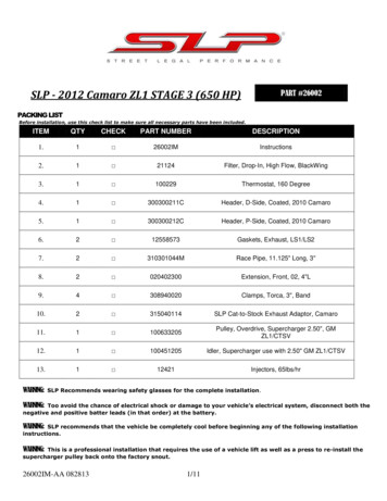
STEP 2. Loosen and remove all accessory drive belts from the engine. Remove the alternator or alternator brackets if any of thebrackets are attached to the intake manifold. Remove any other accessory or accessory brackets that are attached to the intakemanifold. Remove the fan from the water pump.STEP 3. In many cases it will be easier to install the lower pulley to the crankshaft if the radiator and/or the fan shroud isremoved from the vehicle.STEP 4. Remove the distributor and spark plug wires from the engine, noting the position of the distributor and rotor beforeremoval to permit easy reinstallation of the distributor. If the distributor uses a separate coil mounted on the intake manifold,remove the coil and its mounting bracket.STEP 5. Disconnect the throttle linkage or cable from the carburetor. Disconnect the transmission linkage, if any, from thecarburetor. Disconnect the fuel line from the carburetor. Temporarily plug the fuel line. Disconnect any other linkage or wiringthat is connected to the carburetor or intake manifold.STEP 6. Remove the bolts holding the intake manifold to the cylinder heads and remove the intake manifold. Remove all tracesof the old gaskets and sealer from the cylinder heads and cylinder block. If the same carburetor is to be used with thesupercharger, remove it from the intake manifold and set it aside.INSTALLATIONWARNING: Be very careful that no foreign objects are allowed to enter the supercharger. Anything that comes between therotors and the housing or between the two rotors can cause serious damage to the supercharger. Do not remove the coveringfrom the outlet port of the supercharger, until just before it is bolted to the intake manifold. Do not remove the covering from theintake port, until the carburetor is ready to be bolted on.250 Powerchargers use a Gilmer (toothed) belt to drive the blower. See the supplemental instructions for details of the specifickit.STEP 1. (Powercharger). Remove the bolts that secure the crankshaft pulley to the damper. The center bolt from the dampermust also be removed on small block Chevrolet V8s. Install the supplied supercharger drive pulley together with any spacersthat are supplied with the kit inside of the stock stamped steel crankshaft pulley. Fit the pilot on the pulley or spacer into thecenter of the stock steel pulley, and the pilot of the drive pulley into the spacer, if there is one, and align the bolt holes. Put thesupplied bolts through the pulley and spacer (if there is one) into the crankshaft. Use thread sealer on these bolts. Tighten thebolts. The small block Chevrolet kits require the removal of the center bolt that secures the harmonic balancer to the engine, buton other engines the center bolt is not removed. On small block Chevrolet kits install the supplied center bolt and tighten it to 75ft./lbs. See Figure 1.Figure 13
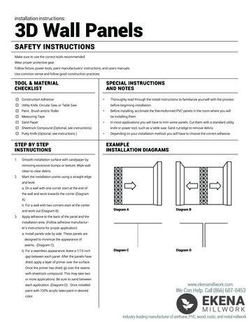
STEP 2. Prepare the intake manifold for installation. Install the thermostat into the manifold, and bolt on the thermostat housing.Use a new thermostat gasket when installing the thermostat housing and always use a thermostat or a water restrictor. 250Powerchargers include a new thermostat housing which is mounted on the front face of the intake manifold. The thermostathousing has an “O” ring seal, so no gasket is required.Remove the heater hose fitting(s), water pump bypass fittings and the temperature gauge sender from the old intake manifoldand install in the similar location in the Holley intake manifold. Install pipe plugs in the unused water opening(s) in the manifold.The 1/8" pipe threaded hole on the manifold is for a manifold pressure gauge and the distributor vacuum advance/boost retard.If a gauge is not being used, this hole should be plugged with a 1/8 NPT pipe plug.STEP 3. Install the supplied new intake manifold gaskets. Use the original intake manifold hold down bolts. If the distributor goesthrough the intake manifold, check that it fits correctly before tightening the manifold bolts. Leave the distributor in place whilethe bolts are being tightened. Tighten the intake manifold hold down bolts in the sequence specified by the manufacturer and totheir specified torque. It is important to follow the tightening sequence and torque readings accurately to ensure that themanifold is not distorted. In some cases where there is a tight clearance next to a manifold bolt, 12 point or socket head screwsmay need to be used.TOOLS REQUIRED:Ratchet or Speed HandleTorque Wrench (100 lb./ft.)Sockets 7/16”, 1/2”, 9/16”, & 5/8”Extensions 3” or 4”Open End/Box Wrench 3/8”, 7/16”, 1/2”, 9/16”, & 5/8”Allen Wrench 3/8”Gasket ScraperSmall block Chevrolet and Ford blower kits with the 144 cid blower have provision for an exhaust crossover for manifold heatand exhaust gas recirculation (EGR). There is a mounting pad on the Holley intake manifold for the EGR valve. A block off plateis installed on the pad that can be removed to mount the EGR valve if it is being used. The exhaust gas for the EGR valvecomes from the exhaust heat crossover in the intake manifold. If you are not using the EGR valve and if you do not use thevehicle in extremely cold conditions, the exhaust crossover passage can be blocked with steel shims at both cylinder heads. Thedriveability of the supercharger is very good without exhaust heat under all but the very coldest conditions. If you block theexhaust heat crossover, also secure the exhaust heat valve in one of the exhaust manifolds in the open position. Blocking theexhaust heat will provide approximately 10-15 HP gain on an average V8.The 250 Powercharger with Gilmer belt drive has a pop off valve mounted on the right hand side of the intake manifold. Installthe pop off valve onto the intake manifold after the manifold is bolted to the engine. Check to see that the gasket is attached tothe back side of the pop off valve plate. Place the plate on the manifold and then screw in the two studs. Put the two springsover the studs. Put the spring retainers into the outer end of the springs and screw the lock nuts onto the studs. Tighten the nutsuntil you have a spring height of 1-1/2" on each spring.STEP 4. Reinstall radiator if removed. Connect upper radiator hose to the thermostat housing and connect the heater hose(s).You may need to use a different upper radiator hose to clear the supercharger drive housing. Fill the cooling system and checkfor leaks.STEP 5 (Powercharger). Prepare the supercharger for installation. Remove the bolt and washer on the end of the superchargerinput shaft. Remove the plastic shipping cover from the input shaft. You may find some oil residue around this area. This is gearoil, which has leaked down the keyway of the input shaft. Put the drive pulley you have chosen and the 3/16 x 3/16 x 3/4 key onto the input shaft. Secure with the bolt and washer. We suggest that you use a little Loctite on the pulley retaining bolt threads.Also put some gasket sealer on the underside of the washer to prevent oil seeping out of the keyway. Torque the bolt to 30ft./lbs. Use a clean rag between the rotors to keep the shaft from turning. Make sure to remove the rag after tightening.Install the carburetor adapter on the 250 Powercharger. Install the gasket and screws supplied with the adapter. Tighten thescrews to 10 ft./lbs. After installing the adapter feel inside of the rotor housing to be sure that the ends of the eight screws do notproject through into the bore of the rotor housing.To check the oil level, first tilt the supercharger forward to be sure that oil flows around the front bearing. Then set thesupercharger flat on a bench. Use the new oil level sight window to check the level. (See Figure 2.) The oil level should be up tothe bottom of the hole. If the oil level is low, fill with SAE 80-90 gear lube. Because of the internal baffles inside of the gear case,the oil that is poured into the blower will go in very slowly. After pouring more oil into the fill hole wait two minutes beforechecking the fill level.4
Figure 2STEP 6 (Poly-V belt). A bracket for the idler is attached to the drive housing of the supercharger. There are two basic idlerassemblies that are used on almost all kits. The idler for blowers with the standard input location has one spring loaded idlerbolted to it (see Figure 3). The idler for blowers with an offset input (used on Ford V8 engines to clear the distributor) have afixed idler and a spring loaded idler. The spring-loaded idler is bolted to the cast mounting bracket (see Figure 4). Both types ofmounting brackets have a number of holes in them for locating Only two of the holes are used for the mounting bolts for thespring loaded idler/tensioner. These holes allow for several different locations for the idler assembly, and are used for differentsizes of driven (upper) pulleys.The idler assembly should be bolted to the support bracket with the two Allen head screws supplied with the kit. The preliminarylocation for the spring loaded idler is shown on the supplemental instructions for the particular blower kit. The two screws thathold the spring loaded idler in place go through either two holes in the upper row or two holes in the lower row on the supportbracket and then screw into either the upper or lower two tapped holes on the idler mounting pad. Mount the idler and tightenthe screws, but do not use the thread sealer at this time. The supercharger should now look like Figure 3 or 4. Be sure that thebolts securing the support bracket to the drive housing are also tight. The nut on the threaded rod extending from the end of theidler assembly should be fully tightened to pull the idler all of the way in.5
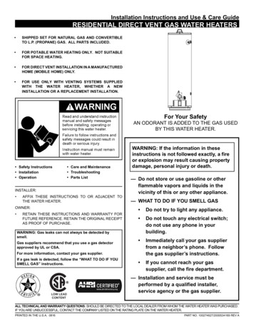
Figure 3Figure 4STEP 6 (250 Gilmer belt). The idler support assembly bolts to the front of the intake manifold. The support plate is secured withfour 3/8-16 flat head Allen screws. The screws go through the idler support plate, through the four aluminum spacer tubes, andscrew into the front of the intake manifold. Tighten the screws to 25-35 ft/lbs. (See Figure 5.)6
Figure 5STEP 7. Remove cardboard cover from the bottom of the supercharger and clean the surface. Check the flatness of the intakemanifold by placing the supercharger on the manifold and rocking it. If the manifold is flat, the supercharger will not rock. Onolder or rebuilt engines there may be some rocking. If there is more than .010" rocking, the supercharger housing may becomedistorted when it is bolted down. This can be checked by placing a feeler gauge between the bottom of the rotor housing and theintake manifold or by using a straightedge.A gasket is used between the intake manifold and the blower on all blowers. The 250 Powercharger formerly used an O-Ringset into a groove in the top of the intake manifold. This has been replaced with a gasket for better sealing. Some intakemanifolds may have a machined groove for an O-Ring, but these will seal correctly with the supplied gasket.For Powerchargers, install the four 7/16" x 7" bolts, or three 6-3/8" and one 8" studs for blowers with offset input shafts, throughthe mounting holes in the supercharger. Put the supplied flat washers under the heads of the bolts. Use thread sealer on thesebolts. Tighten the bolts or nuts. Do not tighten the bolts or nuts to over 10 ft./lbs., or the threads in the intake manifold may strip,or the blower may lock up.If the manifold is not completely flat, there will be an increase in the torque required to turn the blower, usually at ninety degreeintervals in each complete revolution of the input shaft. If the torque to turn the input shaft is not over 25 in./lbs. at these tightspots, the Teflon seals will wear in during the first few miles of driving. If the turning torque is over 25 in./lbs., then loosen onehold down bolt at a time to see which one is causing the blower to bind up. Leave this one bolt at a lower torque level, but atleast 5 ft./lbs. for the Powercharger, while the blower is being run in and tighten it later when the Teflon has seated.STEP 8. Reinstall the stock brackets and accessories that attach to the intake manifold. The 144 and 174 manifolds areequipped with mounting bosses to accommodate most standard OEM parts from your stock manifold. . Because of the largersize of the 250 Powercharger it may be necessary to modify some brackets and accessories. Connect heater hoses and anyother plumbing that connects to the manifold.STEP 9 (Poly-V belt). Install and tighten the accessory belts. Install the Poly-V belt over the lower drive pulley, driven pulley,and idler pulley(s). Loosen the nut on the threaded rod on the back of the idler to let the idler pulley tension the belt. When thenut is loose, measure the distance between the pulley support and the end of the fixed tube of the idler as shown in Figure 6.This dimension should be between .30" and .50" (5/16" and 1/2"). If the measured dimension is outside of this range, the idlerwill have to be moved in or out. Due to manufacturing tolerances on belts, the final position of the idler may be different than thepreliminary location.After the idler is correctly located and the dimension is between .30" and .50", tighten the nut on the threaded rod to removetension from the idler. Then apply the supplied thread sealer to the two mounting screws and tighten securely. Remove the nutfrom the threaded rod and leave it off.On some late model engines the idler may interfere with the alternator. If this happens you will need to use a slightly longeralternator belt.7
Figure 6STEP 9 (Gilmer belt). Install all belt-driven engine accessories and drive belts before installing the blower drive. Put the 5/8-11socket head bolt through the center of the idler pulley assembly. Put the bolt through the slot in the idler support plate and putthe nut on the back side of the plate. Align the nut with the slot and tighten the bolt finger tight with the pulley slid as far inboardas possible. Put the blower drive belt over the drive and driven pulleys and over the idler. Make sure that the belt is seated in thegrooves in the upper and lower pulleys. Slide the idler pulley out until there is about 1-1/2" of slack in the belt when the blower iscold. Tighten the bolt. The belt tension will be rechecked later after the engine has been warmed up. There must be a minimumof 1/2-5/8" slack in the belt when the engine is hot, or the blower or crankshaft can be over stressed. (See the included GilmerBelt Installation and Adjustment Instruction sheet for more details.STEP 10. Install the fan if required. It may be necessary to put a fan spacer between the fan and the water pump so that the fanwill not hit the supercharger drive belt. Allow at least 3/8" between the fan blades and the rear side of the radiator and fanshroud to avoid contact. You may need to modify an available fan spacer to achieve proper fan clearance. We do notrecommend using a large viscous drive clutch fan with a blower. The addition of a fan spacer to the system together with thehigher engine speeds frequently used with a supercharger seems to aggravate the possibility of breakage of the water pump. Alighter weight flex fan is recommended, particularly for truck usage. Also make sure that the pump pulley, spacer and fanassembly are concentric and balanced.Some applications may not have enough room for a conventional fan with the supercharger installed. In this case electriccooling fan(s) can be used.STEP 11. Remove the cardboard cover(s) from the top of the blower. Install the carburetor(s) on the top of the supercharger. If aspreadbore is being used install a carburetor gasket at least 1/8" thick, preferably the stock GM carburetor spacer/insulator. Thisspacer/insulator assures a complete seal between the carburetor and the top of the blower. Some gaskets have a channel at theback that can cause a vacuum leak. Check the carburetor gasket and spacers that you are using to be sure that they fully sealto both the bottom of the carb and to the top of the blower. Holley spread bore carburetors will not always seal to the top of theHolley blower using standard gaskets. If there is an air leak between the carburetor and the blower, the engine will not runcorrectly and it will probably be lean. If you are using the Holley #90747 throttle cable bracket, install it between the carburetorand the blower when the carburetor is installed. Be sure to use a cork or rubber gasket between the air cleaner and thecarburetor, or excessive noise may result.Check to see that the secondary throttle blade of the spreadbore carburetor can open fully without hitting the blower. The 1/8"gasket or spacer should be enough to avoid this problem, but it should be checked to be sure. If a Holley carburetor with theREO accelerator pump is used, it may be necessary to use two gaskets, so that the pump will not hit the supercharger housing.Check all carburetor secondary throttle plates in the full open position to make sure they don’t hit the blower housing. If they do,space the carburetor up with the appropriate spacer or gaskets. If you have adequate hood clearance it’s not a bad idea toutilize a non-metallic spacer between the carb and blower as a heat insulator. These are available from several manufacturers.8
250 Powerchargers use either one or two 4 bbl carburetors, depending on the carburetor adapter installed on the blower. Thesingle carburetor installation is similar to the smaller blowers, as described above.For 250 Powerchargers with two carburetors, the mounting pad is drilled so that the carburetors can be mounted either fore andaft or side saddle. The only carburetors that will fit when mounted fore and aft are the Holley 1850 or other similar modelHolleys. All other carburetors must be mounted side saddle.STEP 12. Connect the throttle linkage to the carburetor. Some cable throttle linkages and most rod-type linkages will requirereworking to properly operate the throttle lever. Be sure that the carburetor is wide-open when the accelerator pedal is pushed tothe floor, and that the throttle closes fully when the accelerator pedal is released.Vehicles equipped with a TH200, TH200-R4, TH700-4R, C-3, AOD, or A4LD transmission have the shifts controlled by amechanical linkage or cable between the carburetor and the transmission. This linkage or cable must be connected to thecarburetor in exactly the same manner as the stock vehicle for the transmission to operate correctly. On GM transmissions theproper operation of the throttle cable is essential for correct operation and life of the transmission. Vehicles equipped withTH350, C-4, C-5 or C-6 transmission use a mechanical linkage or cable between the carburetor and transmission to controltransmission kickdown. These cables and linkages must be adjusted for correct operation of the kickdown at wide-open throttle.The TH400 transmission uses an electric switch to control kickdown.For GM cars with a single carburetor Holley offers a special cable bracket (#90747) that mounts between the superchargerhousing and the carburetor. It allows the late model GM factory throttle cable (or kickdown cable), transmission cable, andcruise control cable to be relocated to work with the repositioned carburetor on the supercharger.For 250 Powerchargers with two carburetors Holley offers a throttle linkage kits. #93167 is for 250 Powercharger with sidesaddle carburetors. This kit uses a bellcrank on the side of the blower to connect to the vehicle throttle linkage.If your vehicle is equipped with a TH-350 or TH-400 automatic transmission, the shifts are controlled by a vacuum modulatorthat senses manifold vacuum, while kickdown is controlled by linkage, a cable or a switch. In most cases the vacuum modulatorwill work satisfactorily when hooked up to the carburetor.STEP 13. Run a fuel line from the fuel pump to the carburetor. Be sure that the fuel line is away from the exhaust or any movingparts and that it is well secured. Use only approved fuel line. Install a new fuel filter between the fuel pump and the carburetor.See the Holley Supercharger Technical Manual for fuel line and pump sizes. Holley's fuel line kit #93171 can be used for sidemount Holly double pumper carburetors and #93172 can be used for side mount Holley vacuum secondary carburetors.STEP 14. Recheck the distributor and install the spark plug wires. Be sure that the distributor is installed in the same positionthat it was in when it was removed. Use the distributor hold down clamp from the old manifold. A stud can be used to secure thehold down clamp. Incorrect ignition timing can cause backfiring, which may result is severe blower damage. See the HolleySupercharger Technical Manual for timing tips.STEP 15. Connect power brake vacuum hose and other vacuum hoses to the vacuum fittings on the carburetor or to the port onthe passenger’s side of the rotor housing under the carburetor. (The pipe plug must be in this port if it is not connected to avacuum line.) The power brakes must not be connected to the intake manifold. The crankcase vent hose (or the PCV valve)must have a separate vacuum connection to the carburetor or to the port on the rotor housing. The crankcase
The Holley Powercharger is intended for use on engines with compression ratios of up to 9.50:1 with a maximum blower pressure of 5-6 psi. Higher boost pressures will require lower compression ratios or a boost retard. The Powercharger is available in three different blower sizes, 144 cu.in ./revolution, 174 cu.in./revolution and 250 .