Transcription
TECHNICAL MANUALMANUALGMS8 33-3/8" Gas Furnace Units80% AFUE, Single Stage,Multi-Speed, Upflow Horizontal Refer to Service Manual RS6612006 for troubleshooting information. Refer to the appropriate Parts Catalog for part number information. Model numbers listed on page 3.This manual is to be used by qualified, professionally trained HVAC techniciansonly. Goodman does not assume any responsibility for property damage orpersonal injury due to improper service procedures performed by an unqualifiedperson.Copyright 2013 Goodman Manufacturing Company, L.P.RT6621031r2November 2013
PRODUCT IDENTIFICATIONThe model and manufacturing number are used for positive identification of component parts used in manufacturing.Please use these numbers when requesting service or parts information.GMPRODUCTTYPE:G: GoodmanS8040FURNACETYPES: Single-Stage/Multi-SpeedAFUE8: 80%WARNINGNOMINAL INPUT040: 40,000 Btuh060: 60,000 Btuh080: 80,000 Btuh100: 100,000 Btuh120: 120,000 Btuh140: 140,000 BtuhXAIRFLOWCAPABILITY3: 12004: 16005: 2000AAMAJOR REVISIONA: Initial ReleaseMINOR REVISIONA: Initial ReleaseADDITIONALFEATURESN: Natural GasX: Low NOxHIGH VOLTAGE!Disconnect ALL power before servicing or installing this unit. Multiple powersources may be present. Failure to do so may cause property damage, personalinjury or death.Goodman will not be responsiblefor any injury or property damagearising from improper service or service procedures. Ifyou install or perform service on this unit, you assumeresponsibility for any personal injury or property damagewhich may result. Many jurisdictions require a license toinstall or service heating and air conditioning equipment.WARNINGACABINETWIDTHA: 14"B: 17-1/2"C: 21"D: 24-1/2"SUPPLY TYPEM: Upflow/Horizontal23Installation and repair of this unitshould be performed ONLY byindividuals meeting the requirements of an "entry leveltechnician" as specified by the Air-Conditioning, Heating,and Refrigeration Institute (AHRI). Attempting to install orrepair this unit without such background may result inproduct damage, personal injury or death.WARNING
PRODUCT IDENTIFICATIONThe model and manufacturing number are used for positive identification of component parts used in manufacturing.Please use these numbers when requesting service or parts 1405DNCC*These models available in Natural Gas and Low NOx.WARNINGThe United States Environmental Protection Agency (“EPA”) has issued various regulations regarding the introduction and disposal of refrigerants introduced into this unit. Failure to followthese regulations may harm the environment and can lead to the imposition of substantial fines.These regulations may vary by jurisdiction. Should questions arise, contact your local EPA office.Do not connect or use any devicethat is not design certified by Goodman for use with this unit. Seriousproperty damage, personal injury, reduced unit performance and/or hazardous conditions may result from theuse of such non-approved devices.WARNINGTo prevent the risk of propertydamage, personal injury, or death,do not store combustible materials or use gasoline orother flammable liquids or vapors in the vicinity of thisappliance.WARNING3
PRODUCT DESIGNGeneral OperationThe GMS8 furnaces are equipped with an electronic ignitiondevice used to light the burners and an induced draft blowerto exhaust combustion products.An interlock switch prevents furnace operation if the innerblower door is not in place. Keep the blower access door inplace except for inspection and maintenance. (See illustration on pages 5 and 6.)This furnace is also equipped with a self-diagnosing electronic control module. In the event a furnace component isnot operating properly, the control module LED will flash onand off in a factory-programmed sequence, depending onthe problem encountered. This light can be viewed throughthe observation window in the blower access door. Refer tothe Troubleshooting Chart for further explanation of the LEDcodes and Abnormal Operation - Integrated Ignition Controlsection in the Service Instructions for an explanation of thepossible problem.The rated heating capacity of the furnace should be greaterthan or equal to the total heat loss of the area to be heated.The total heat loss should be calculated by an approvedmethod or in accordance with “ASHRAE Guide” or “ManualJ-Load Calculations” published by the Air Conditioning Contractors of America.*Obtain from: American National Standards Institute 1430Broadway New York, NY 10018Location Considerations The furnace should be as centralized as is practicalwith respect to the air distribution system. Do not install the furnace directly on carpeting, tile, orcombustible material other than wood flooring. When installed in a residential garage, the furnacemust be positioned so the burners and ignition sourceare located not less than 18 inches (457 mm) abovethe floor and protected from physical damage by vehicles.Notes:WARNINGTO PREVENT POSSIBLE PERSONAL INJURY OR DEATH DUE TO ASPHYXIATION,THIS FURNACE MUST BE CATEGORY I VENTED. DO NOT VENT USINGCATEGORY III VENTING.Category I Venting is venting at a non-positive pressure. Afurnace vented as Category I is considered a fan-assistedappliance and the vent system does not have to be “gastight.” NOTE: Single stage gas furnaces with induced draftblowers draw products of combustion through a heat exchanger allowing, in some instances, common venting withnatural draft appliances (i.e. water heaters). All installationsmust be vented in accordance with National Fuel Gas Code4NFPA 54/ANSI Z223.1 - latest edition. In Canada, the furnaces must be vented in accordance with the National Standard of Canada, CAN/CSA B149.1 and CAN/CSA B149.2 latest editions and amendments.NOTE: The vertical height of the Category I venting systemmust be at least as great as the horizontal length of theventing system.Accessibility Clearances (Minimum)Unobstructed front clearanace of 24" for servicing is recommended.MINIMUM CLEARANCE TO COMBUSTIBLE MATERIALS - INCHESSidesRearFront*103VentSWB61Top1* 24" clearnace for serviceability recommended.** Single Wall Vent (SW) to be used only as a conncetor.Refer to the venting tables outlined in the Installation Manual foradditional venting requirements.Note: In all cases accessibility clearance shall take precedence over clearances from the enclosure where accessibility clearances are greater. All dimensions are given in inches.High Altitude DerateIMPORTANT NOTE: The furnace as shipped requires nochange to run between 0 - 5500 feet. Do not attempt toincrease the firing rate by changing orifices or increasingthe manifold pressure below 5500 feet. This can cause poorcombustion and equipment failure.High altitude installations above 5500 feet may require botha pressure switch and an orifice change. These changesare necessary to compensate for the natural reduction inthe density of both the gas fuel and the combustion air athigher altitude.For installations above 5500 feet, please refer to your distributor for required kit(s). Contact the distributor for a tabular listing of appropriate manufacturer’s kits for propane gasand/or high altitude installations. The indicated kits must beused to insure safe and proper furnace operation. All conversions must be performed by a qualified installer, or serviceagency.
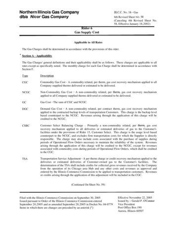
COMPONENT IDENTIFICATION1 Tubular Heat Exchanger2 Pressure Switch3 Flue Pipe Connection4 Induced Draft Blower?5 Gas LineEntrance6 Gas Valve7 Rollout Limit8 Junction Box9 Wiring HarnessGrommetGas ManifoldGas Line Entrance(Alternate)Inshot BurnerTransformerCirculator BlowerBlower DoorInterlock SwitchNote: Primary Limit Not ShownIntegrated Control ModuleUpflow/Horizontal1Tubular Heat Exchanger9 Wiring Harness Grommet2Pressure Switch10 Gas Manifold3Flue Pipe Connection11 Inshot Burner4Induced Draft Blower12 Transformer5Gas Line Entrance13 Integrated Control Module6Gas Valve14 Blower Door Interlock Swtich7Rollout Limit15 Circulator Blower8Junction Box16 Gas Line Entrance (Alternate)5
PRODUCT DIMENSIONSGMS8Alt. Gas InletAlt. Gas InletAlt. High VoltageHigh Voltage InletLow VoltageAlt. LowVoltageM ODELAB1412 - 1/217 - 1/2162119 - 1/224 - ***GMS80805C***GMS81005C***GMS81205D***GM S81405DN**6
GMS8[040-100]BBGMS81205D*BAPRODUCT DIMENSIONSGMS81405DNCCP re ssure S w itch Trip P ointsModelTrip PointID Blow erPressureSw itchID Blow erPressureSw itchPart #GM S80403A*BB-0.70B1370158GM S80603A*BB-0.75B1370179GM S80604B*BB-0.75B1370179GM S80804B*BB-0.70B1370158GM S80805C*BB-0.75B1370179GM S81005C*BB-0.70B1370158GM 42For installations in Canada, the GMS furnaces are certifed only to 4,500 ft.* Negative pressure readings are in inches of water column (*w.c.)P RIM ARY LIM ITPa r t Num ber2016290120 1 6 2 9 0 42 0 1 62 9 0 3Open Se tting ( F)210150160GM S8 0 40 3 A* BB1------GM S8 0 60 3 A* BB---1---GM S8 0 60 4 B* BB---1---GM S8 0 80 4 B* BB---1---GM S8 0 80 5 C* BB------1GM S8 1 00 5 C* BB---1---GM S8 1 20 5 D* BA------1GMS 81 4 0 5 DNCC------1ROLLOUT LIM IT SW ITCHESAUXILIARY LIM IT S W ITCHESPa r t Num be r0 1 3 0 F00 0 3 8Ope n Se tting ( F)120GM S80403A*BB1GM S80603A*BB1GM S80604B*BB1GM S80804B*BB1GM S80805C*BB1GM S81005C*BB12GM S81205D*BA12GMS 8 14 0 5 DNCC1Pa rt Num be r1 0 1 2 3 5 29Ope n Se tting ( F)300GM S 80 4 0 3 A*BB2GM S 80 6 0 3 A*BB2GM S 80 6 0 4 B*BB2GM S 80 8 0 4 B*BB2GM S 80 8 0 5 C*BB2GM S 81 0 0 5 C*BB2GM S 81 2 0 5 D*BAGM S8 1 4 0 5 DNCC7
PRODUCT DESIGNThermostats:It is recommended that a single-stage heat, non-power robbing thermostat be used. Refer to the product marketingliterature for a complete list of thermostats ammableCoolHeatBatt. Powered Batt. Bkup1213406*Man. Or AutoYes23NoNo1213407Man. ChangeoverYes22YesYes1213411Man. ChangeoverNo22YesNo*1213406 is the recommended model for the G*S* furnaces when used with a heat pump in a fossil fuel application.It is NOT for use with the G*S8 as a sole heating source. 1213406 thermstats are 24V powered with batterybackup.Filters are required with this furnace and must be provided by the installer. The filters used must comply with UL900 orCAN/ULCS111 standards. Installing this furnace without filters will void the unit warrantyUpflow FiltersCabinetWidth(in.)AllSIDE RETURNApprox.NominalFlowAreaFilter Size(in.)(in2)16 x 25 x 1400BOTTOM RETURNApprox.CabinetNominalFlowAreaWidthFilter Size(in.)(in.)(in2)17-1/214 x 25 x 13502116 x 25 x 140024-1/220 x 25 x 1500Refer to Minimum Filter Area tables to determine filter area requirement. NOTE: Filters can also be installed elsewhere inthe duct system such as a central return.MINIMUM FILTER SIZES for DISPOSABLE FI LTERSFURNACE I NPUT40M60M80M100M120M140MFILTER SIZE320 in 2483 in 2640 in 22800 in2738 in2738 inDISPOSABLE NOMINAL 300 F.M. FACE VELOCITY8
GMS8[040-100]BBGMS81205D*BAFURNACE SPECIFICATIONSTem perature Rise ( Rated External Static (" w.c.)GMS80804B*BBA.F.U.E.GMS80604B*BBO utput (US) High FireGMS80603A*BBBtuh Input (US) High FireGMS80403A*BBM O 0096,000112,00080%80%80%80%80%80%80%80%.20 - .50.20 - .50.20 - .50.20 - .50.20 - .50.20 - .50.20 - .50.20 - .5025 - 5525 -5520 - 5035 - 6535 - 6535 - 6540 - 7040 - 70High Stage Pressure Sw itchTrip Point (" w .c .)-0.70-0.75-0.75-0.70-0.75-0.70-0.80-0.80Blow er W heel (D" x W ")10 X 610 x 610 x ransform er (VA)4040404040404040Heat Anticipator (Am ps)0.70.70.70.70.70.70.70.7Prim ary Lim it Setting ( F)210 150 150 150 160 150 160 160 Auxiliary Lim it Setting ( F)120 120 120 120 120 120 120 120 Rollout Lim it Setting ( F)300 300 300 300 300 300 300 300 Gas Supply Pressure(Natural/Propane) (" w.c.)7 / 117 / 117 / 117 / 117 / 117 / 117 / 117 / 113.5 / 103.5 / 103.5 / 103.5 / 103.5 / 103.5 / 103.5 / 103.5 / 10#45 / #55#45 / #55#45 / #55#45 / #55#45 / #55#45 / #55#45 / #55#43 / #552334456644444444848898106114118130130Blow er Horsepow erBlow er SpeedsMax C FM @ 0.5 E.S.P.Power SupplyMinim um C ircuit Am pacity (MCA)Maxim um O vercurrent Devic e(1)(2)Manifold Pressure(Natural/Propane) High Stage (" w.c.)O rifice Size (Natural/Propane)Num ber of BurnersVent Connector D iam eter (inc hes)Shipping W eight (lbs.)(3 )(1)Wire size should be determined in accordance with National Electrical Codes. Extensive wire runs will require larger wire sizes.Maximum Overcurrent Protection Device: May use Time Delay Fuse or HACR type Circuit Breaker of the same size as noted.(3)See Installation Instructions for appropriate vent diameter, length and number of elbows.(2)1.These furnaces are manufactured for natural gas operation. Optional Kits are available for conversion to propane gas operation.2.For elevations above 2000 ft. the rating should be reduced by 4% for each 1000 ft. above sea level. The furnace must not be derated, orificechanges should only be made if necessary for altitude.3.The total heat loss from the structure as expressed in TOTAL BTU/HR must be calculated by the manufactures method in accordance with the"A.S.H.R.A.E. GUIDE" or "MANUAL J-LOAD CALCULATIONS" published by the AIR CONDITIONING CONTRACTORS OF AMERICA. The totalheat loss calculated should be equal to or less than the heating capacity. Output based on D.O.E. test procedures, steady state efficiency timesoutput.4.Minimum Circuit Ampacity calculated as: (1.25 x Circulator Blower Amps) I.D. Blower Amps.Unit specifications are subject to change without notice. ALWAYS refer to the unit's serial plate for the most up-to-date general and electrical information.9
GMS8[040-100]BBGMS81205D*BABLOWER PERFORMANCE SPECIFICATIONSGMS81405DNCC(CFM & Te m pe ra ture Rise vs. Ex te rna l S ta tic P re ssure )ModelHeating SpeedA s ShippedEXTER N AL STATIC PR ESSUR E (Inches Water C olum n )Ton s ACMotorSpe edat 0 .5 "0.10 .20.30.40 .50 .60 .70.8ESPC FM R ISE C FM R ISE C FM R ISE CFM R ISE C FM R ISE C FM CFM CFMH IGH3 .01 52 1----146 6----14 14----1 37 3----129 8----12 43 1 164 1 07 5*MS8 04 03A*BBMED2 .51 16 026116 02611 32261 12 126108 22710 4299 79 25(MED IUM)MED -L O2 .09 61319 553194 8319 32329 133388 282 18 03L OW1 .57 81387 853878 1387 73387 613274 571 66 68H IGH3 .01 42 231135 23313 07341 19 737115 738*MS8 06 03A*BBMED2 .51 09 840108 14110 51421 03 943102 14410 92 1 07598 392 48 689 83(MED IUM)MED -L O2 .09 19489 134989 2508 47----8 29----81 879 27 28L OW1 .57 58----7 41----74 1----7 33----6 99----67 764 96 26H IGH4 .02 13 421210 02120 42221 97 523188 32417 86 1 700 1 60 1*MS80 60 4B*BBMED3 .51 66 827166 32716 56271 64 527161 62815 49 1 492 1 39 1(MED IUM)MED -L O3 .01 41 931142 63114 26311 43 231141 93113 78 1 328 1 26 1L OW2 .51 13 439114 53911 66381 17 138116 03811 44 1 111 1 07 1H IGH4 .02 05 1----198 3----18 95----1 81 2----172 5----16 27 1 530 1 43 9*MS80 80 4B*BBMED3 .51 73 6----170 83516 52361 61 137154 03814 75 1 394 1 30 7(MED IUM)MED -L O3 .01 69 335166 83614 59411 42 941138 94313 39 1 274 1 20 4L OW2 .51 20 049118 55011 80501 17 351115 85111 25 1 125 1 08 0H IGH5 .02 29 0----222 9----21 55----2 04 7----196 0----18 37 1 712 1 58 4*MS80 80 5C *BBMED4 .01 85 2----182 0----17 77----1 71 9---164 13615 67 1 469 1 38 2(MED IUM)MED -L O3 .51 61 537159 23715 56381 51 639147 04014 05 1 346 1 23 5L OW3 .01 29 046128 54612 65471 23 548121 44911 74 1 044H IGH5 .02 32 3----222 5----21 20352 04 036197 43818 01 1 688 1 57 7*MS81 00 5C *BBMED4 .01 85 840184 74017 99411 74 442167 44415 77 1 493 1 39 9(MED IUM)MED -L O3 .51 59 646158 74715 71471 55 248149 35013 97 1 326 1 21 7L OW3 .01 29 157127 25812 61591 25 759120 56111 68 1 118 1 06 0H IGH5 .02 46 9----238 9----23 00----2 22 340213 14220 27 1 902 1 78 6*MS81 20 5D *BAMED4 .01 57 556155 85715 45581 51 359150 05914 19 1 354 1 27 1(MED IUM)MED -L O3 .51 40 263138 06413 43661 31 967129 66912 45 1 183 1 10 6L OW3 .01 20 0----118 6----11 61----1 12 7----108 2----10 42H IGH5 .02 46 942238 94323 00452 22 347213 14920 27 1 902 1 78 6GMS81 40 5D N CCMED4 .01 57 566155 86715 45671 51 369150 06914 19 1 354 1 27 1(MED IUM)MED -L O3 .51 40 2----138 0----13 43----1 31 9----129 6----12 45 1 183 1 10 6L OW3 .01 20 0----118 6----11 61----1 12 7----108 2----10 4299 599 59 049 269 26NOTES: CFM in chart is without filter(s). Filters do not ship with this furnace, but must be provided by the installer. All furnaces ship as hig-speed cooling. Installer must adjust blower cooling speed as needed. For most jobs, about 400 CFM per ton when cooling is desirable INSTALLATION IS TO BE ADJUSTED TO OBTAIN TEMPERATURE RISE WITHIN THE RANGE SPECIFIED ON THE RATING PLATE. The chart is for information only. For satisfactory operation, external static pressure must not exceed values shown on the rating plate. The shaded area insicatedranges in excess of maximum static pressure allowed when heating. The dashed (---) areas indicate a temperature rise not recommended for this model. At higher altitudes, a properly de-rated unit will have approximatley the same temperature rise at a particular CFM, while ESP at the CFM will be lower.10
TEMPERATURE RISE10203040506070308090100405060700600 CFM90100200022002400 CFM180016001400OUTPUT BTU/HR x 10008012001100100090070800FORMULAS110120130140BTU OUTPUT CFM x 1.08 x RISEBTU OUTPUTRISE BTU OUTPUT vs TEMPERATURE RISE CHART150BLOWER PERFORMANCE SPECIFICATIONS11
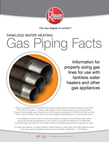
WIRING DIAGRAMSGMS8WARNING:DISCONNECT POWER BEFORESERVICING.WIRING TO UNIT MUST BEPROPERLY POLARIZED AND GROUNDED.INTEGRATEDCONTROL MODULEHUMIDIFIERXFMR (6)24 VACHUMIDIFIERGNDGND (8)CC2 GASVALVEMVC (9)R W YGM11654987121110YLRDYLBLBRRDGRRD2AUXILI ARYLIMITS11 5 VAC NEUTRALINTEGRATEDCONTROL MODULEGPS (10)HLI (7)WHLO (1)AUTO RESETPRIMARYLIMITCONTROLRRO2 (11)RO1 (5)MANUAL RESET ROLLOUTLIMIT CONTROL(S)(SINGLE CONTROL ON SOME MODELS)24 VAC40 VATRANSFORMERBRXFMR-HYLOR1115 VACYLRDFP (2)HOT TORBLWRATHECAPYLWHHEAT-HWHGR15 PIN PLUGON SOME MODELSBLOWER COMPARTMENTLINE-NLINE-HJUNCTION BOXBURNER COMPARTMENTCPRESSURESWITCHWHBKPRIMARY LIMITNOYLORRDDOORSWI TCH24 VACHUMIDIFIERBKDOOR SWITCHSWITCH LOCATED IN BLOWERCOMPARTMENT ON SOME MODELSRDCIR-NINTEGRATED CONTROL MODULEWHBRBRYLRDXFMRINTEGRATED CONTROL MODULEBRWH115VCICULATOR BLOWERORBKBKIGNBK (HI)BL (MED)OR (MED LOW)RD (LOW)WH (N)WHBK24VXFMR-NFLAME SENSORWHPUBKPU115 VAC HOT AND PARK TERMINALSLINE-HXFMR-HHEAT-HCOOL-HNOCPSO (4)TOMICROYXFMR (3)BLYLWHWHHIGH VOLTAGE!DISCONNECT ALL POWER BEFORE SERVICING OR INSTALLING THISUNIT. MULTIPLE POWER SOURCES MAY BE PRESENT. FAILURE TODO SO MAY CAUSE PROPERTY DAMAGE, PERSONAL INJURY OR DEATH.24V THERMOSTAT CONNECTIONS2ID BLOWERPRESSURESWITCHAUXILIARYLIMIT CONTROLSOR3MV (12)CDIAGNOSTICLEDFUSEWARNING:DISCONNECT POWERBEFORE SERVICING.WIRING TO UNITMUST BEPROPERLYPOLARIZEDAND GROUNDED.BKDISCONNECTNLGND1 Ø /60 HZ POWER SUPPLY WITHOVERCURRENT PROTECTION DEVICETO LAMESENSORGAS VALVELINE-NGNDLINE HPUINDUCED DRAFTBLOWERPUPUROLLOUT LIMITS(SINGLE CONTROL ON SOME MODELS)012STEADY ON NORMAL OPERATIONOFF CONTROL FAILURE1 FLASH SYSTEM LOCKOUT (RETRIES/RECYCLES EXCEEDED)2 FLASHES PRESSURE SWITCH STUCK CLOSED33 FLASHES PRESSURE SWITCH STUCK OPEN44 FLASHES OPEN HIGH LIMIT55 FLASHES FLAME SENSE WITHOUT GAS VALVE66 FLASHES OPEN ROLLOUT77 FLASHES LOW FLAME SIGNALCRAPID FLASHES REVERSED 115 VAC POLARITY/VERIFY GNDCOLOR CODES:YL YELLOWOR ORANGEPU PURPLEGR GREENBK BLACKPK PINKBR BROWNW H WHITEBL BLUEGY GRAYRD REDTO 115 VAC/ 1/60HZPOWER SUPPLY WITHOVERCURRENT PROTECTIONDEVICELOW VOLTAGE (24V)LOW VOLTAGE FIELDHI VOLTAGE (115V)EQUIPMENT GNDFIELD GNDFIELD SPLICEHI VOLTAGE FIELDSWITCH (TEMP.)JUNCTIONTERMINALINTERNAL TOINTEGRATED CONTROLPLUG CONNECTIONIGNITERSWITCH (PRESS.)OVERCURRENTPROT. DEVICENOTES:1. SET HEAT ANTICIPATOR ON ROOM THERMOSTAT AT 0.7 AMPS.2. MANUFACTURER'S SPECIFIED REPLACEMENT PARTS MUST BE USED W HEN SERVICING.3. IF ANY OF THE ORIGINAL WIRE AS SUPPLIED WITH THE FURNACE MUST BEREPLACED, IT MUST BE REPLACED W ITH W IRING MATERIAL HAVING A TEMPERATURERATING OF AT LEAST 105 C. USE COPPER CONDUCTORS ONLY.4. BLOWER SPEEDS MUST BE ADJUSTED BY INSTALLER TO MATCH THE INSTALLATIONREQUIREMENTS SO AS TO PROVIDE THE CORRECT HEATING TEMPERATURE RISE AND THECORRECT COOLING CFM. (SEE SPEC SHEET FOR AIR FLOW CHART)5. UNIT MUST BE PERMANENTLY GROUNDED AND CONFORM TO N.E.C. AND LOCAL CODES.0140F00119-CWiring is subject to change, always refer to the wiring diagram on the unit for the most up-to-date wiring.12
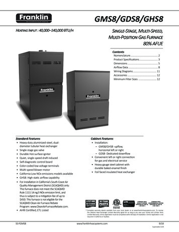
SCHEMATICSGMS8HIGH VOLTAGE!DISCONNECT ALL POWER BEFORE SERVICING OR INSTALLING THISUNIT. MULTIPLE POWER SOURCES MAY BE PRESENT. FAILURE TODO SO MAY CAUSE PROPERTY DAMAGE, PERSONAL INJURY OR DEATH.CIRCULATORBLOWERINDUCERCIRPARK PARK NEUHEAT COOLINDRK2RO2RO1THK3K1ROLLOUTSWITCHXFMRHOT24 TATAUXLIMITPRESSURESWITCHTYPICAL SCHEMATICGMS8 * MODEL FURNACESWR 50T55-289 INTEGRATED IGNITION CONTROLThis schematic is for reference only. Not all wiring is as shown above. Always refer to the appropriate wiring diagram for the unit being serviced.13
4 PRODUCT DESIGN NFPA 54/ANSI Z223.1 - latest edition. In Canada, the fur-naces must be vented in accordance with the National Stan-dard of Canada, CAN/CSA B149.1 and CAN/CSA B149.2 -