Transcription
GMS8/GDS8/GHS8Single-Stage, Multi-Speed,Multi-Position Gas Furnace80% AFUEHeating Input : 40,000–140,000 BTU/hContentsNomenclature. 2Product Specifications. 3Dimensions. 5Airflow Data. 8Wiring Diagrams. 11Accessories. 12Minimum Filter Sizes . 12Standard FeaturesCabinet Features Heavy-duty aluminized-steel, dualdiameter tubular heat exchanger Single-stage gas valve Durable Hot-surface igniter Quiet, single-speed draft induced Self-diagnostic control board Color-coded low-voltage terminals Multi-speed blower motor California Low NOx emissions models available GHS8: High static airflow capability For installation in California’s South Coast AirQuality Management District (SCAQMD) only:This furnace does not meet the SCAQMDRule 1111 14 ng/J NOx emission limit, andthus is subject to a mitigation fee of up to 450. This furnace is not eligible for theSCAQMD Clean Air Furnace RebateProgram: www.CleanAirFurnaceRebate.com. AHRI Certified; ETL Listed Installation:–– GMS8/GHS8 -upflow,horizontal left or right–– GDS8- Dedicated downflow Convenient left or right connectionfor gas and electrical service Heavy-gauge steel cabinet withdurable baked-enamel finish Foil faced insulated heat exchangerSS-FGMS8* Complete warranty details available from your local dealer or at www.franklinhvacsystems.com. To receivethe Lifetime Heat Exchanger Limited Warranty (good for as long as you own your home) and 10-Year PartsLimited Warranty, online registration must be completed within 60 days of installation. Online registration is notrequired in California or Québec.www.franklinhvacsystems.com9/18Supersedes 5/18
ndEngineeringG - Goodman BrandMajor / Minor RevisionsConfigurationNOxM - Upflow/HorizontalC - Downflow/HorizontalN - Natural GasD - Dedicated DownflowX - Low NOxH - High AirflowGas ValveCabinet WidthS - Single Stage, Single SpeedA - 14"C - 21"B - 17½" D - 24½"AFUEMaximum CFM80 - 80% AFUE3 - 1200 CFMMBTU/h24 - 1600 CFM040 - 40,000 BTU/h100 - 100,000 BTU/h060 - 60,000 BTU/h120 - 120,000 BTU/h080 - 80,000 BTU/h140 - 140,000 BTU/h5 - 2000 CFMwww.franklinhvacsystems.comSS-FGMS8
GMS8 Product 0140,000Natural Gas 2,000LP Gas ,0008080808080808080Heating CapacityAFUE ¹Available AC @ 0.5” ESPTemperature Rise Range ( F)3344555525 - 5520 - 5020 - 5035 - 6535 - 6535 - 6540 - 7040 - 7010” x 6”10” x 6”10” x 8”10” x 8”10” x 10”10” x 10”11” x 10”11” x 10”⅓⅓½½½½¾¾Circulator BlowerSize (D x W)Horsepower @1075 RPMSpeed44444444Vent Diameter ²4"4"4"4"4"4"4"4"No. of Burners23344566Min. Circuit Ampacity ³4.84.88.88.88.88.814.714.7Max. Overcurrent Device (amps) ⁴1515151515151515Ship Weight (lbs)848898106114118130130Electrical DataAll models available in California Low NOx-compliant versions (except GMS81405D*C*)¹ DOE AFUE based upon Isolated Combustion System (ICS)² Vent and combustion air diameters may vary depending upon vent length. Refer to the latest editions of the National Fuel Gas Code NFPA 54/ANSIZ223.1 (in the USA) and the Canada National Standard of Canada, CAN/CSA B149.1 and CAN/CSA B142.2 (in Canada).³ Minimum Circuit Ampacity (1.25 x Circulator Blower Amps) ID Blower amps. Wire size should be determined in accordance with National ElectricalCodes. Extensive wire runs will require larger wire sizes.⁴ Maximum Overcurrent Protection Device refers to maximum recommended fuse or circuit breaker size.May use fuses or HACR-type circuit breakers of the same size as noted.Notes All furnaces are manufactured for use on 115 VAC, 60 Hz, single-phase electrical supply. Gas Service Connection ½” FPT Important: Size fuses and wires properly and make electrical connections in accordance with the National Electrical Code and/or all existing local codes.SS-FGMS8www.franklinhvacsystems.com3
GDS8/GHS8 0060,00080,000100,00040,00060,00080,000Natural Gas Output32,00048,00064,00080,00032,00048,00064,000LP Gas UE ¹80808080808080Available AC @ 0.5” ESP334534525 - 5530-6035-6540 - 7020 - 5020 - 5035 - 6510” x 6”10” x 6”10” x 8”10” x 10”11” x 6”11” x 8”11” x 10”Heating CapacityTemperature Rise Range ( F)Circulator BlowerSize (D x W)Horsepower @1075 RPM1/31/31/23/41/23/43/4Speed4444444Vent Diameter ²4”4”4”4”4”4”4”No. of Burners2345234Min. Circuit Ampacity ³4.84.88.810.510.513.713.7Max. Overcurrent Device (amps) ⁴15151515151515Ship Weight (lbs)889210511390102117Electrical Data¹ DOE AFUE based upon Isolated Combustion System (ICS)² Vent and combustion air diameters may vary depending upon vent length. Refer to the latest editions of the National Fuel Gas Code NFPA 54/ANSI Z223.1(in the USA) and the Canada National Standard of Canada, CAN/CSA B149.1 and CAN/CSA B142.2 (in Canada).³ Minimum Circuit Ampacity (1.25 x Circulator Blower Amps) ID Blower amps. Wire size should be determined in accordance with National ElectricalCodes. Extensive wire runs will require larger wire sizes.⁴ Maximum Overcurrent Protection Device refers to maximum recommended fuse or circuit breaker size. May use fuses or HACR-type circuit breakers of thesame size as noted.Notes All furnaces are manufactured for use on 115 VAC, 60 Hz, single-phase electrical supply. Gas Service Connection ½” FPT Important: Size fuses and wires properly and make electrical connections in accordance with the National Electrical Code and/or all existing local codes.4www.franklinhvacsystems.comSS-FGMS8
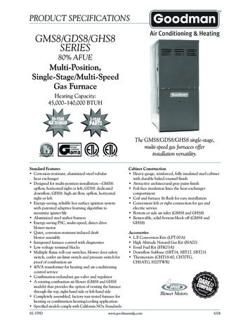
GMS8 DimensionsAlt. Flue Outlet — Horizontal Left1¾”17 16”AB19½” Alternate Gas Inlet 33⅜”Alt. Gas Inlet 27⅞”20”High-Voltage Inlet235 16”Alt. High Voltage15”13¼”Low-Voltage InletAlt. Low Voltage 23” 3”Notes Line voltage wiring can enter through the right or left side of furnace.Low-voltage wiring can enter through the right or left side of furnace. Conversion kits for high-altitude (4500 ft) natural gas operation are available.Contact your Franklin distributor or dealer for details.Minimum Clearances to Combustible 1”Top1”¹ 24” clearance for serviceability recommended.² Single Wall Vent (SW) to be used only as a connector. Refer to the latest editions of the National Fuel GasCode NFPA 54/ ANSI Z223.1 (in the USA) and the Canada National Standard of Canada, CAN/CSA B149.1 andCAN/CSA B142.2 (in Canada).Note: GMS8 approved for line contact in the horizontal position.SS-FGMS8www.franklinhvacsystems.com5
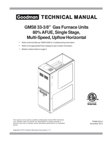
GDS8 DimensionsA28”19 33 ⅜”Gas Inlet18 ⅜”11 ⅜”ABNon-CombustibleFloor 1”19½”SBT21ModelNotes Line voltage wiring can enter through the right or left side of furnace.Low-voltage wiring can enter through the right or left side of furnace. Conversion kits for high-altitude (4500 ft) natural gas operation are available. Contact your Franklin distributor or dealer for details.Minimum Clearances to Combustible 1”Top1”¹ 24” clearance for serviceability recommended.² Single Wall Vent (SW) to be used only as a connector. Refer to the latest editions of the National Fuel GasCode NFPA 54/ ANSI Z223.1 (in the USA) and the Canada National Standard of Canada, CAN/CSA B149.1 andCAN/CSA B142.2 (in Canada).Note: GMS8 approved for line contact in the horizontal position.6www.franklinhvacsystems.comSS-FGMS8
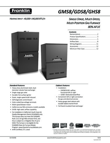
GHS8 DimensionsAlt. Flue Outlet — Horizontal Left1¾”17 16”AB Alternate Gas Inlet19½” 33⅜”Alt. Gas Inlet 27⅞”20”High-Voltage Inlet235 16”Alt. High Voltage15”13¼”Low-Voltage InletAlt. Low Voltage 23” 16”GHS80805CXB*21”19½”ModelNotes Line voltage wiring can enter through the right or left side of furnace.Low-voltage wiring can enter through the right or left side of furnace. Conversion kits for high-altitude (4500 ft) natural gas operation are available.Contact your Franklin distributor or dealer for details.Minimum Clearances to Combustible 1”Top1”¹ 24” clearance for serviceability recommended.² Single Wall Vent (SW) to be used only as a connector. Refer to the latest editions of the National Fuel GasCode NFPA 54/ ANSI Z223.1 (in the USA) and the Canada National Standard of Canada, CAN/CSA B149.1 andCAN/CSA B142.2 (in Canada).Note: GMS8 approved for line contact in the horizontal position.SS-FGMS8www.franklinhvacsystems.com7
GMS8 Airflow DataCFM & Temperature Rise vs. External Static C*MotorSpeedTonsAC¹HighExternal Static Pressure, (Inches Water 186----1,161----1,127----1,082----1,042995926¹ at 0.5” ESPNotes: CFM in chart is without filter(s). Filters do not ship with this furnace, but must be provided by the installer. If the furnace requires two return filters, thischart assumes both filters are installed. All furnaces ship as high-speed cooling and medium-speed heating. Installer must adjust blower cooling and heating speed as needed. For most jobs, about 400 CFM per ton when cooling is desirable. INSTALLATION IS TO BE ADJUSTED TO OBTAIN TEMPERATURE RISE WITHIN THE RANGE SPECIFIED ON THE RATING PLATE. This chart is for information only. For satisfactory operation, external static pressure must not exceed value shown on the rating plate. The dashed (----) areas indicate a temperature rise not recommended for this model. At higher altitudes, a properly derated unit will have approximately the same temperature rise at a particular CFM, while ESP at the CFM will be lower.8www.franklinhvacsystems.comSS-FGMS8
GDS8 Airflow DataCFM & Temperature Rise vs. External Static 1005C*BMotorSpeedTonsAC¹External Static Pressure, (Inches Water 1,366541,326561300122811390.60.70.8¹ at 0.5” ESPGHS8 Airflow DataCFM & Temperature Rise vs. External Static xternal Static Pressure, (Inches Water 025¹ at 0.5” ESPNotes CFM in chart is without filter(s). Filters do not ship with this furnace, but must be provided by the installer. If the furnace requires two return filters, thischart assumes both filters are installed. All furnaces ship as high-speed cooling and medium-speed heating. Installer must adjust blower cooling and heating speed as needed. For most jobs, about 400 CFM per ton when cooling is desirable. INSTALLATION IS TO BE ADJUSTED TO OBTAIN TEMPERATURE RISE WITHIN THE RANGE SPECIFIED ON THE RATING PLATE. This chart is for information only. For satisfactory operation, external static pressure must not exceed value shown on the rating plate. The dashed (----) areas indicate a temperature rise not recommended for this model. At higher altitudes, a properly derated unit will have approximately the same temperature rise at a particular CFM, while ESP at the CFM will be lower.SS-FGMS8www.franklinhvacsystems.com9
00405060700600 CFM90100200022002400 CFM180016001400Output BTU/hx 1,000OUTPUTBTU/HRx 0140BTUBTU/hOUTPUT1.08x xRiseRISEOutput CFMCFRM xx 1.08BTU OUTPUTRISERise BTU/H Output CFMCFM1.08CFM x 1.08BTUOUTPUTvs TEMPERATURECHARTBTU/hOutputVs. TemperatureRISERise Chart150Temperature Rise Range ChartSS-FGMS8TEMPERATURERISETemperature Rise
Wiring DiagramWARNING:DISCONNECT POWER BEFORESERVICING.WIRING TO UNIT MUST BEPROPERLY POLARIZED AND GROUNDED.24 VACHUMIDIFIER1110RDYLBLBRRDGRRD2115 VAC NEUTRALINTEGRATEDCONTROL MODULEAUXILIARYLIMITSHLI (7)WHLO (1)RRO1 (5)MANUAL RESET ROLLOUTLIMIT CONTROL(S)(SINGLE CONTROL ON SOME MODELS)24 VAC40 VATRANSFORMERBRYLORXFMR-HFLAME SENSORYLRDPUFP WHHEAT-HWHGR15 PIN PLUGON SOME MODELSBLOWER COMPARTMENTLINE-NLINE-HJUNCTION BOXNOYLORRDDOORSWITCH24 VACHUMIDIFIERBKDOOR SWITCHSWITCH LOCATED IN BLOWERCOMPARTMENT ON SOME MODELSCPRESSURESWITCHWHBKPRIMARY LIMITYLWHWHBKWARNING:DISCONNECT POWERBEFORE SERVICING.WIRING TO UNITMUST BEPROPERLYPOLARIZEDAND GROUNDED.M1PULINE-NGNDLINE HINDUCED DRAFTBLOWERPUPUROLLOUT LIMITS(SINGLE CONTROL ON SOME MODELS)STEADY ON NORMAL OPERATION CONTROL FAILURE1 FLASH SYSTEM LOCKOUT (RETRIES/RECYCLES EXCEEDED)2 FLASHES PRESSURE SWITCH STUCK CLOSED33 FLASHES PRESSURE SWITCH STUCK OPEN44 FLASHES OPEN HIGH LIMIT55 FLASHES FLAME SENSE WITHOUT GAS VALVE66 FLASHES OPEN ROLLOUT77 FLASHES LOW FLAME SIGNALCRAPID FLASHES REVERSED 115 VAC POLARITY/VERIFY GNDPK PINKBR BROWNWH WHITEBL BLUEGY GRAYRD REDTO 115 VAC/ 1/60HZPOWER SUPPLY WITHOVERCURRENT PROTECTIONDEVICELOW VOLTAGE (24V)OFFCOLOR CODES:YL YELLOWOR ORANGEPU PURPLEGR GREENBK BLACKNJUNCTIONBOXFLAMESENSORGAS VALVEGNDBKWHC2L1Ø /60 HZ POWER SUPPLY WITHOVERCURRENT PROTECTION DEVICEBLORDISCONNECTTO 115VAC/BRHOTSURFACEIGNITERCIR-NATHEBURNER COMPARTMENTRDIND-NCOOL-HLOW VOLTAGE FIELDHI VOLTAGE (115V)HI VOLTAGE FIELDJUNCTIONTERMINALINTERNAL TOINTEGRATED CONTROLPLUG CONNECTIONINTEGRATED CONTROL MODULEBRCICULATOR BLOWERORWHXFMRINTEGRATED CONTROL MODULEBKBKBKHOT SURFACEIGNITERIGNBK (HI)BL (MED)OR (MED LOW)RD (LOW)WH (N)WHBKPU24VXFMR-N115 VACWHBL115 VAC HOT AND PARK TERMINALSLINE-HXFMR-HHEAT-HCOOL-H115V2AUTO RESETPRIMARYLIMITCONTROLRO2 (11)XFMR (3)1NOCPSO (4) 12YLPS (10)TOMICROYHigh Voltage: Disconnect all power before servicing or installing this unit. Multiple powersources may be present. Failure to do so may cause property damage, personal injury, or death.7GEQUIPMENT GNDFIELD GNDFIELD SPLICESWITCH (TEMP.)IGNITERSWITCH (PRESS.)OVERCURRENTPROT. DEVICENOTES:1. SET HEAT ANTICIPATOR ON ROOM THERMOSTAT AT 0.7 AMPS.2. MANUFACTURER'S SPECIFIED REPLACEMENT PARTS MUST BE USED WHEN SERVICING.3. IF ANY OF THE ORIGINAL WIRE AS SUPPLIED WITH THE FURNACE MUST BEREPLACED, IT MUST BE REPLACED WITH WIRING MATERIAL HAVING A TEMPERATURERATING OF AT LEAST 105 C. USE COPPER CONDUCTORS ONLY.4. BLOWER SPEEDS MUST BE ADJUSTED BY INSTALLER TO MATCH THE INSTALLATIONREQUIREMENTS SO AS TO PROVIDE THE CORRECT HEATING TEMPERATURE RISE AND THECORRECT COOLING CFM. (SEE SPEC SHEET FOR AIR FLOW CHART)5. UNIT MUST BE PERMANENTLY GROUNDED AND CONFORM TO N.E.C. AND LOCAL CODES. Warning482Wiring is subject to change. Alwaysrefer to the wiring diagram on theunit for the most up-to-date wiring.5924V THERMOSTAT CONNECTIONS6ID BLOWERPRESSURESWITCHAUXILIARYLIMIT CONTROLSOR1M1MV (12)CDIAGNOSTICLED3C2 GASVALVEMVC (9)YFUSE1GNDGND (8)WR CG0INTEGRATEDCONTROL MODULEHUMIDIFIERXFMR 11
AccessoriesModelDescriptionLPT-03 ¹LP Conversion KitHANG20High-Altitude Natural Gas Kit (4500 ft)AFE18-60AFossil Fuel KitMVK-01 ²Masonry Vent KitMVK-02 ²Masonry Vent Kit (for GMS81205D* & GMS81405D* only)TK-400Twinning Kit¹²White-Rodgers and Honeywell valvesUpflow applications onlyDownflow Sub-base for:ModelDescriptionSBT1414” FurnaceSBT1717½” FurnaceSBT2121” FurnaceGDS80403A*BGDS80603A*B GDS80804B*BGDS81005C*B Minimum Filter SizesModel #Filter Size (in²)Model #Filter Size (in²)Model #Filter Size (in²)GMS80403A*GMS80603A*(1) 16 x 25 (Side) or(1) 14 x 24 (Bottom)GDS80403A*GMS80604B*GMS80804B*(1) 16 x 25 (Side or Bottom)GDS80603A*(2) 10 x 20 or(1) 14 x 25 (Top Return)GMS80805C*GMS81005C*(1) 16 x 25(Side or Bottom) ¹(2) 16 x 25 (Side) or(1) 20 x 25 (Bottom)GDS80804B*GDS81005C*(2) 14xX 20 or(1) 16 x 25 (Top Return)(2) 14 x 20 or(1) 20 x 25 (Top Return)GHS80403A*GHS80604B*GHS80805C*(1) 16 x 25 (Side) or(1) 14 x 24 (Bottom)(1) 16 x 25(Side or Bottom)1 - 16 X 25(Side or Bottom) ¹GMS81205D*GMS81405D*(2) 16 x 25 (Side) or(1) 24 x 24 (Bottom)Note: Other size filters of equal or greater surface area may be used; filters may also be centrally located.¹ Use 2 - 16 x 25 filters on side returns or 20 x 25 filter on bottom return if furnace is connected to a cooling unit over 4 tons nominal capacity.The manufacturing entity reserves the right to discontinue or change the specifications or design at any time without notice and without incurring any obligations.12www.franklinhvacsystems.comSS-FGMS8
SS-FGMS8 www.franklinhvacsystems.com 9/18 Supersedes 5/18 Heating Input : 40,000-140,000 BTU/h Single-Stage, Multi-Speed, Multi-Position Gas Furnace 80% AFUE Standard Features Cabinet Features