Transcription
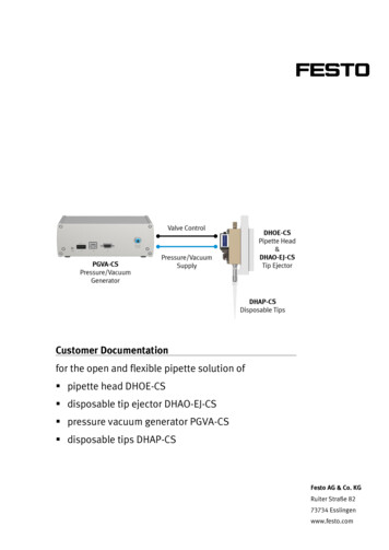
Customer Documentationfor the open and flexible pipette solution of pipette head DHOE-CS disposable tip ejector DHAO-EJ-CS pressure vacuum generator PGVA-CS disposable tips DHAP-CSFesto AG & Co. KGRuiter Straße 8273734 Esslingenwww.festo.com
Table of content1IMPORTANT NOTES . 41.1 INTENDED USE . 41.2 FORESEEABLE MISSUSE . 41.3 USABLE MEDIAS . 41.4 SAFETY INSTRUCTIONS . 41.5 QUALIFIED EXPERTS . 41.6 RETURN TO FESTO . 51.7 SERVICE. 52OVERVIEW. 63PRESSURE AND VACUUM GENERATOR PGVA-CS . 73.1 FUNCTION . 73.2 SPECIFICATIONS. 73.3 DIMENSIONS. 83.4 PERFORMANCE . 83.5 INTERFACES . 93.5.1Front connectors .93.5.2Power connector pinning .93.5.3LED status .93.6 COMMUNICATIONS . 103.6.1Serial connection.103.6.2Ethernet connection .103.7 CONTROLS . 133.7.1GUI (Graphical User Interface) .133.7.2ModbusTCP .153.8 CONFIGURATIONS . 183.9 ACCESSORIES. 184PIPETTE HEAD DHOE-CS . 194.1 FUNCTION . 194.2 SPECIFICATIONS. 194.2.1Dimensions .194.3 PERFORMANCE . 20DHOE customer documentationversion 1.0 (02.2022)Seite 2 von 28
4.4 INTERFACES . 204.5 CONFIGURATIONS . 204.6 ACCESSORIES. 215DISPOSABLE TIP EJECTOR DHAO-EJ-CS . 225.1 FUNCTION . 225.2 SPECIFICATIONS. 235.3 MATERIALS . 235.4 DIMENSIONS. 235.5 CONFIGURATIONS . 235.6 ACCESSORIES. 245.7 ASSEMBLY . 246DISPOSABLE TIPS DHAP-CS . 266.1 FUNCTIONS. 266.2 SPECIFICATIONS. 266.3 BIO BURDEN . 266.4 MATERIALS . 276.5 DIMENSIONS. 276.6 CONFIGURATIONS . 276.7 ACCESSORIES. 286.8 LIMITATION OF LIABILITY . 28DHOE customer documentationversion 1.0 (02.2022)Seite 3 von 28
11.1Important notesIntended useThe open and flexible pipette solution contains the PGVA-CS pressure/vacuum generator, DHOE-CS pipette head,DHAO-EJ-CS tip ejector and DHAP-CS disposable tips. The general-purpose is liquid transportation in laboratoryresearch or laboratory automation.The pipette solution is for dispensing and aspirating liquids according to the technical specifications and within thetechnical limits. Any different usage of the pipette solution is in the sole responsibility of the user.1.2Foreseeable missuseThe pipette solution is not approved for direct contact with foods.1.3Usable medias Media may escape in case of leakage. Provide protective measures when handling the product Use only compatible medias to which the materials of the product are resistant Use only medias that won’t cause dangerous reactions if mixed1.4Safety instructions Only use the product in original status without unauthorized modifications Only use the product if it runs in technical condition according the specification Do not exceed the maximum permissible pressure of the medium andtake pressure peaks inside the system into account Do not operate the product in the vicinity of easily flammable liquids and materials Supply the unit with an electronic power source that complies with the requirementsof an energy-limited circuit according to IEC 61010-1/EN 61010-1 Before working on the product, switch off the power supply and pressure/vacuum supplyand secure it against being switched on again1.5Qualified expertsWork on the product should only be conducted by qualified experts, who are familiar with the installation ofelectrical and fluid systems.DHOE customer documentationversion 1.0 (02.2022)Seite 4 von 28
1.6Return to FestoHazardous substances can endanger the health and safety of people and cause damage to the environment. Toprevent hazards, the product should only be returned if explicitly requested by Festo. Consult your regional Festo sales contact Complete the declaration of contamination and attach it to the documentation Comply with all legal requirements for the handling of hazardous substancesand the transport of dangerous goods1.7ServiceIn case of any questions, please check all information on Festo support portal www.festo.com/spor get in contact with your regional Festo sales support.DHOE customer documentationversion 1.0 (02.2022)Seite 5 von 28
2OverviewThe pipette solution is very open, easy to configure and extreme flexible. The main purpose is liquid transportation,e.g. for sample preparation. The pressure-driven pipette head DHOE-CS is supplied by the pressure/vacuumgenerator PGVA-CS and compatible with all sizes of the disposable tips DHAP-CS, which are highly resistant againstaggressive or chemical medias. After finishing the pipetting process, the disposable tip ejector DHAO-EJ-CSremoves the disposable tips DHAP-CS from the pipette head DHOE-CS.The pipette solution can handle different liquids in a wide range of volumes in high precision.DHOE customer documentationversion 1.0 (02.2022)Seite 6 von 28
3Pressure and vacuum generator PGVA-CSThe decentralized pressure and vacuum generator PGVA-CS only requires a 24 V power supply to providecompressed air for a pressure or vacuum-driven solution. The performance of pressure and flow fits perfect inliquid handling solutions for dispensing, aspirating and pipetting to supply the dispense and pipette heads fromFesto.3.1FunctionThe pressure and vacuum are generated in a high precise closed loop control with integrated gas pump,proportional piezo valve, pressure sensors and buffer reservoir. The filtered output pure air. The communicationinterface provides an easy control by GUI tool or PLC controller.3.2SpecificationsPneumatic control-500 500 mbarControl accuracy /- 5 mbarFlow rangeup to 1 l/minAir filter0,01 µmPneumatic interface4 mm (QS-4 fitting)Power supply24 VCommunication interfaceConfigurationDHOE customer documentationRS232 serial port for ASCIIRJ45 ethernet port for Modbus TCPGUI tool is available (download from SupportPortal)version 1.0 (02.2022)Seite 7 von 28
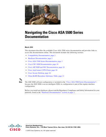
3.3Dimensions3.4PerformanceThe chart shows different flow rates of pressure levels from 50 450 mbar (max. pressure supply 500 mbar):The chart shows different flow rates of vacuum levels from -50 -450 mbar (max. vacuum supply -500 mbar):DHOE customer documentationversion 1.0 (02.2022)Seite 8 von 28
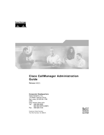
3.5Interfaces3.5.1 Front connectorsAStatus LightBPower Connector / Digital OutputCEthernet Connector RJ45DModbus ASCII Connector RS232EPneumatic Connector QS43.5.2 Power connector pinningPin 1 24 V DCPin 2 GNDPin 3 FEPin 4 OutputPin 5 GND3.5.3 LED statusLED greenLED redDHOE customer documentationModeDescriptionOffNo power supplyRunningUnit operates wellFunction errorInsufficient level in the pressure or vacuumchamber (level is below the defined threshold)Function errorLow pressure/vacuum level persistsBootloaderUnit is in bootloader modeUpdateFirmware update is in progress (via RS232)UpdateFirmware update is in progress (via Ethernet)version 1.0 (02.2022)Seite 9 von 28
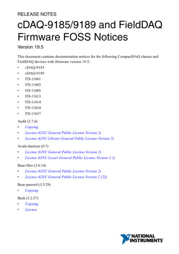
3.6CommunicationsThere are two ways to establish the communication with the PGVA by the GUI – via serial bus using RS232connection or via Ethernet-IP using the RJ45 connection.3.6.1 Serial connectionConnect the PGVA via 9-pin Sub-D connector for RS232 serial bus connection. Connect the cable, e.g. via RS232 toUSB connector, with your PC. Select the COM port [ 1 ] in the GUI to establish the connection by serial buscommunication. The baud rate is 115200 bps with 8 data bits and 1 stop bit.Refresh the COM ports by Botton [ 3 ] when the serial cable is pluggedinto the PC after the GUI was started3.6.2 Ethernet connectionConnect the PGVA via RJ45 Ethernet cable with the Ethernet port of a network switch or directly to your PC. Enterthe IP address [ 2 ] of the PGVA to establish the Ethernet IP connection. The default address is 192.168.10.102 withport 8502. Dynamic IP address setting by DHCP server is also possible.In case the connection will be made over Ethernet-IP, please consider that the PC must be on thesame network as the PGVA. The ethernet cable must be plugged in before starting the PGVA.If the ethernet cable is plugged in after the PGVA has started, the ethernet connection will not bepossible and a restart of the PGVA by disconnecting the power plug is necessary.Until the connection hasn’t been established successfully, many elements of the GUI will remain in gray.DHOE customer documentationversion 1.0 (02.2022)Seite 10 von 28
How to setup the Ethernet IP address on your PC into the same network as PGVA?1) Find the network connection in your task bar in the right corner and open it with the right mouse botton2) Open the “network setup”3) On the left side, choose “Ethernet”. Start “change adapter options” in “related settings”4) Choose the Ethernet port from your PC, which is connected to the PGVA. (Find the correct port by reconnectingthe RJ45 cable from on your PC). Open the menu with the right mouse botton and choose “seetings”.DHOE customer documentationversion 1.0 (02.2022)Seite 11 von 28
5) Choose the “internet protocol version 4 (TCP/IPv4)” and open the “settings”6) Change to manual setup of the IP address. The first three numbers have to be in the same range as the PGVA,like “192.168.10” in case of using the default IP address. The last number have to be different and unique inyour network, like the house number in a street. The Subnet-mask can be adjusted to the standard range of“255.255.255.0”. Confirm your setup with “OK”In case of individual adjustments of the IP address: the IP address should not start with 0.x.x.x, 127.x.x.x and have a value below 240.x.x.x. the MAC address should be in Festo range (00:0E:F0:00:00:00 to 00:0E:F0:FF:FF:FF). the last device-specific digits in the IP address should be in the range x.x.x.1 2477) Close your ethernet setup also with “OK”Now your PC works in the same network environment like the PGVA and the connection should establish.DHOE customer documentationversion 1.0 (02.2022)Seite 12 von 28
3.7Controls3.7.1 GUI (Graphical User Interface)[4] Chamber panelIn the "Desired" input box the user enters the positive pressure or negative vacuumin millibars for the maximum chamber supply and confirms the values by the "Set" button. The individual pressure range is between 200 1000 mbar The individual vacuum range is between -160 -640 mbarThe pump stops supplying the pressure and vacuum chamberswhen the desired value is reached (note the hysteresis). The pump starts supplying the pressure chamber if thepressure inside falls -100 mbar below “Desired” level The pump starts supplying the vacuum chamber if thevacuum inside falls 40 mbar above “Desired” levelThe “Actual” output box displays the pressure or vacuum levelfor the selected chamber which is currently reached.DHOE customer documentationversion 1.0 (02.2022)Seite 13 von 28
[5] Output pressure panelIn the "Desired" input box the user enters the positive pressure or negative vacuumin millibars for the supply of the liquid head and confirms the values by the "Set" button. The requested value controls the internal proportional valve to adjust the pneumatic output The pressure and vacuum range for the pneumatic output is between -500 500 mbarThe “Actual” output box displays the pressure or vacuum levelfor the pneumatic output which is currently reached.The additional output trigger actuation can either be used as an opening timedependent actuation or as a manual on / off switch using the digital outputfrom the PGVA connected with the liquid head for pipetting or dispensing.[ 6] Dispense and aspirate panelIn the “Dispense panel” the user enters in the "Pressure" input-boxthe desired pressure level between 0 500 mbar.In the “Aspirate panel” the user enters in the "Pressure" input-boxthe desired vacuum level between 0 -500 mbar.In the "Time" input-box the user enters the opening time of the valvefrom the liquid head in milliseconds. For this duration, the digital outputof the PGVA will be activated (switching times from valves are not considered).In the "Cycles"input-box user enters the number of cycles for which the operationshould be repeated, e.g. in case of multidispensing.After activating the "Dispense"or "Aspirate" buttons, the following actions are taken: Control of the "Desired" pressure Activate digital output for the adjusted "Time" Repeat actions for requested numbers of "Cycles”DHOE customer documentationversion 1.0 (02.2022)Seite 14 von 28
[ 7 ] Communication statusDisplays whether the last Modbus command was successful or not.[ 8} Change IP addressIn the "Static IP" input-box user changes the IP address manually, whichis needed to integrate the PGVA into the existing network environment.With the "Set" button the IP address will be persistently stored on the deviceand the user will be notified to reset the device and reconnect with the new setting.3.7.2 ModbusTCPRegister nameand addressTypeOffsetScalingAction when readAction when writtenVacuum actualADDR: 0x100Input registerDimension: mbar-1498.334 1.332Acquires actual pressure in thevacuum tank and returns it asModbus slave FC04 replyN/APressure actualADDR: 0x101Input registerDimension: mbar-1498.334 1.332Acquire actual pressure in thepressure tankN/AOutput pressureactualADDR: 0x102Input registerDimension: mbar-5000.244Acquire actual pressure andvacuum box output pressureN/APGVA status wordADDR: 0x106Input registerBitfield. Pleaserefer to Table 1.below.01Reads the status of the PGVAN/A01Reads the most-significanthalfword of the 32-bit counter forthe total number of dispense valveopenings.N/A01Reads the least-significanthalfword of the 32-bit counter forthe total number of dispense valveopeningsN/ADispense valveopening times(MSH):ADDR: 0x107Dispense valveopening times(LSH):ADDR: 0x108Input registerDimension: Upper16 bits of a 32-bitintegerInput registerDimension: Lower16 bits of a 32-bitintegerVacuum actual (inmbar)ADDR: 0x10DInput registerDimension: mbar01Same reading as register 0x100,however, the conversion betweenincrements and millibar is done inthe firmware.Pressure actual (inmbar)ADDR: 0x10EInput registerDimension: mbar01Same reading as register 0x101,however, the conversion betweenincrements and millibar is done inthe firmware.Output pressureactual (in mbar)ADDR: 0x10FInput registerDimension: mbar1Same reading as register 0x102,however, the conversion betweenincrements and millibar is done inthe firmware.Valve actuationtimeADDR: 0x1000Holding registerDimension: msDHOE customer documentation001Reading this register will alwaysreturn: 0xFFFF.version 1.0 (02.2022)Actuate output electromagneticvalve with a period matching valueto write in Modbus frameNote: output electromagnetic valveis an option for the product - itmight be installed on devices usedto demonstrationsSeite 15 von 28
Vacuum threshold*ADDR: 0x1001(lowest pressureat which vacuumHolding registerpump isDimension: mbardeactivated afterregulating vacuumtank pressure)Pressurethreshold*ADDR: 0x1002(highest pressureat which air pumpis deactivatedafter filling uppressure tank)Holding registerDimension: mbarWhenwriting:1124.5Whenreading: 1498.334Whenwriting:1124.5Whenreading: ting:0.7505Whenreading:1.332Returns vacuum thresholdSets vacuum threshold.Note: the SW implementshysteresis in vacuum regulator the value from Modbus command isapplied immediately but, in somecases, if the change is in lower thanhysteresis the device will react atthe moment pressure reached thevacuum thresholdReturns pressure thresholdSets pressure threshold.Note: the SW implementshysteresis in pressure regulator the value from Modbus command isapplied immediately but, in somecases, if the change is in lower thanhysteresis the device will react atthe moment pressure reached thethresholdHolding registerDimension: mbarWhenwriting:2047.5Whenreading: 500Whenwriting:4.095Whenreading:0.244Returns output pressure set pointvalueSets output pressure set pointvalue.Note: The set point value is appliedfor less than 2.5ms after theModbus command is received.However, the output pressureregulator will need some time toregulate the output value. This timedepends on the difference betweennew and old set point values, theoutput flow rate and howfull/empty are pressure tank andvacuum tankModbus TCPPort**ADDR: 0x100CHolding registerDimension: LSB01Reads the TCP port for ModbuscommunicationSets the TCP port for Modbuscommunication.Modbus unit IDADDR: 0x100DHolding registerDimension: LSB01Read the Modbus unit ID of thePGVASets the Modbus unit ID of thePGVA1Reading the register is the same asregister 0x1001, however,conversion between incrementsand millibars is done in thefirmware.Writing to this register has thesame effect as writing to register0x1001, however, value written willbe interpreted as millibars insteadof increments.1Reading the register is the same asregister 0x1002, however,conversion between incrementsand millibars is done in thefirmware.Writing to this register has thesame effect as writing to register0x1002, however, value written willbe interpreted as millibars insteadof increments.Writing to this register has thesame effect as writing to register0x1003, however, value written willbe interpreted as millibars insteadof increments.Output pressureADDR: 0x1003(output pressureset point value)Vacuum threshold(in mbar) *ADDR: 0x100E(lowest pressureat which vacuumpump isdeactivated afterregulating vacuumtank pressure)Holding registerDimension: mbarPressure threshold(in mbar) *ADDR: 0x100F(highest pressureHolding registerat which air pump Dimension: mbaris deactivatedafter filling uppressure tank)00Output pressure(in mbar)ADDR: 0x1010(output pressureset point value)Holding registerDimension: mbar01Reading the register is the same asregister 0x1003, however,conversion between incrementsand millibars is done in thefirmware.Manual triggerADDR: 0x1011Holding registerDimension: 0 or 101Reads the current state of theoutput.Writing 1 to this register opens theoutput valve, 0 – closes itIP Address(MSH)**, ***ADDR: 0x3000Multiple registersDimension: LSB01Read the most-significant 16-bits ifthe PGVA static IP addressSet the most-significant 16-bits ifthe PGVA static IP address.Multiple registersDimension: LSB01Read the least-significant 16-bits ifthe PGVA static IP addressSet the least -significant 16-bits ifthe PGVA static IP address.GW Address(MSH)**, ***ADDR: 0x3002Multiple registersDimension: LSB01Read the most-significant 16-bits ifthe PGVA static gateway addressSet the most-significant 16-bits ifthe PGVA static gateway address.GW AddressMultiple registers01Read the least-significant 16-bits ifSet the least -significant 16-bits ifIP Address (LSH)**,***ADDR: 0x3001DHOE customer documentationversion 1.0 (02.2022)Seite 16 von 28
(LSH)**, ***ADDR: 0x3003Netmask (MSH)**,Dimension: LSBthe PGVA static gateway addressthe PGVA static gateway address.Multiple registersDimension: LSB01Read the most-significant 16-bits ifthe PGVA static netmaskSet the most-significant 16-bits ifthe PGVA static netmask.Netmask (LSH)**, *** Multiple registersADDR: 0x3005Dimension: LSB01Read the least-significant 16-bits ifthe PGVA static netmaskSet the least -significant 16-bits ifthe PGVA static netmask.***ADDR: 0x3004* Register value can be stored persistently to the EEPROM with by writing to “Store to EEPROM” register.** To have an effect, register value must be stored to the EEPROM, wait for 1 second and perform a power reset.*** Register values must be written at once only with function code 0x10 (Write multiple registers). For example,write multiple registers(0x3006, [0xAAAA, 0xBBBB, 0xCCCC]). In case register value does not match the numbersize of parameter represented by the register (for example, write multiple registers(0x3006, [0xAAAA, 0xBBBB])),a ILLEGAL DATA ADDRESS Modbus exception is returned.PGVA status wordBitsMeaning16:9Reserved80: No EEPROM write pending1: EEPROM write pending70: No overtemperature1: Overtemperature6:50: Supply voltage is nominal1: Supply voltage low2: Supply voltage high40: Vacuum in the vacuum tank is nominal1: Vacuum in the vacuum tank is above than the higher threshold30: Pressure in the pressure tank is nominal1: Pressure in the pressure tank is below the lower threshold2:10: Pump is off1: Pump is building up pressure2: Pump is building up vacuum3: Reserved00: Idle1: BusyDHOE customer documentationversion 1.0 (02.2022)Seite 17 von 28
3.8ConfigurationsPart numberType code and product description8146318PGVA-CS pressure / vacuum generator 1-channel3.9AccessoriesPart numberType code and product description8106756NECC-L8G5-C1 5-pin terminal strip8145992SLFH-033-NS-CS hydrophobic filter unit8145991LUER-M-3/32-CS barbed adapterAll accessories are included once in the main component and can be ordered as spare parts on request.The usage of the hydrophobic filter is mandatory to prevent contaminationinside the device from the evaporation of the liquids.DHOE customer documentationversion 1.0 (02.2022)Seite 18 von 28
4Pipette head DHOE-CS4.1FunctionThe pipette head DHOE-CS can control vacuum for aspiration and pressure for dispensing. The integrated mediaseparated switching valve just needs a power supply of 24 V. Depending on the actuation time (resp. opening time)of the valve, the requested volume can be adjusted very flexible. All wetted materials of the pipette head DHOE-CSare compatible with liquids. In case of contamination or overaspiration, the pipette heat can be cleaned quiteeasily.4.2SpecificationsOperating pressure-0.2 to 0.65 barOperating voltage24 V DC ( /-10%)Power consumption2.0 WDuty cycle100%Medium temperature5 to 50 CAmbient temperature5 to 40 CIP protectionIP30Material complianceRoHSPWIS conformityVDMA24364-Zone IIICE certificationnot required4.2.1 DimensionsDimensions8,1 x 76,2 x 30 mmPitch9 mm (perfect fit for 96 microwell plate,also suitable for 384 and 1536 wells with gantry)DHOE customer documentationversion 1.0 (02.2022)Seite 19 von 28
4.3PerformancePipetting volume1 µl up to 10 ml (depending on maximum tip size)Pipetting throughputup to 3 ml/secPipette accuracyThe control of the DHOE pipette head is open loop. The behavior ofeach DHOE pipette head is different, depending on the setup andenvironment. So, the target volume needs individual adjustment ofpressure/vacuum level and valve opening time.The accuracy depends on the specific adjustment by the customer.Pipetting precision 5 % CV for volume below 5 µl 2 % CV for volume below 50 µl 1 % CV for volume below 500 µl 0.5 % CV for volume below 1000 µlThe precision of the open loop solution depends on static conditions ofthe setup and environment.Pipette setupindividual speed adjustabledifferent viscosities adjustableOptional pipetting featurespressure based liquid level detection(specific adjustments accordingmultidispensingindividual system design necessary)tip sensingtip acesPower connector2 pins with open leadsFluid connectionFemale thread UNF 1/4-28Mechanical Mounting2 screws M2 with H7 centering ring4.5ConfigurationsPart numberType code and product description8143216DHOE-1-1-A-T-CS single channel pipette head for high throughput8143217DHOE-1-1-A-P-CS single channel pipette head for high precisionDHOE customer documentationversion 1.0 (02.2022)Seite 20 von 28
4.6AccessoriesPart numberType code and product description8104286NLFA-D-U14-K3-PP-P10 liquid fitting for 3,0 mm tubingAll accessories are included once in the main component and can be ordered as spare parts on request.DHOE customer documentationversion 1.0 (02.2022)Seite 21 von 28
55.1Disposable Tip Ejector DHAO-EJ-CSFunctionThe disposable tip ejector DHAO-EJ-CS removes the disposable tips DHAP-CS in combination with the singlechannel pipette heads DHOE-CS. The mechanism works like a mechanical slide against a fix blockage actuated bythe z-axis from customers handling gantry. Therefore, no additional electrical connection on the front end isnecessary.Notes The contact area on the mounting plate must be flat (flatness tolerance 0.05 mm) The stopper shall cover the whole contact surface of the sliding piece The max. force acting on the sliding piece must be limited to 35 N The force acting on the tip adapter must be limited to 30 N Open loop pipette, ejector, mounting plate and stopper must be well aligned When a torque is applied on the tip adapter (replacement of tip adaper e.g.), the manifold of the liquid frontend needs to be supported/held in order to avoid an overloading of the screws and threads.DHOE customer documentationversion 1.0 (02.2022)Seite 22 von 28
5.2SpecificationsEjection forceup to 35 NSliding stroke10 mmMounting ThreadM3 x 4 mmAmbient temperature5 . 40 CStorage temperature20 . 70 CRelative air humidity0 . 95 % (no condensation)Corrosion resistance classCRC 0PWIS conformityVDMA24364-Zone III5.3MaterialsSliding pieceWhite POMMounting pieceAluminum 6061 T651 (anodized)Return springStainless steel5.4DimensionsDimensions7,8 x 85 x 18 mmPitch9 mm5.5ConfigurationsPart numberType code and product description8150866DHOA-EJ-1-1-V1-CS Disposable Tip EjectorDHOE customer documentationversion 1.0 (02.2022)Seite 23 von 28
5.6AccessoriesPart numberType code and product description189652ZBH-5 centering ring---M2 x 20 mm mounting screw for DHOE-CS(torque max. 0,1 -10% Nm)8140774EHAM-MA-E19-25-C11 adapter plate(choose from Festo catalogue)EGSC or EGSK axis---M2 x 24 mm mounting screw for DHOE-CS and EHAM(torque max. 0,1 -10% Nm)The
3.6.2 Ethernet connection Connect the PGVA via RJ45 Ethernet cable with the Ethernet port of a network switch or directly to your PC. Enter the IP address [ 2 ] of the PGVA to establish the Ethernet IP connection. The default address is 192.168.10.102 with port 8502. Dynamic IP address setting by DHCP server is also possible.