Transcription
This article has been accepted for inclusion in a future issue of this journal. Content is final as presented, with the exception of pagination.IEEE TRANSACTIONS ON ROBOTICS1Modeling of Soft Fiber-ReinforcedBending ActuatorsPanagiotis Polygerinos, Member, IEEE, Zheng Wang, Member, IEEE, Johannes T. B. Overvelde, Kevin C. Galloway,Robert J. Wood, Katia Bertoldi, and Conor J. Walsh, Member, IEEEAbstract—Soft fluidic actuators consisting of elastomeric matrices with embedded flexible materials are of particular interestto the robotics community because they are affordable and canbe easily customized to a given application. However, the significant potential of such actuators is currently limited as their designhas typically been based on intuition. In this paper, the principleof operation of these actuators is comprehensively analyzed anddescribed through experimentally validated quasi-static analyticaland finite-element method models for bending in free space andforce generation when in contact with an object. This study provides a set of systematic design rules to help the robotics communitycreate soft actuators by understanding how these vary their outputs as a function of input pressure for a number of geometricalparameters. Additionally, the proposed analytical model is implemented in a controller demonstrating its ability to convert pressureinformation to bending angle in real time. Such an understandingof soft multimaterial actuators will allow future design conceptsto be rapidly iterated and their performance predicted, thus enabling new and innovative applications that produce more complexmotions to be explored.Index Terms—Bending, fiber reinforced, fluidic actuator, modeling, soft robot.I. INTRODUCTIONOFT robotics is a rapidly growing research field that combines robotics and materials chemistry, with the ability topreprogram complex motions into flexible elastomeric materials(Young’s modulus 102 106 Pa) [1]–[4]. These soft systemsare engineered using low-cost fabrication techniques, provideadaptable morphology in response to environmental changes,and are ideally suited for gripping and manipulating delicateobjects [2]–[7].SManuscript received March 26, 2014; revised February 1, 2015; acceptedApril 23, 2015. This paper was recommended for publication by AssociateEditor S. Hirai and Editor B. J. Nelson upon evaluation of the reviewers’ comments. This work was supported in part by the National Science Foundationunder Grant #1317744 and Grant #IIS-1226075, by DARPA Award W911NF11-1-0094, and by the Wyss Institute and the School of Engineering and AppliedSciences, Harvard University.P. Polygerinos, R. J. Wood, and C. J. Walsh are with the School of Applied Sciences and Engineering and Wyss Institute, Harvard University, Cambridge, MA 02138 USA (e-mail: polygerinos@seas.harvard.edu; rjwood@seas.harvard.edu; walsh@seas.harvard.edu).Z. Wang is with the Department of Mechanical Engineering, The Universityof Hong Kong, Hong Kong (e-mail: zwangski@hku.hk).J. T. B. Overvelde and K. Bertoldi are with the School of Applied Sciences and Engineering and Kavli Institute for Bionano Science and Technology, Harvard University, Cambridge, MA 02138 USA (e-mail: overvelde@seas.harvard.edu; bertoldi@seas.harvard.edu).K. C. Galloway is with Wyss Institute, Harvard University, Cambridge, MA02138 USA (e-mail: kevin.galloway@wyss.harvard.edu).Color versions of one or more of the figures in this paper are available onlineat http://ieeexplore.ieee.org.Digital Object Identifier 10.1109/TRO.2015.2428504Soft actuators are commonly constructed as monolithic structures from compliant materials such as electroactive polymers[8]–[10], shape memory alloys [11], [12], elastomers [2], hydrogels [13], [14], or composites that undergo a solid-state phasetransition [15]. Their actuation can be achieved by a varietyof stimuli, including electrical charges [9]–[12], chemical reactions [16], [17], and pressurized fluids [2], [3], [7], [15]–[22]. Inparticular, pneumatic and hydraulic powered soft actuators arepromising candidates for robotics applications because of theirlightweight, high power-to-weight ratio, low material cost, andease of fabrication with emerging digital fabrication techniques[15]–[19], [23]. Upon pressurization, embedded chambers inthe soft actuator expand in the directions associated with lowstiffness and give rise to bending [2], twisting [24], and extending/contracting motions [25]. Furthermore, these actuators canbe integrated into the structure of soft robotic systems both asactuators and structural elements [2], [3], [5], [7], [18], [25],[26]. For a more comprehensive view on the soft robotic literature, the authors refer to review works of Majidi [1], Trivediet al. [27], and Kim et al. [28].While empirical approaches have highlighted the excitingpotential of soft actuators, the lack of robust models for softmultimaterial fluidic actuators is greatly limiting their potential.Predicting a soft actuator’s performance (e.g., deformation andforce output in response to a pressurized fluid) prior to manufacture is nontrivial due to the nonlinear response and complexgeometry. One class of soft actuators that has received significant research attention in recent years are soft bending actuators,but limited modeling work has been conducted. To make theseactuators widely applicable, a systematic understanding of therelationship between actuator geometry and its performance isrequired.In this study, soft actuators are considered that are activatedby pressurized air and are constructed from a combination ofelastomeric (hyperelastic silicones) and inextensible materials(fabrics and fibers), i.e., soft fiber-reinforced bending actuators(see Fig. 1) [8], [29]–[31]. Compared with existing geometrically complex soft bending actuator designs with bellows [2],[3], [18], [24], the widely used soft fiber-reinforced bending actuators have a much simpler tubular geometry that offers easeof manufacture, and where fibers can be arranged along theirlength to enable nontrivial deformation modes. In addition, astrain-limiting layer added to one side enables bending. To getdeeper insight into the response of the system and be able to efficiently design application-specific soft actuators, quasi-staticanalytical and finite-element method (FEM) models are developed. Compared with previous FEM models, the proposed 3-Dmodels capture the contact interaction information between the1552-3098 2015 IEEE. Personal use is permitted, but republication/redistribution requires IEEE permission.See http://www.ieee.org/publications standards/publications/rights/index.html for more information.
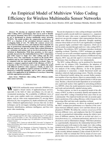
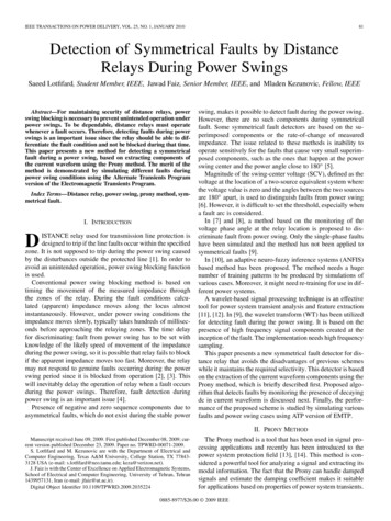
This article has been accepted for inclusion in a future issue of this journal. Content is final as presented, with the exception of pagination.2IEEE TRANSACTIONS ON ROBOTICSFig. 1. (a) Soft fiber-reinforced bending actuator in the unpressurized stateand a closeup view of the fiber reinforcements (fiber winding). (b) Same actuatorin the pressurized state.straining elastomer material and the nonstraining fiber reinforcements. This enables to capture in a realistic manner thebehavior of the bending actuators while providing details aboutstress concentration points and the generated strains. In addition, a series of experimental tests are conducted to validatethe models. In particular, 1) the bending of the actuator in freespace and 2) the force applied by the actuator at its proximaltip when in contact with an object are measured. Furthermore,the developed analytical model is used in feedback control loopexperiments to demonstrate its ability to perform real-time conversion of the supplied air pressure signal into bending angleinformation.II. ACTUATOR FABRICATIONThe widely used design of the soft fiber-reinforced bendingactuator is in this study fabricated following a new multistepmolding process developed by the authors that ensures fasterproduction times and more robust and repeatable actuator outcomes. This fabrication technique is comprised of four parts:1) a hemicircle elastomeric air chamber (including the caps atthe distal and proximal ends); 2) circumferential fiber windingsthat run along the length of the chamber; 3) an inextensiblebase layer; and 4) a soft coating material (sheath) that encapsulates the entire system [31]. The circumferential reinforcementprovided by the fibers limits radial expansion and promoteslinear extension, while the strain limiting layer at the base restricts linear extension on one face of the actuator. Therefore, asthe actuator is pressurized, part of it expands while the strainlimited portion restrains any linear expansion along one surface(see Fig. 1), producing a bending motion. More details aboutthe described fabrication method can also be found at the softroboticstoolkit.com website [38] The Soft Robotics Toolkit is acollection of shared resources to support the design, fabrication,modeling, characterization, and control of soft robotic devices.To offer complete control over every aspect of the assembledactuator including geometry, material properties, and pattern offiber reinforcements, a multistep molding approach was used.The molds for the actuator were 3-D printed with an ObjetConnex 500 printer. The first rubber layer (Elastosil M4601A/B Wacker Chemie AG, Germany) [see Fig. 2(a)] used a halfround steel rod to define the interior hollow portion of the actuator. Woven fiberglass (S2-6522, USComposites, FL, USA)was glued to the flat face to serve as the strain limiting layer[see Fig. 2(b)]. After molding the first rubber layer, fiber reinforcements were added to the surface [see Fig. 2(c)]. A singleKevlar fiber (0.38-mm diameter) was wound in a double helixpattern around the length of the actuator body. Raised featuresin the mold were transferred to the actuator surface to definethe fiber path for consistency of fiber placement. Fiber reinforcements were further secured by placing the entire assemblyinto another mold to encapsulate the actuator body in a 1.0-mmthick silicone layer (Ecoflex-0030 silicone, Smooth-on Inc., PA,USA) [see Fig. 2(d)]. The actuator body was then removed fromthe mold and the half round steel rod [see Fig. 2(e)]. The firstopen end was capped by placing it into a small cup of uncuredsilicone. Once this end cured, a vented screw was fed throughthe 15-mm-thick silicone cap to form the mechanical connection for the pneumatic tubes (see Fig. 2(e), top right). The otheropen end was capped in a similar manner (see Fig. 2(e), lowerright).III. ACTUATOR MODELINGIn rigid-bodied robots, there are well-defined models to characterize the motion of mechanical linkages and the force theycan produce. In this study, both detailed FEM models andcomputationally inexpensive analytical models of a soft fiberreinforced bending actuator were pursued to analyze the behavior of the actuator and obtain a relationship between the inputair pressure and the bending angle, as well as the relationshipbetween the input air and the output force.A. Analysis of Actuator Cross-Sectional ShapesThe actuator design can be tuned by varying a number ofgeometrical parameters including the wall thickness of the airchamber, the length of the actuator, the diameter of the hemicircle chamber shape, and the fiber winding pitch and orientation(see Fig. 3). Changing any of these parameters will result indifferent performance. Furthermore, the shape of the cross section can also significantly affect the response of the system asthe magnitude of the area determines the force generated by thepressure acting on it and it will also influence the stress distribution in the elastic material as it resists expansion. In the past,rectangular (RT), circular (FC), and hemicircular (HC) shapeshave been used in soft actuator designs without explicitly comparing their efficiencies [8], [29], [32]. In this study, these threecross-sectional shapes were compared to identify the most effective shape for a soft bending actuator based on which requiresthe least pressure to bend to the same angle while preserving itsoriginal cross-sectional shape.
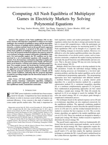
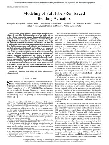
This article has been accepted for inclusion in a future issue of this journal. Content is final as presented, with the exception of pagination.POLYGERINOS et al.: MODELING OF SOFT FIBER-REINFORCED BENDING ACTUATORS3Fig. 2. Schematic outlining some stages of the soft fiber-reinforced bending actuator fabrication process. (a) First molding step using a 3-D printed part.(b) Strain limiting layer (woven fiberglass) is attached to the flat face of the actuator. (c) Thread (Kevlar fiber) is then wound along the entire length of the actuator.(d) Second molding step: the entire actuator is encapsulated in a layer of silicone to anchor all fiber reinforcements. (e) In the final step, the half-round steel rod isremoved and both ends of the actuator are capped allowing one end to have a port for the inflow/outflow of air.Fig. 3. Soft fiber-reinforced bending actuator showing numbered and labeled the geometrical parameters and design variables that can affect its behavior.Materials A, B, C, and D represent the material properties of the actuator body, sheath, fiber reinforcements, and base inextensible layer, respectively.The dimensions for each shape were obtained [see Fig. 4(a)]using the same cross-sectional area of a2 , and v is the ratiobetween rectangular edges. Assuming an actuator wall thickness of t a/4, with an input air pressure of Pin , the bendingtorques(Ma ) of internal air pressure against the distal cap of theactuator geometry were calculated as0.5 3a Pinv(1)MaHC 0.34a3 Pin(2)MaFC(3)MaRT 3 0.72a Pin .A larger Ma value indicated that a particular shape could generate a larger bending torque for the same input pressure.To create actuator bending, the torque Ma must overcome theinternal bending moments, which are also functions of the actuator geometry. To quantify and compare this effect, the ratio of theactuator internal bending moment and the pressure-generatedbending torque Ma is denoted as the bending resistance, and thebending resistance for all three cross-sectional shapes is shownin Fig. 4(b) for a bending angle ranged from 0 to 360 . Alower vertical axis value indicates an actuator that is theoretically easier to bend, and therefore, the RT shape was foundless suitable since it required the highest amount of pressure toreach the same bending angle. On the other hand, the HC wasfound easier to bend. Additionally, the RT shape was assumedwith a ratio (v) of 1.47, such that it could generate a bendingtorque Ma equal to that of the HC shape when the same amountof pressure Pin was provided. As a result, both the RT and FCshapes demonstrated similar bending resistance. Based on theabove, the HC shape was chosen for this study.B. Analytical ModelingAn analytical model was developed that captures the explicitrelationship between input pressure, bending angle, and outputforce by taking into consideration both the hyperelastic materialproperty of silicone rubber and the geometry of the actuator.The variables in the model were actual actuator dimensions andmaterial properties that could be either measured or obtainedfrom calibrations.
This article has been accepted for inclusion in a future issue of this journal. Content is final as presented, with the exception of pagination.4IEEE TRANSACTIONS ON ROBOTICSFig. 4. (a) Cross-sectional views of a rectangular (RT), hemicircle (HC), andfull circle (FC) actuator shape with equal cross-sectional area and with a strainlimiting layer attached at their bottom face. (b) Efficiency comparison (bendingresistance) of the different actuator shapes. A lower bending resistance indicatesthat an actuator is easier to bend with less pressure.Fig. 5. (Top left) Side view of the soft fiber-reinforced bending actuator ina bending state. Closeup view: view of the actuator distal tip showing thegenerated moments. Lower center: Cross-sectional view of the actuator.that1) Material Model: The soft fiber-reinforced bending actuators were fabricated using silicone rubber. This was modeled asan incompressible Neo–Hookean (NH) material [33] so that thestrain energy is given byW μ(I1 3)2(4)where I1 is the first invariant of the three (axial, circumferentialand radial) principal stretch ratios λ1 , λ2 , and λ3 asI1 λ21 λ22 λ23(5)λ1 λ, λ2 1, λ3 (6)2) Model for Bending Angle in Free Space: A geometricalmodel of the soft fiber-reinforced bending actuator that relatesthe input air pressure and the bending angle in free space isderived fully accounting for large deformations. It was assumedthat when compressed air (P1 Patm ) is supplied to the airchamber, the top wall will extend while the bottom layer will beconstrained by the inextensible layer, thus causing the actuatorto bend toward the bottom layer with a radius R and angle θ (seeFig. 5). Here, the fiber-reinforced mechanism was considered tobe a hard constraint to the actuator. Although the actuator hasa multilayered structure, for the sake of simplicity, it was modeled as a homogeneous incompressible NH material [33] witheffective initial shear modulus μ̄. The dynamics associated withpressurization were neglected in the model, and it was assumedthat the actuator always has a uniform bending curvature.Here, the principal stretch λ1 along the axial direction ofthe actuator was denoted. Furthermore, due to the fiber reinforcement constraint, the strain in the circumferential direction was negligible so that λ2 1. Finally, considering theincompressibility of the material, λ1 λ2 λ3 1, it was obtained(7)Next, a vanishing stress was assumed in radial directionthrough the thickness of the actuator (i.e., s3 0), and by combining (6) with (4) and (5) as WP1s1 μ̄ λ 3(8) λ1λ1λ WP1 μ̄ 1 2(9)s2 λ2λ2λP 0λ3μ̄p μ̄λ23 2 .λand μ is the initial shear modulus of the material. The principalnominal stresses si could then be obtained as a function of W ,λi , and the Lagrange multiplier p as Wp .si λiλi1.λs3 μ̄λ3 (10)(11)Within the range of stretches considered in this application(1 λ 1.5), the circumferential stress s2 was significantlysmaller than s1 (i.e., s2 s1 /2). Therefore, s1 was consideredto be the only nonvanishing principal stress and hereafter denoted as s.The internal stretch of the actuator materials resulted in anopposing bending moment. Therefore, at each bending configuration, a torque equilibrium was reached around the fulcrum O,as it is shown in Fig. 5, that can be obtained fromMa Mθ(12)where Ma is the bending torque of internal air pressure againstthe distal cap of the actuator, and Mθ is the combined momentof the stresses st and sb on the top and bottom layers. Using thehemicircular geometry with radius a the distal actuator cap wasa, Ma can be calculated as π2Ma 2 (P1 Patm )(a sin ϑ b) a2 cos2 ϑ dϑ03 24a 3πa b(P1 Patm ) .6(13)
This article has been accepted for inclusion in a future issue of this journal. Content is final as presented, with the exception of pagination.POLYGERINOS et al.: MODELING OF SOFT FIBER-REINFORCED BENDING ACTUATORSMoreover, combining the effect of the stresses acting on thetop and bottom layers, the bending moment is bsβ · 2 (a t) LβdβMθ 0 t 20π2 2sτ ,φ (a τ ) sin φ b (a τ ) Ldφ dτ.0(14)Furthermore, by introducing the local coordinate β, the longitudinal stretch and strain in the bottom layer can be calculatedas (see Fig. 5)L/θ ββθR β 1RL/θL 1sβ μ̄ λβ 3 .λβλβ (15)(16)Similarly, for the top layer with the coordinate τ (see Fig. 5):R b sinφ (a τ )R 1 μ̄ λτ ,φ 3.λτ ,φλτ ,φ (17)sτ ,φ(18)By substitution of (13) and (14) into (12), a relationship between the input air pressure Pin and the bending angle θ in freespace can be obtainedPin 6Mθ (θ)4a3 3πa2 b(19)where Pin P1 Patm , a and b are the air chamber radius andbottom thickness of the actuator, respectively, and Mθ (θ) wasgiven in (14). Substituting (15)–(18) into (14) to eliminate s andλ, it is possible to show that Mθ is a function of μ̄, a, b, t, andθ.However, the integral in (14) could not be computed analytically,and therefore (14), and hence (19), had to be solved numerically.The material property coefficient μ̄ can be obtained throughcalibration tests.3) Model for Bending Torque/Force: An expression for theactuator force can be derived by extending the analytical modelpreviously developed for bending angle. In this analysis, theactuator was assumed to be constrained at a zero bending angle(i.e., constrained in a flat configuration) such that no internalbending moments (Mθ ) were generated under pressurization.Therefore, the torque equilibrium at the fulcrum O of Fig. 5becomesMf F Lf Ma κPin(20)where F is the contact force between the actuator distal capand the environment, Lf is the distal cap length, Mf is theexternal bending torque generated by the contact force aroundO, combining (20) with (13), and κ is a function of the actuatorgeometry given byκ 4a3 3πa2 b.6(21)5This equation describes the pressure–force relationship underan isometric process (constant bending angle). Although (20) isonly applicable for a specific bending angle (i.e., zero degrees),it does provide insight into the relationship between actuatorgeometry and bending force. It also follows that under isotonicconditions (constant pressure), the force output will decrease asbending angle increases, because larger bending moments arerequired to bend the actuator to the desired angle. Hence, thebending force described in (20) can be defined as the maximumforce output for a particular input pressure.C. Finite-Element Method ModelingThe analytical model quickly generates insights into the response of an actuator to pressurized air for a particular geometry.However, it cannot capture certain aspects of the soft actuatorbehavior such as the interaction of internal layers of different materials. FEM models, on the other hand, provide a morerealistic description of the nonlinear response of the system, although at a higher computational cost. An additional advantageof FEM is that the deformation (and stress) in soft actuators canbe readily visualized, leading to a better understanding of theinfluence of local strain on global actuator performance. Priorwork on FEM modeling soft elastomeric actuators with fiberreinforcements has demonstrated the shape due to bending [7],[34], but minimal work has been done to validate these modelsexperimentally or used to characterize the actuator stiffness andforce-generating capabilities [35], [36].Prior to simulations, elastomeric samples of the individualmaterials used to fabricate the actuator were tested according to ASTM D638 (Type IV) at a rate of 500 mm/min foruniaxial tensile strength, and compression samples were compressed at a rate of 500 mm/min to obtain accurate materialproperties. A hyperelastic incompressible Yeoh material model[37], with strain energy U 2i 1 Ci (Ii 3), was used tocapture the nonlinear material behavior of both the Elastosiland the Ecoflex materials. In particular, the material coefficients were C1 0.11MPa, C2 0.02MPa for the Elastosiland C1 0.012662MPa and C2 0MPa for the Ecoflex. It isnoted that the initial shear modulus was μ̄ 2C1 .To model the behavior of the actuators, 3-D FEM modelswere constructed and analyzed with ABAQUS/Standard (Simulia, Dassault Systemes). Simplifications in the model were keptto a minimum in order to closely match the experimental setup.The inlet for pressurized air was not taken into account in themodel as the pressure was applied to all the internal walls ofthe chamber. All the components of the actuator were modeledusing solid tetrahedral quadratic hybrid elements (Abaqus element type C3D10H). For the thin fiber windings, quadratic beamelements were used (Abaqus element type B32), which wereconnected to the Elastosil by tie constraints. The material of thefiber winding was modeled as linear elastic (Young’s modulus ofE 31, 076MPa and a Poisson’s ratio of v 0.36). The number of nodes and elements used in the models are summarizedin Table I.As expected, the modeled beam elements introduced somebending support, while the fiber windings provided no bending
This article has been accepted for inclusion in a future issue of this journal. Content is final as presented, with the exception of pagination.6IEEE TRANSACTIONS ON ROBOTICSTABLE INUMBER OF NODES AND ELEMENTS FOR THE SOFT ACTUATOR FEM ngth(mm)Wall Thickness(mm)Number ofNodesNumber ofElements 02.02.01.02.03.02.02.071 30995 061118 70898 113128 78790 449160 711185 274192 650208 92144 46559 10873 61462 30181 21955 141101 097118 557121 106131 646stiffness. To decrease the modeled stiffness from the beam elements, the radius of the beam elements was reduced by a factorof 2. This radius reduction resulted in an insignificant changein tensile strength of the wire as it remained significantly stifferthan the elastomer. It is also noted that although the physicalfiber windings did not have any compressive stiffness, the beamelements of the FEM model added some. However, the influence of this effect on the simulation result can be neglected,since all the beams were under tension. Furthermore, for sakeof computational efficiency and to increase the convergence ofthe simulation, the bottom layer of the actuator, consisting of aninextensible layer, was modeled as an elastomer (Yeoh materialwith Ccombined 7.9MPa). The stiffness of the combined layerremained sufficient to function as an inextensible layer. Finally,to model loading of the actuator, an internal pressure was appliedto the surface of the chamber. The deformation of the actuatorobtained with the proposed FEM model is illustrated in Fig. 6.Similarly, the previously developed FEM model was also usedto conduct a force analysis. In this force model, the proximalcap was completely fixed, and the bending deformation of theactuator was also constrained. The force was then determinedby summing the reaction forces at the nodes on the edge of thedistal cap.Fig. 6. Three-dimensional FEM model result for the actuator at unpressurizedand pressurized state at 196 kPa. (Top) FEM modeled fiber reinforcements,inextensible layer in an unpressurized state. The arrows indicate their locationat the soft actuator. (Lower left) The bending angle shape at 360 of the FEMmodeled soft actuator in a cross-sectional view demonstrating the air chamberand the fiber reinforcements. (Lower right) Bending angle shape at 360 of theFEM modeled soft actuator in a strain contour view that highlights the maximumprincipal strain locations and fiber reinforcements.IV. TESTING OF SOFT FIBER-REINFORCEDBENDING ACTUATORSA. Experimental PlatformAn experimental platform was developed (see Fig. 7) to validate the analytical and FEM models. This platform permittedfast and easy characterization and incorporated multiple sensing modalities [31], [36]. Within the platform, the soft actuatorproximal cap with the air inlet was clamped in a rigid fixture,emulating the boundary constraints defined with the modelingapproaches. The distal cap of the actuator was free to bend inthe vertical plane. It is noted that a horizontal bending wouldbe less favorable since gravitational forces could bring the actuator out of plane. A high-definition camera (DSLR, RebelT2i, Canon Inc., NY, USA), was used to monitor the actuatorfrom the side so that the bending trajectory of its distal cap (tip)could be recorded. The camera was aligned with a checkeredbackground. This technique allowed lens distortion issues to beFig. 7. Evaluation platform with all the associated equipment for monitoring and control of the soft actuator. The evaluation platform is described in[31], [36].addressed and measurement accuracy to be enhanced. A metricruler was also placed on the rigid fixture, next to the actuator,to provide a correlation between number of pixels in the picture frames and the actual length. Postprocessing of the videoframes was performed with freely available software (Kinovea0.8.15), where the x and y coordinates of the actuator tip trajectory were tracked and bending angle was calculated. A six-axisforce/torque sensor (Nano17, ATI Industrial Automation, NC,USA) was used to measure the force generating capability. Ashort post was mounted on the force sensor and brought incontact with the tip of the actuator. The actuator top surfacewas placed in contact with a rigid fixture to minimize nonlinear
This article has been accepted for inclusion in a future issue of this journal. Content is final as presented, with the exception of pagination.POLYGERINOS et al.: MODELING OF SOFT FIBER-REINFORCED BENDING ACTUATORS7effects due to bending. The pressure inside the actuator wasgradually increased, while the force exerted by the actuator’stip was recorded. The experiments for each version of the softfiber-reinforced bending actuators were performed three timesto assess accuracy and repeatability.B. Calibration ProcessFive trials were conducted, and a one-step least-squares estimation procedure of μ̄, was obtained using experimentallymeasured input pressure and bending angles. In each trial, thesame actuator was pressurized to bend in free space. Althoughthe estimated μ̄ value was expected to be actuator specific, inreality, the difference was not significant among different actuator samples. The estimated μ̄ value was 0.314 MPa for anactuator with (a, b, t, L) (8, 2, 2, 160) mm. The same μ̄ valuewas used in all subsequent studies with good results.V. VALIDATION AND EXPERIMENTAL RESULTSA. Evaluation of Analytical and Finite-Element Method ModelTo demonstrate the value of the proposed analytical and FEMmodels, several physical parameters of the actuator (i.e., length,radius, and wall thickness) were varied to evaluate their influence on bending angle at 90 , 18
Bending Actuators Panagiotis Polygerinos, Member, IEEE, Zheng Wang, Member, IEEE, Johannes T. B. Overvelde, Kevin C. Galloway, Robert J. Wood, Katia Bertoldi, and Conor J. Walsh, Member, IEEE Abstract—Soft fluidic actuators consisting of elastomeric ma-trices w