Transcription
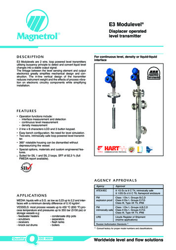
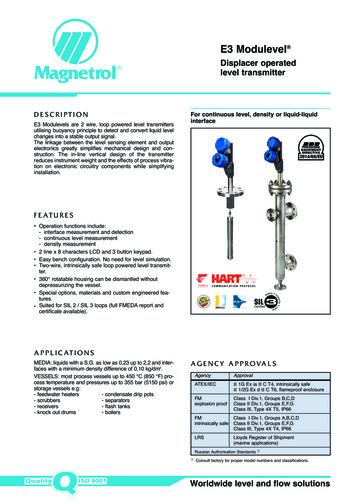
E3 Modulevel Displacer operatedlevel transmitter DESCRIPTIONE3 Modulevels are 2 wire, loop powered level transmittersutilising buoyancy principle to detect and convert liquid levelchanges into a stable output signal.The linkage between the level sensing element and outputelectronics greatly simplifies mechanical design and construction. The in-line vertical design of the transmitterreduces instrument weight and the effects of process vibration on electronic circuitry components while simplifyinginstallation.For continuous level, density or liquid-liquidinterface2014/68/EUF E AT U R E S Operation functions include: - interface measurement and detection- continuous level measurement- density measurement2 line x 8 characters LCD and 3 button keypad.Easy bench configuration. No need for level simulation.Two-wire, intrinsically safe loop powered level transmitter.360 rotatable housing can be dismantled withoutdepressurizing the vessel.Special options, materials and custom engineered features.Suited for SIL 2 / SIL 3 loops (full FMEDA report andcertificate available).A P P L I C AT I O N SMEDIA: liquids with a S.G. as low as 0,23 up to 2,2 and interfaces with a minimum density difference of 0,10 kg/dm3.VESSELS: most process vessels up to 450 C (850 F) process temperature and pressures up to 355 bar (5150 psi) orstorage vessels e.g:- feedwater heaters- condensate drip pots- scrubbers- separators- receivers- flash tanks- knock out drums- boilersA G E N C Y A P P R O VA L SAgencyApprovalATEX/IECII 1G Ex ia II C T4, intrinsically safeII 1/2G Ex d II C T6, flameproof enclosureFMintrinsically safeClass I Div.1, Groups A,B,C,DClass II Div.1, Groups E,F,GClass III, Type 4X T4, IP66FMexplosion proofLRSClass I Div.1, Groups B,C,DClass II Div.1, Groups E,F,GClass III, Type 4X T5, IP66Lloyds Register of Shipment(marine applications)Russian Authorisation Standards ¿¿ Consult factory for proper model numbers and classifications.Worldwide level and flow solutions
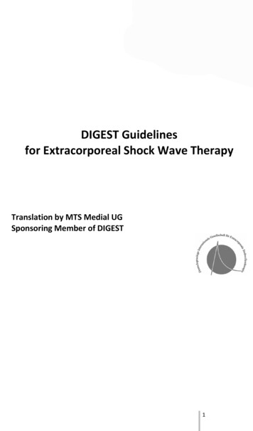
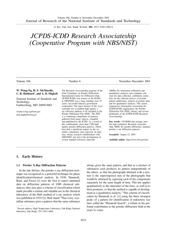
P R I N C I P L E O F O P E R AT I O NLevelLiquid level change acts upon the range spring supporteddisplacer causing vertical motion of a core within a linearvariable differential transformer (LVDT).The enclosing tube acts as a static isolation barrierbetween the LVDT and the process media.As core position changes with liquid level, voltages areinduced in the secondary windings of the LVDT.These signals are processed in the electronic circuitry andused to control the output signal.InterfaceE3 Modulevel is capable of tracking the interface level oftwo immiscible liquids with different densities. Each unit iscustom-made with a displacer specially designed for theuser’s application. This allows it to detect the position of aclean interface or an emulsion layer and convert it into astable output signal. Contact the factory for assistance inspecifying an E3 for interface service. Note that for properinterface detection, the entire displacer must always beimmersed in liquid.LVDTMoving LVDT CoreElectronics incl.digital display /3 button key padEnclosing tubeRange springSpring protection capDisplacerExternal cageDensityYet another capability of E3 Modulevel is to track thechanging density of a liquid over a known density rangeand convert that into a stable output signal. As the density of the liquid changes, so does the mass of the liquid displaced by the specially designed displacer. The resultingchange in buoyancy force on the displacer causes themovement of the LVDT core necessary to convert the density change to the output signal.P A C T w a r e P C S O F T WA R E P R O G R A MFDT technology provides an open communication interface between field instruments of various communicationprotocols and the host/ DCS system. The DTM driver istypical for one type of instrument and delivers the fullfunctionality of the device added with graphical userinterface via a laptop or PC. Magnetrol transmitters usethe free shareware PACTware software to supportDTM drivers and the FDT functionality. Via PACTware it becomes easy to configure, monitor and diagnose aMagnetrol transmitter from distance or even to call forfactory assistance over the internet via the supply ofscreenshots of on-line parameters and trending graphs.Magnetrol DTM library HART has passed thedtmINSPECTOR, the official FDT interoperability test andcertification tool. The Magnetrol DTM’s are free of chargeand can be downloaded from www.magnetrol.com.2Magnetrol recommends the VIATOR USB HART Interfacefrom MACTek Corporation.
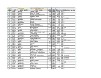
MOUNTINGE31/E32OilWaterE35/E36E33/E34EXPEDITE SHIP PLAN (ESP)Several models are available for quick shipment, within max. 4 weeks after factory receipt of purchase order, through theExpedite Ship Plan (ESP).Models covered by ESP service are conveniently colour coded in the selection data charts.To take advantage of ESP, simply match the colour coded model number codes (standard dimensions apply).ESP service may not apply to orders of five units or more. Contact your local representative for lead times on larger volumeorders, as well as other products and options.S E L E C T I O N D ATAA complete measuring system consists of:1. One order code for a complete E3 Modulevel transmitter.2. Options:- Adjustable displacer hanger for top mounted units, cable length 2,5 m (8'). Order code 032-3110-004 – requiredwhen distance between the top of the displacer and the flange face is dimension A (see section Dimensions) 60 mm (2.36").- Free of charge: E3 Modulevel DTM (PACTware ) can be downloaded from www.magnetrol.com.- Connecting cable used with remote mount electronics (6-wire cable/shielded, not suitable for ATEX/IEC flameproofenclosure). Consult factory for connecting cable suitable for ATEX/IEC flameproof enclosure.1 3 73 2 2 70 0 1 - 0 2 3 From 1 m (3,28 ft) min. to 23 m (75,46 ft) max.Specify in increments of 1 m (3,28 ft)complete order code for connecting cable3
S E L E C T I O N D ATA – N O N S T E A M a p p l i c a t i o n s ( m a x 6 0 0 l b s )BASIC MODEL NuMBERCarbon steel modelsE 3 1E 3 3E 3 5Stainless steel modelstop mounted E3 ModulevelE3 Modulevel with side/bottom cageE3 Modulevel with side/side cageE 3 2E 3 4E 3 6top mounted E3 ModulevelE3 Modulevel with side/bottom cageE3 Modulevel with side/side cageSPECIFIC GRAVITY AND PROCESS TEMPERATuRE (consult factory for interface applications)Match temperature extensions with max. process temperature (digit 9)150 C200 C230 C290 C315 C400 C450 C max. temp. / S.G.JAMDM––0.23 - 0.54 specific gravityKBNENNE0.55 - 1.09 specific gravityLCPFP––1.10 - 2.20 specific gravityPROCESS CONNECTIONFor top mounted connection type150 lbsRFG3H3K3E31/E32 - ANSI Flange rating600 lbs300 lbsRFRFRJG4G5GKH4H5HKK4K5KKSize3"4"6"For external cage modelsE33 . E36 - ANSI Flange/Cage rating600 lbs150 lbs 300 lbsSizeRFRFRFRJP3Q3A3E3R3F3P4Q4A4E4R4F4P5Q5LEVEL RANGE35614A81332BA5E5R5F5121948CPKQK11/2" flanged2" flanged11/2" NPT-F2" NPT-F11/2" S.W.2" S.W.152460DEAFAGAEEFEGEDN 80DN 100DN 150DN 40flangedCCCDCEDADCDDDEDN ode4-20 mA with Hart , SIL 2/3 certified (incl. display / 3 button keypad)FOuNDATION Fieldbus communication (incl. display / 3 button keypad)MAX PROCESS TEMPERATuREMatch max. process temperature with temperature extensions (digit 4)Integral mount electronics13T 290 C ( 550 F) 290 C ( 550 F) T 315 C ( 600 F)– digit 4: ALL– digit 4: M, N or P8 315 C ( 600 F) T 450 C ( 850 F)– digit 4: N or EAPPROVALS & HOuSINGCast aluminiumNPT M20JKABEF56123/4"4EDFDGDCARemote mount electronicsE 3ECFCGCE33 . E36 - EN 1092-1 (DIN) Flange ratingPN 16 PN 25/40 PN 63PN 100SizeType B1 Type B1 Type B2 Type B2182972OuTPuT AND ELECTRONICSSFE31/E32 - EN 1092-1 (DIN) Flange ratingPN 16 PN 25/40 PN 63PN 100SizeType B1 Type B1 Type B2 Type B2Stainless SteelNPT M20LMCDGH78343/4"Housing materialCable entryApprovalWeatherproofATEX/IEC and FISCO intrinsically safeATEX/IEC (Hart and FF) flameproof enclosureFM and FISCO intrinsically safeFM (Hart and FF) Explosion proofcomplete order code for E3 Modulevel transmitter –nOn STEAM applicationsX product with a specific customer requirement
S E L E C T I O N D ATA – S T E A M a p p l i c a t i o n s ( m a x 6 0 0 l b s )BASIC MODEL NuMBERCarbon steel modelsE 3 1E 3 3E 3 5Stainless steel modelstop mounted E3 ModulevelE3 Modulevel with side/bottom cageE3 Modulevel with side/side cageE 3 2E 3 4E 3 6top mounted E3 ModulevelE3 Modulevel with side/bottom cageE3 Modulevel with side/side cageSPECIFIC GRAVITY AND PROCESS TEMPERATuRE (consult factory for interface applications)Match temperature extensions with max. process temperature (digit 9)150 CK200 CB230 CN260 CE370 CNPROCESS CONNECTIONFor top mounted connection type150 lbsRFG3H3K3E31/E32 - ANSI Flange rating600 lbs300 lbsRFRFRJG4G5GKH4H5HKK4K5KKSize3"4"6"For external cage modelsE33 . E36 - ANSI Flange/Cage rating600 lbs150 lbs 300 lbsSizeRFRFRFRJP3Q3A3E3R3F3P4Q4A4E4R4F4P5Q5LEVEL RANGE35614A81332BA5E5R5F5121948CPKQK11/2" flanged2" flanged11/2" NPT-F2" NPT-F11/2" S.W.2" S.W.152460D182972OuTPuT AND ELECTRONICSSFEE31/E32 - EN 1092-1 (DIN) Flange ratingPN 16 PN 25/40 PN 63PN 100SizeType B1 Type B1 Type B2 Type B2EAFAGAECFCGCEDFDGDEEFEGEDN 80DN 100DN 150E33 . E36 - EN 1092-1 (DIN) Flange ratingPN 16 PN 25/40 PN 63PN 100SizeType B1 Type B1 Type B2 Type B2DN 40flangedCACCCDCEDADCDDDEDN de4-20 mA with Hart , SIL 2/3 certified (incl. display / 3 button keypad)FOuNDATION Fieldbus communication (incl. display / 3 button keypad)MAX PROCESS TEMPERATuREMatch max. process temperature with temperature extensions (digit 4)Integral mount electronics123T 150 C ( 300 F) 150 C ( 300 F) T 230 C ( 450 F) 230 C ( 450 F) T 260 C ( 500 F)– digit 4: K– digit 4: B or N– digit 4: E8 260 C ( 500 F) T 425 C ( 800 F)– digit 4: N or ERemote mount electronicsAPPROVALS & HOuSINGCast aluminiumNPT M20JKABEF56123/4"E 3max. temp. / S.G.0.55 - 1.09 specific gravity425 CEStainless SteelNPT M20LMCDGH78343/4"Housing materialCable entryApprovalWeatherproofATEX/IEC and FISCO intrinsically safeATEX/IEC (Hart and FF) flameproof enclosureFM and FISCO intrinsically safeFM (Hart and FF) Explosion proofcomplete order code for E3 Modulevel transmitter –STEAM applicationsX product with a specific customer requirement5
S E L E C T I O N D ATA – N O N S T E A M a p p l i c a t i o n s ( f r o m 9 0 0 l b s t o 2 5 0 0 l b s )BASIC MODEL NuMBERCarbon steel modelsE 3 1E 3 3E 3 5Stainless steel modelstop mounted E3 ModulevelE3 Modulevel with side/bottom cageE3 Modulevel with side/side cageE 3 2E 3 4E 3 6top mounted E3 ModulevelE3 Modulevel with side/bottom cageE3 Modulevel with side/side cageSPECIFIC GRAVITY AND PROCESS TEMPERATuRE (consult factory for interface applications)Match temperature extensions with max. process temperature (digit 9)150 CK200 CB230 CN290 CE315 CNPROCESS CONNECTIONFor top mounted connection typeE31/E32 - ANSI Flange rating900 lbs1500 lbs2500 lbsRJRJRJ ➀GL––HLHMHNKLKMKN400 CN3"4"6"E33.E36 - ANSI Flange/Cage rating900 lbs1500 lbs2500 lbsRJRJRJ ➀PLPMPNQLQMQNALAMANELEMENRLRMRNFLFMFNmax. temp. / S.G.0.55 - 1.09 specific gravityE31/E32 - EN 1092-1 (DIN) Flange ratingPN 160PN 250PN 320Type B2Type B2Type B2EFEGEHFFFGFHGFGGGHSizeFor external cage models450 CESize1 1/2" flanged2" flanged1 1/2" NPT-F2" NPT-F1 1/2" S.W.2" S.W.E33.E36 - EN 1092-1 (DIN) Flange ratingPN 160PN 250PN 320Type B2Type B2Type uT AND ELECTRONICSSFE213484DN 40flanged3048120HImminchescodeMAX PROCESS TEMPERATuREMatch max. process temperature with temperature extensions (digit 4)Integral mount electronics13T 290 C ( 550 F) 290 C ( 550 F) T 315 C ( 600 F)– digit 4: ALL– digit 4: N8 315 C ( 600 F) T 450 C ( 850 F)– digit 4: N or EAPPROVALS & HOuSINGCast aluminium3/4" NPTM20JKABEF56126G2743108Size4-20 mA with Hart , SIL 2/3 certified (incl. display / 3 button keypad)FOuNDATION Fieldbus communication (incl. display / 3 button keypad)Remote mount electronicsE 3F243896DN 80DN 100DN 150DN 50flanged➀ Max. 355 bar (5150 psig) @ 40 C ( 100 F)LEVEL RANGESizeStainless SteelNPT M20LMCDGH78343/4"Housing materialCable entryApprovalWeatherproofATEX/IEC and FISCO intrinsically safeATEX/IEC (Hart and FF) flameproof enclosureFM and FISCO intrinsically safeFM (Hart and FF) Explosion proofcomplete order code for E3 Modulevel transmitter –nOn STEAM applications / high pressureX product with a specific customer requirement
S E L E C T I O N D ATA – S T E A M a p p l i c a t i o n s ( f r o m 9 0 0 l b s t o 2 5 0 0 l b s )BASIC MODEL NuMBERCarbon steel modelsE 3 1E 3 3E 3 5Stainless steel modelstop mounted E3 ModulevelE3 Modulevel with side/bottom cageE3 Modulevel with side/side cageE 3 2E 3 4E 3 6top mounted E3 ModulevelE3 Modulevel with side/bottom cageE3 Modulevel with side/side cageSPECIFIC GRAVITY AND PROCESS TEMPERATuRE (consult factory for interface applications)Match temperature extensions with max. process temperature (digit 9)150 CK200 CB230 CN260 CE370 CNPROCESS CONNECTIONFor top mounted connection typeE31/E32 - ANSI Flange rating900 lbs1500 lbs2500 lbsRJRJRJ ➀GL––HLHMHNKLKMKNE31/E32 - EN 1092-1 (DIN) Flange ratingPN 160PN 250PN 320Type B2Type B2Type B2EFEGEHFFFGFHGFGGGHSize3"4"6"For external cage modelsE33.E36 - ANSI Flange/Cage rating900 lbs1500 lbs2500 lbsRJRJRJ ➀PLPMPNQLQMQNALAMANELEMENRLRMRNFLFMFNmax. temp. / S.G.0.55 - 1.09 specific gravity425 CESize1 1/2" flanged2" flanged1 1/2" NPT-F2" NPT-F1 1/2" S.W.2" S.W.E33.E36 - EN 1092-1 (DIN) Flange ratingPN 160PN 250PN 320Type B2Type B2Type uT AND ELECTRONICSSFE213484G27431083048120HSizeDN 40flangedImminchescode4-20 mA with Hart , SIL 2/3 certified (incl. display / 3 button keypad)FOuNDATION Fieldbus communication (incl. display / 3 button keypad)MAX PROCESS TEMPERATuREMatch max. process temperature with temperature extensions (digit 4)Integral mount electronics123T 150 C ( 300 F) 150 C ( 300 F) T 230 C ( 450 F) 230 C ( 450 F) T 260 C ( 500 F)– digit 4: K– digit 4: B or N– digit 4: E8 260 C ( 500 F) T 425 C ( 800 F)– digit 4: N or ERemote mount electronicsAPPROVALS & HOuSINGCast aluminiumNPT M20JKABEF56123/4"E 3F243896DN 80DN 100DN 150DN 50flanged➀ Max. 355 bar (5150 psig) @ 40 C ( 100 F)LEVEL RANGESizeStainless SteelNPT M20LMCDGH78343/4"Housing materialCable entryApprovalWeatherproofATEX/IEC and FISCO intrinsically safeATEX/IEC (Hart and FF) flameproof enclosureFM and FISCO intrinsically safeFM (Hart and FF) Explosion proofcomplete order code for E3 Modulevel transmitter –STEAM applications / high pressureX product with a specific customer requirement7
T R A N S M I T T E R S P E C I F I C AT I O N SFUnCTIOnAL/PHYSICALDescriptionPower (at terminals)SpecificationWeatherproof / Intrinsically Safe: 11 to 28,4 V DC (ATEX/IEC) - 28,6 V DC (FM)ATEX/IEC flameproof enclosure 11 to 36 V DC (ATEX/IEC-FM)FOuNDATION Fieldbus (FISCO Intrinsically Safe): 9 to 17,5 V DCFOuNDATION Fieldbus (Explosion proof): 9 to 32 V DC4-20 mA with HART , 3,8 mA to 20,5 mA useable (meets NAMuR NE 43),FOuNDATION Fieldbus H1 (ITK Ver. 5)Signal OutputSpanfrom 356 mm up to 3048 mm (14" up to 120") - others at requestResolutionAnalog: 0,01 mADisplay: 0,1 cm (inch)Loop ResistanceDampingDiagnostic Alarmuser Interface620 Ω @ 20,5 mA - 24 V DCAdjustable 0-45 sAdjustable 3,6 mA, 22 mA, HOLDHART communicator, AMS or PACTware , FOuNDATION Fieldbus and 3-button keypadDisplayMenu LanguageHousing MaterialApprovals2-line x 8-character LCDEnglish/Spanish/French/German (FOuNDATION Fieldbus : English)IP 66/Aluminium A356T6 ( 0.20 % copper) or stainless steelATEX/IEC II 1 G Ex ia IIC T4, intrinsically safeATEX/IEC II 1 G Ex ia IIC T4, FISCO – intrinsically safeATEX/IEC II 1 / 2 G Ex d IIC T6, flameproof enclosureFM, Intrinsically Safe (FISCO) and explosion proofFOuNDATION Fieldbus units are FISCO (intrinsically safe) and ATEX/IEC – FM/CSAexplosion proof approvedSIL➀ (Safety Integrity Level)Electrical DataEquivalent DataShock/Vibration Class➁Net and Gross Weight Cast aluminiumStainless steelOverall DimensionsFOuNDATIONITK VersionFieldbus specificaH1 Device ClasstionsH1 Profile ClassFunction BlocksQuiescent current drawExecution timeCFF filesLRS – Lloyds Register of Shipping (marine applications)ROSTECH/FSTS – Russian Authorisation StandardsFunctional safety to SIL 2 as 1oo1 in accordance to 61508 – SFF of 90,6 %Certified for use in SIL 3 loops.ui 28,4 V, li 94 mA, Pi 0,67 W - ATEX/IECui 28,6 V, li 140 mA, Pi 1 W - FMui 17,5 V, li 380 mA, Pi 5,32 W (FOuNDATION Fieldbus)Ci 2,2 nF, Li 3 µH - ATEX/IECCi 5,5 nF, Li 9 µH - FMCi 0,71 nF, Li 3 µH (FOuNDATION Fieldbus )ANSI/ISA-S71.03 SA1 (Shock), ANSI/ISA-S71.03 VC2 (Vibration)3 kg (7 lbs) – transmitter head / electronics only8 kg (17 lbs) – transmitter head / electronics onlyH 306 mm (12.05") x W 112 mm (4.41") x D 192 mm (7.56")5.0Link Master (LAS) – selectable ON/OFF31PS, 32L1 x AI and 1 x PID, 1 x RB, 1 x TB17 mAAI: 15 ms, PID: 40 msDownloads available from Host system supplier or www.fieldbus.org➀ Not applicable for FOuNDATION Fieldbus units.➁ With aluminium housing only. Does not apply to models with stainless steel housing.8
esisResponse timeWarm-up ace/Density 0,50 % of full 0,70 % of full 0,05 % of full 0,10 % of full 0,05 % of full 1 second 5 secondsAmbient Temp.Storage temperatureAmbient Temp. EffectProcess Temp.spanspanspanspanspan-40 C to 80 C (-40 F to 175 F)-20 C to 70 C (-5 F to 160 F)-40 C to 70 C (-40 F to 160 F)– electronics temperature range– LCD temperature range– for Ex ia and Ex d units-40 C to 85 C (-40 F to 185 F)Max zero shift is 0,03 % / C (0,017 % / F) 425 C ( 800 F) for steam / 450 C ( 850 F) for non steam-30 C (-20 F) for carbon steel models / -196 C (-320 F) for stainless steel models355 bar @ 40 C (5150 psi @ 100 F)from 0,23 kg/dm3 up to 2,20 kg/dm30-99 %, non-condensingMeets CE requirements (EN 61326: 1997 A1 A2)Meets CE EN 61326 (1000V)MaxMinMax Process PressureDensity RangeHumidityElectromagnetic compatibilitySurge ProtectionM E C H A N I C A L S P E C I F I C AT I O N SDescriptionCage materialsWetted partsProcess ConnectionSpecificationcarbon steel or 316/316L (1.4401/1.4404) (other materials at request)Inconel (other materials at request)316/316L (1.4401/1.4404) or 316 (1.4401)Threaded: 1 1/2" NPT-F or 2" NPT-F or 1 1/2" Socket Weld or 2" Socket WeldFlanged: Various ANSI or EN/DIN flangesFrom 356 mm (14") up to 3048 mm (120") - other lengths at requestSpringDisplacerDisplacer lengthsELECTRICAL WIRINGSafe areaHazardousareaI.S.0%100 %AMS FDT/PACTware 9
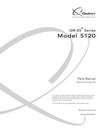
DIMENSIONS in mm (inches)Transmitter HeadIntegralRemote102 (4.02)cable entry105(4.12)83(3.28)102 (4.02)235 (9.25)cable entry22(0.87)262(10.32)72(2.81)27 (1.06)98(3.86)Ø 9,5 (0.37)100(3.95)159(6.28)103(4.04)70 89(3.50)70(2.75)Cable must be ordered separately(refer to section “Selection data / Options”).cable entrySide/bottom cageE33/E34 - J/K/LSide/side cageE35/E36 - J/K/L407 (16)407 (16)ALevelRangeAALevelRange 2 (0.08)LevelRange 2 (0.08)LevelRange 2 (0.08)133 (5.24)133 (5.24)C1" nPT-F drain(plug not supplied)BBTemperature extensions407 (16)A133 (5.24)IntegralBRemoteDigit 4Dim. DDigit 4Dim. DM, N, P610 (24)E701 (27.6)A, B, C10cable entry167 (6.57)Side/bottom cageE33/E34 - J/K/LD295(11.61)45 206(8.10)Top MountedE31/E32 - J/K/L407 (16)143(5.63)D, E, F508 (20)712 (28)ND600 (23.6)
DIMENSIONS in mm (inches)Dimension A for all modelsCage rating150 / 300 / 600 lbsPN 16 . PN 100900 / 1500 lbsPN 160 / PN 2502500 lbsPN 320150 / 300 / 600 lbsPN 16 . PN 100900 / 1500 lbsPN 160 / PN 2502500 lbsPN 320SG range0.23 - 0.540.55 - 1.091.10 - 2.200.55 - 1.090.55 - 1.094 th digit9 th digitJ/A/M/DK/B/N/EDimension A236 (9.29)186 (7.32)1/2/3L/C/P/FK/B/N/E186 (7.32)245 (9.65)1/2/3N/E320 (12.60)236 (9.29)8245 (9.65)320 (12.60)Dimensions B and C for external cage models (E33/E34/E35/E36)Flanged process connectionsFlange size1 1/2"Flange ratingDN 401 1/2"2"C180 (7.09)180 (7.09)195 (7.68)186 (7.32)229 (9.02)268 (10.55)268 (10.55)281 (11.06)281 (11.06)313 (12.32)PN 16 / PN 25 / PN 40PN 63 / PN 100PN 160PN 250PN 320EN 1092-1 Type B1EN 1092-1 Type B2EN 1092-1 Type B2EN 1092-1 Type B2EN 1092-1 Type B2180 (7.09)200 (7.87)200 (7.87)consult factoryconsult factory268 (10.55)288 (11.34)consult factoryconsult factoryconsult factoryThreaded / Socket weld process connectionsSizeDimensionsSlip on - ANSI RFWeldneck - ANSI RJWeldneck - ANSI RJWeldneck - ANSI RJWeldneck - ANSI RJPN 16PN 25 / 40PN 63PN 100PN 160PN 250PN 320DN 50B150 / 300 / 600 lbs600 lbs900 lbs1500 lbs2500 lbs150 / 300 / 600 lbs600 lbs900 lbs1500 lbs2500 lbs2"Connection typeCage rating150 / 300 / 600 / 900 lbs1500 lbs2500 lbs150 / 300 / 600 / 900 lbs1500 lbs2500 lbsSlip on - ANSI RFWeldneck - ANSI RJWeldneck - ANSI RJWeldneck - ANSI RJWeldneck - ANSI RJEN 1092-1 Type B1EN 1092-1 Type B1EN 1092-1 Type B2EN 1092-1 Type B2EN 1092-1 Type B2EN 1092-1 Type B2EN 1092-1 Type B2Connection typeNPT/SWNPT/SWNPT/SWNPT/SWNPT/SWNPT/SW185 (7.28)185 (7.28)215 (8.46)212 (8.35)250 (9.84)185 (7.28)188 (7.40)202 (7.95)208 (8.19)215 (8.46)consult factoryconsult factoryB273 (10.75)273 (10.75)302 (11.89)302 (11.89)329 (12.95)273 (10.75)276 (10.87)293 (11.54)299 (11.77)consult factoryconsult factoryconsult factoryDimensions81 (3.19)89 (3.50)102 (4.02)84 (3.31)98 (3.86)111 (4.37)CNotApplicable11
QUALITY ASSURAnCE - ISO 9001:2008THE QuALITY ASSuRANCE SYSTEM IN PLACE AT MAGNETROL GuARANTEES THE HIGHEST LEVEL OF QuALITY DuRING THE DESIGN,THE CONSTRuCTION AND THE SERVICE OF CONTROLS.OuR QuALITY ASSuRANCE SYSTEM IS APPROVED AND CERTIFIED TO ISO 9001:2008 AND OuR TOTAL COMPANY IS COMMITTED TOPROVIDING FuLL CuSTOMER SATISFACTION BOTH IN QuALITY PRODuCTS AND QuALITY SERVICE.PRODUCT WARRAnTYALL E3 MODuLEVEL LEVEL TRANSMITTERS ARE WARRANTED FREE OF DEFECTS IN MATERIALS AND WORKMANSHIP FOR18 MONTHS FROM THE DATE OF ORIGINAL FACTORY SHIPMENT.IF RETuRNED WITHIN THE WARRANTY PERIOD; AND, uPON FACTORY INSPECTION OF THE CONTROL, THE CAuSE OF THE CLAIM IS DETERMINED TO BE COVEREDuNDER THE WARRANTY; THEN, MAGNETROL INTERNATIONAL WILL REPAIR OR REPLACE THE CONTROL AT NO COST TO THE PuRCHASER (OR OWNER) OTHER THANTRANSPORTATION.MAGNETROL SHALL NOT BE LIABLE FOR MISAPPLICATION, LABOR CLAIMS, DIRECT OR CONSEQuENTIAL DAMAGE OR EXPENSE ARISING FROM THE INSTALLATIONOR uSE OF THE EQuIPMENT. THERE ARE NO OTHER WARRANTIES EXPRESSED OR IMPLIED, EXCEPT, SPECIAL WRITTEN WARRANTIES COVERING SOMEMAGNETROL PRODuCTS.:2008BuLLETIN N :EFFECTIVE:SuPERSEDES:uNDER RESERVE OF MODIFICATIONSHeikensstraat 6, 9240 Zele, België -BelgiqueTel. 32 (0)52.45.11.11 Fax. 32 (0)52.45.09.93 E-Mail: info@magnetrol.beDEUTSCHLANDAlte Ziegelei 2-4, D-51491 OverathTel. 49 (0)2204 / 9536-0 Fax. 49 (0)2204 / 9536-53 E-Mail: vertrieb@magnetrol.deINDIAB-506, Sagar Tech Plaza, Saki Naka Junction, Andheri (E), Mumbai - 400072Tel. 91 22 2850 7903 Fax. 91 22 2850 7904 E-Mail: info@magnetrolindia.comITALIAVia Arese 12, I-20159 MilanoTel. 39 02 607.22.98 Fax. 39 02 668.66.52 E-Mail: mit.gen@magnetrol.itRUSSIABusiness center “Farvater”, Ruzovskaya Street 8B, office 400A, 190013 St. PetersburgTel. 7 812 320 70 87 E-Mail: info@magnetrol.ruPO Box 261454 JAFZA LIU FZS1 – BA03, Jebel AliTel. 971 4 880 63 45 Fax 971 4 880 63 46 E-Mail: info@magnetrol.aeU.A.E.UNITEDKINGDOMUnit 1 Regent Business Centre, Jubilee Road Burgess Hill West Sussex RH 15 9TLTel. 44 (0)1444 871313 Fax 44 (0)1444 871317 E-Mail: EOUR nEAREST REPRESEnTATIVEBE 48-135.3APRIL 2017August 2016
3 MOUNTING Oil Water E35/E36 E31/E32 E33/E34 EXPEDITE SHIP PLAN (ESP) Several models are available for quick shipment, within max. 4 weeks after factory receipt of purchase order, through the