Transcription
Development of an Automated Guided Vehicle for Tractor AssemblybySabeethan KanagasinghamA capstone project report submitted in partial fulfillment of the requirements for thedegree of Bachelor of Science in Engineering inMechatronics EngineeringExamination Committee:Nationality:Dr. Manukid Parnichkun (Chairperson)Dr. Mongkol Ekpanyapong (Member)Assoc. Prof. Erik L. J. Bohez (Member)Sri LankanAsian Institute of TechnologySchool of Engineering and TechnologyThailandMay 2014
AcknowledgementsFirst and foremost, I would like to extend my heartfelt gratitude to my academic advisorand chairperson, Dr. Manukid Parnichkun for all the guidance and encouragementthroughout this project. I would also like to thank the committee members Dr. MongkolEkpanyapong and Ir. Erik Bohez for their support and advice given to improve my project.I take this opportunity to thank the Manager of Production Engineering at SIAM Kubota,Mr. Methee Srisupundit for allowing me to uptake the company’s project as my capstoneand for all his assistance in completing this project. I would also like to extend my sinceregratefulness to Mr. Thouchapol Jiramoree, Electrical Engineer at SIAM Kubota for hiscontinuous assistance and the valuable knowledge provided throughout the project withoutwhich I could not have achieved the objectives in time.Lastly, I thank all my faculty members, staff, friends and family for all their supportthrough all my hard times. I would like to extend a special note of gratitude to my deceasedfather without whom I would not have pursued this degree and or gained the determinationto succeed in the challenge entrusted upon me.
AbstractAs advancement in automation and control enter a new era in technological development,the need to keep up with these advancements is paramount. Automating process that take alot of labor and lead time could make a lot of difference in those annual documents thatevaluates the company’s performances. SIAM Kubota has been well aware and very keenin automating their processes in the tractor manufacturing to measure up in the highlycompetitive market. This paper provides a automation solution to an otherwise tedious,time consuming and rather inefficient process of transferring machined products from itsmachining center to storage racks. The project involves the designing of the mechanicalsystem integrated with electrical system and control of an Automated Guided Vehicle thatwould replace the existing labor-handled trolley. The project aims at providing a fullyfunctional, economic, automated system to meet industrial standards and requirements.ii
Table of ContentsChapterTitlePageTitle PageAcknowledgementAbstractTable of ContentsList of FiguresList of oblem Statement1.3Objectives1.4Scope112222Literature Review2.1Information2.2Autonomous Mobile Robots2.3Automated Guided Vehicles2.4Design of AGV444453Methodology3.1Guide Path Design3.2Mechanical Design3.3Electrical Design3.4Programming and Control3.5Assembly7771315184Test and Results4.1Manual Mode – Part Intake and Output4.2Manual Mode – AGV free run4.3Automatic Mode – Rack Selection4.4Automatic Mode – AGV navigation, rack detection, partdelivery and return to home21222324245Total Cost266Conclusion and 277References298Appendix31iii
List of .93.103.113.123.134.14.24.34.44.54.64.74.8The framework for designSolid Works model of AGV designImages of AGVSolid Works model of Square Bar and C-ChannelSolid Works model of Rollers, Sprocket and CasterSolid Works model of custom designed partsSolid Works model of Trolley DesignImages of TrolleyBidirectional Control using relaysSensor Logic For Motor ControlFlow Chart for Main programFlow Chart for the “AGV Navigation” subroutineImages of Control BoxImage of completed Trolley assembled with AGVRoute for AGVImage of Test route layoutImage of Control PanelImage of Manual Mode Operation – Part IntakeImage of Manual Mode Operation – Part OutputImage of AGV taking left turnImage of Rack SelectionImages of Trolley in operation in Auto Modeiv68910111112121416171819202121222223232425
List of TablesTableTitlePage5.1Total Cost of AGV and Trolleyv26
Chapter 1Introduction1.1Background“Most of us have heard the popular phrase “Innovate or Die” in recent years. Let mesuggest a spin on it - Automate or Die!” says Lara Sowinski in her article for Food andLogistics. She affirms this statement by relating to how modern customers order productsat all times of the day and expect it to be delivered at express speed. The answer to thisincessant demand is automation (Sowinski, 2013). Since its inception in the 18th century inthe form of an automatic governor, automation has been embraced by almost all factoriesfrom around the world. Automation has enabled companies to achieve astounding speedsand efficiency and a faster throughput in their manufacturing processes which would havebeen otherwise inconceivable.Siam Kubota, a joint venture between Kubota Corporation (Japan) and Siam CementGroup Thailand (About Us, 2011) has not been exempted from the heavy competition andunmatchable demands that any factory around the world is confronted with. The mainassembly lines, which are situated in the factory located in Amata Nakorn Industrial Estatein Chonburi, Thailand, utilize various forms of automation to efficiently endure in thehighly competitive market. With the ever increasing demand and competition, the need formore automation and optimization of its assembly lines is imminent.In the process of exploring for more opportunities to automate and improve the factory,engineers have realized that the process of transferring machined (the process of removingmaterial from a raw material to desired shapes and sizes) raw materials to its storage racksneeds improvement. The current process is carried out by laborers who push the rawmaterial around on trolleys and load it into the storage racks.Implementation ofAutomated Guided Vehicles to transport these raw materials to their relevant storage rackscould potentially speed up the process and elevate its efficiency. Like Scott stone says inhis article for Cisco-Eagle, “Workflow is where hidden costs are in most operations”.Automating this process not only would improve the workflow but also would eliminatethe need for laborers to execute this process and hence would directly affect theprofitability of the company.1
1.2Problem StatementManufacturing of tractors involves raw materials such as gear boxes and transmissioncasings that need to be machined to custom requirements. These machined parts aretransferred to the storage racks by laborers who push them on a trolley. The parts are thenloaded onto the rack by the same laborer who pushes the other parts in to make way for thenew part. This procedure is found to be tedious, time consuming and rather inefficient.Automating this process could reduce the time taken for this transfer, while eliminating thelabor concerns and in turn improving the efficacy of the company. Hence the factory wouldbe largely benefitted by the implementation of an automated transfer system.1.3ObjectivesTo design and manufacture a working model of an automated, low cost, fully functionaltransfer mechanism for the raw materials from the machining center to the storage rack.1. To design and manufacture the mechanical system, electrical system and controlsystem of the AGV that would be utilized for transferring the parts.2. To design and implement the mechanical design, electrical system and the controlsystem of the trolley that will carry the parts.3. To allow for automatic intake and deliver of parts synced with the storage racks andoutput terminal of the machining line.1.4ScopeThe process automation will be done in two phases that need to be synced together: phase1 - the AGV and trolley that will transport the machined raw materials, phase 2 –automating the storage racks to intake and deliver raw materials as required. The AGVneeds to be able to be mounted to the bottom of the trolley.2
The Specifications of the AGV are as follows: Dimension300 x 260 x 190 Running Speed3 m/s (estimated maximum) Payload25 kg Travel Directionforward, turning Battery24 V, rechargeable CommunicationSwitches and buttons Guide PathReflective tape sensed by IR photo sensorsSpecification of Trolley Dimension Automated rollers to receive and return parts Sensors for obstacle detection500 x 620 x 620This thesis will only cover phase one of the automation process and will allow forcommunication with the storage racks. The phase 2 will be implemented by a colleaguewith whom, this project will be closely coordinated to ensure fully functional model.3
Chapter 2Literature review2.1InformationMaterial handling in factories has been an interesting topic of research and innovation. Themost common types of systems for material handling and transfer use Autonomous MobileRobots, Automatic Guided Vehicles or Conveyor Systems. Conveyor systems however aremost effective in the context of continuous mass transport (Vis, 2006).2.2Autonomous Mobile Robot“Autonomous Mobile Robots are a class of robots that have the capability to transportthemselves in three-dimensional space, independent of any guide paths and controlled byan external system or even entirely self-contained” says Paiboonying (2000). He furtherstates that most autonomous robots rely on wireless connection to a hub that provides theroutes and destinations for the robot to follow while some are even self-contained, whichmeans they can decide on their own the map and routes and do not rely on any externalsources (Paiboonying, 2000).2.3Automatic Guided VehicleAutomated Guided Vehicles are battery-powered, unmanned vehicles that can beprogrammed to select paths and positioning. They can be utilized in fully automatedcontrol systems making them ideal for material handling in job shop environments wherethere is a fluctuating transport (Bilge & Tanchoco, 1997). According to Vis (2006), AGV’sare used widely in industrial applications with repeating transportation patterns. He furtherexamines on how AGV’s have been implemented to boost efficiency in distribution,transshipment and transportation systems in environments such as warehouses and crossdocking centers, pallet transportation and container transportation. He adds that thespecifications of the AGV depends on the environment it is used in, i.e., a container yardmay need AGV’s capable of carrying weights of over 40 tons at least while less capacity isrequired in pallet transportation (Vis, 2006). This brings us to the concern of designing anAGV.4
2.3.1 Design of AGVKoff (1987) categorizes the requirements of designing an AGV as tactical and operationaldesign requirements. Tactical design requirements include the no. of AGV’s that need to beused, the time taken for a pickup and delivery, the number of pickup and delivery pointsand other system designing. Operational issues include the routing, the mechanical designof AGV, the sensors used, etc. Though many factors and decision variables may affect thedesign of an AGV, Koff suggests that at least the following tactical and operationalconcerns need to be addressed to design an AGV (Koff, 1987): Flow path layout, Traffic management: prediction and avoidance of collisions and deadlocks, Number and location of pick-up and delivery points, Vehicle requirements, Vehicle dispatching, Vehicle routing, Vehicle scheduling, Positioning of idle vehicles, Battery management, Failure management.Flow path layout which needs to be carefully designed in order to maximize throughputand traffic management could be addressed if the tandem AGV system as proposed first byKim and King is adopted where the AGV’s all move in the same direction in a loop (Kim& King, 1995). The number and location of pick-up and delivery points in this case is fixedand hence need not be determined.The vehicle requirements mainly include the physical components such as the hardware,controllers, sensors, and guidance devices. This phase of designing involves functionalspecifications and component specifications as stated by Jeroen Ploeg, Albert C.M. van derKnaap and Dirk J. Verhurg. (Ploeg, Knaap, & Verhurg, 2002, June). They also mention thekey aspects of vehicle requirements that include electric drives, the mechanical design andspecifications, the desired characteristics of the tyres, the battery package and the sensors.All these technical aspects need to be addressed to best meet the requirements.5
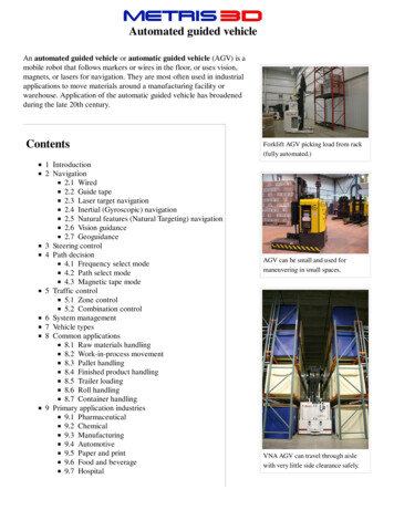
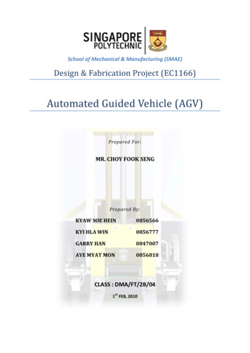
Vehicle dispatching, vehicle routing, scheduling and positioning of idle vehicles could beaddressed by adopting the loop topology model as described in a survey (QIU, HSU,HUANG, & WANG, 2002). The authors have also proposed many other algorithms forrouting and have mentioned that the loop topology is easiest to control and has nocollisions making it ideal for low to medium material handling.Tuan Le-Anh and M.B.M. De Koster signify the importance of battery management in theperformance of the AGV system (Le-Anh & Koster, 2006). It is necessary to consider thebattery charging cycles, the distance from the vehicle to the charging station and batteryswap options to ensure that a smooth flow exists in the material handling and that there isminimized lead time in the transfer process.The initial phase of the design process of this AGV will closely adhere to the frameworkproposed by Tuan Le-Anh and M.B.M. De Koster. This model suggests that the design willbe structured into a hierarchy as shown in Figure No. 2.1 where the process is divided intothree levels: the Strategic level, Tactical level and Operational level. The decisions at eachlevel influence the decisions made in other levels as indicated by arrows in this figure. Thismodel will only be a guideline for the design of the AGV with alterations made whennecessary.Figure No.2.1: The framework for design. Thickness of arrows corresponds tostrength of interrelationship. Source: (Le-Anh & Koster, 2006)6
Chapter 3Methodology3.1Guide Path DesignThe AGV follows a single loop guide path. The guide path comprises of black and whitereflective tape: 2” Black tape, with 1” white tape on both ends. Infrared sensors usingdiffuse-reflective methods detect the reflective papers and hence are guided along the path.Some of the key specifications of the sensor (Model: OMRON E3Z-D81) are as follows:Sensing Method:Diffuse ReflectiveSensing Distance:5mm to 100mmLight Source:Infrared LED (860nm)Power Supply:12 to 24 VDCCurrent Consumption:30 mA DC Max.Response Time:1ms Max.Output:PNP open collector typeThe number of sensors used (3 or 5) per AGV effects the smooth travel of the AGV. 5sensors will enable a much smoother travel. However, due to budget constraints, only 3sensors were used to maneuver the AGV. This was compensated for by using speedtransitions when taking turns for the AGV.3.2Mechanical DesignThe mechanical designs for both AGV and trolley were designed using Solidworks. Mostof the standard parts were selected from the Misumi Catalog and the relevant 3D CAD fileswere downloaded from their website.7
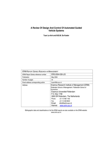
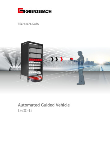
3.2.1Mechanical Design of AGVThe design for AGV was built from scratch. Existing working models of various AGV’swere reviewed and adopted. It was noted that two concerning factors that adversely affectthe performance of existing AGV’s were: Design Complexity – some designs were too complex, making it hard to build orrepair and also expensive. Suspensions – existing AGV’s did not compensate well for the irregularity of thefactory floor, hence causing unnecessary jerks and slips leading to unreliability.The design for the new AGV was targeted to address issues. Effectively, the AGV shouldbe a simple design that would allow for suspension to pitch and roll. The following designof the AGV was developed after many alterations and improvements.adbcFigure No.3.1: a) Top View of the Solid works model of AGV, b) Front View of theSolid works model of AGV, c) Side View of the Solid Works model of AGV, d)Isometric View of the Solid Works model of AGV8
As implied in the design, four springs and x-clip links were used to allow for pitch and rollof the AGV. The design uses as less materials as possible and is in its simplest form.The design allows for the AGV to rotate about the central axis by 360 . However this wasconstrained to less than 180 of rotation once the wires of the motors were installed.The AGV is made of Steel Sheets of different thicknesses. Though calculations orsimulations were not carried out due to lack of time to check the strength and robustness ofthe product, engineers at the company assured for enough strength to withstand payloads ofwell over 25 kg from experience.Drawings were prepared using Solid Works to meet company standards and orders wereplaced to manufacture the necessary parts. The drawings for the AGV are shown inAppendix A. Other components required for AGV were either bought from Misumi orretained from factory stores.The manufactured parts had faults in the position of certain holes and dimensions; hencesome of the parts had to be custom drilled at the workshop. The AGV was assembled in theworkshop and images of the assembled AGV are shown in the following figures.aabcFigure No.3.2: a) Image of AGV Top View, b) Image of AGV Side View, c) Image ofAGV Front View9
3.2.2Mechanical Design of TrolleySimilar to the AGV, the design for a Trolley was designed from scratch using Solid Works.The dimensions of the design were determined by analyzing the existing trolley. Theheight of the new design needed to be the same as existing trolleys to avoid having to alterthe delivery lines of the machine center. The length and width were determined in order toaccommodate one of the largest machined parts and to be able to be maneuvered.The framework of the trolley utilized steel square bars, C plates and sheets that could beeasily purchased in the market. Thai Metal Trade (TMT) datasheets were used to determinethe dimensions of the standard parts. Misumi catalog was utilized to insert caster wheels,sprockets and rollers to the trolley while a few components like the motor mount, wheelmount plates had to be designed to be custom machined.The following figures show designs of some of the parts used in the trolley.abFigure No.3.3: a) Solid Works Design of a Steel square bar, b) Solid Works design ofa C Channel. (Both parts were drawn to TMT specifications)10
abcFigure No.3.4: a) Solid Works Design of a Roller, b) Solid Works design of a IdlerSprocket, c) Solid Works design of a Caster (All 3 3D models were downloaded fromMisumi)abcFigure No.3.5: a) Solid Works Design of a Motor Mount Plate, b) Solid Works designof a Wheel Mount Plate, c) Solid Works design of a Battery Case (All 3 3D modelsneed to be custom machined)Standard drawings for the completed designs were prepared using Solid Works and orderswere placed to manufacture the trolley. The drawings for the trolley are shown inAppendix B while the following figures show the completed design and images for theassembled product.11
adbcFigure No.3.6: a) Top View of Trolley Design b) Front View of Trolley Design, c) SideView of Trolley Design, d) Isometric View of Trolley DesignadbcFigure No.3.7: a) Top View of Trolley b) Side View of Trolley, c) Front View ofTrolley, d) Isometric View of Trolley12
3.3Electrical DesignIt was decided that the AGV will be of multiple motor drive to avoid the mechanicalcomplexity of differential drives and the sorts. Since the AGV is to be mounted below thetrolley, the AGV does not have to take any load from the weight: it only has to provide theforward force and the maneuverability. Hence, two wheels controlled with a motor for eachwould be sufficient to accomplish this task. Vexta motors from “Oriental Motors” wereselected owing to their reasonable cost and availability at the factory. It also comes with amotor drive that can control the speed and direction of motor, making it ideal for thisapplication. The speed required for the AGV was calculated as follows.𝐴𝑠𝑠𝑢𝑚𝑖𝑛𝑔 𝑜𝑝𝑒𝑟𝑎𝑡𝑖𝑛𝑔 𝑠𝑝𝑒𝑒𝑑 1𝑚/𝑠𝑊ℎ𝑒𝑒𝑙 𝐷𝑖𝑎𝑚𝑒𝑡𝑒𝑟 150𝑚𝑚𝑚1𝑠 𝑅𝑜𝑡𝑎𝑡𝑖𝑜𝑛𝑎𝑙 𝑠𝑝𝑒𝑒𝑑 𝑜𝑓 𝑤ℎ𝑒𝑒𝑙 (2 𝜋 0.150)𝑚𝑟𝑒𝑣 1.06 𝑟𝑒𝑣/𝑠 63.6 𝑟𝑝𝑚𝑊𝑖𝑡ℎ 𝑎 𝑆𝑝𝑟𝑜𝑐𝑘𝑒𝑡 𝑅𝑎𝑡𝑖𝑜 𝑜𝑓 15: 40,𝑡ℎ𝑒 𝑒𝑓𝑓𝑒𝑐𝑡𝑖𝑣𝑒 𝑠𝑝𝑒𝑒𝑑 𝑜𝑓 𝑚𝑜𝑡𝑜𝑟 𝑟𝑒𝑞𝑢𝑖𝑟𝑒𝑑 𝑤𝑜𝑢𝑙𝑑 𝑏𝑒:15/40 63.6 23.9 𝑟𝑝𝑚The Motor Type BLH 450KC – 20 was selected since it had a range of incorporating therequired speed. The specifications of the motor are as follows: Output Power50W Power Supply24VDC Shaft/Gear TypeParallel Shaft Gearhead Gear Ratio20:1 Rated Torque3.6 Nm Variable Speed Range5 150 rpm (speed varied by analog input of 0-5V)Since the frictional coefficient of the floor of the factory was unknown, the exact torquerequired was not calculated. However, engineers assured with their personal experiencethat the rated torque of 3.6Nm from the motor was much more than sufficient.13
The rollers of the trolley need to move the parts in and out of the trolley. They need onlydirectional control and speed control is not necessary. Hence, a brushless DC motor withno speed control would be sufficient to implement the rollers. To achieve directionalcontrol, relays were used as shown in the following schematic.CR5CR5abFigure No.3.8: Bidirectional Control using Relays. a) Contact Relay CR4 – ON makesmotor rotates in one direction, b) Contact Relay CR5 – ON makes motor rotate in theopposite direction.The appropriate motor for this application needed to be determined. The followingcalculation was used to determine the speed of the motor required.𝐴𝑠𝑠𝑢𝑚𝑖𝑛𝑔 𝑡ℎ𝑎𝑡 𝑎 𝑝𝑎𝑟𝑡 𝑠ℎ𝑜𝑢𝑙𝑑 𝑚𝑜𝑣𝑒 150 𝑚𝑚 𝑖𝑠 𝑎 𝑠𝑒𝑐𝑜𝑛𝑑𝑖. 𝑒. 𝐿𝑖𝑛𝑒𝑎𝑟 𝑠𝑝𝑒𝑒𝑑 (𝑣) 0.15𝑚/𝑠𝐷𝑖𝑎𝑚𝑒𝑡𝑒𝑟 𝑜𝑓 𝑡ℎ𝑒 𝑟𝑜𝑙𝑙𝑒𝑟 (𝑑 ) 38 𝑚𝑚𝑟𝑒𝑞𝑢𝑖𝑟𝑒𝑑 𝑅𝑃𝑀 (𝑑𝑒𝑡𝑒𝑟𝑚𝑖𝑛𝑒𝑑 𝑓𝑟𝑜𝑚 𝑒𝑥𝑖𝑠𝑡𝑖𝑛𝑔 𝑡𝑟𝑜𝑙𝑙𝑒𝑦 𝑠𝑖𝑧𝑒𝑠)0.15𝑚/𝑠 60𝑠/𝑚𝑖𝑛 75𝑟𝑝𝑚(2 𝜋 0.019)𝑚/𝑟𝑒𝑣SPG motors were determined to be used owing to their reasonable costs and availability.The model S9D40 – 24B40 has the following specifications and was found to beappropriate for the trolley. Output Power40W Power Supply24VDC Gear Ratio40:1 Rated Torque3.86 Nm No Load RPM78 rpm14
Inductive sensors have been used to detect the availability of part on the rack. The modelused was one from OMRON (E2E-X10MF1). It is a DC, unshielded model of effectivesensing distance of up to10mm.The AGV and trolley are powered by four 12V, 22Ah Sealed Lead-Acid batteries byUltramax. The batteries are arranged such that the effective output voltage is 24 V.Provisions are also provided to recharge the battery.Control of the whole system is achieved using a PLC. Since the factory has already beenusing the Melsec series from Mitsubishi and has the tools and software needed for theimplementation, a Melsec series PLC has been utilized. The selected model is FX3G-24Mwhich has 14 input terminals and 10 output terminals which is just sufficient for thisapplication.The connections to the PLC and other wiring diagrams are shown inAppendix C.Other electrical equipment like relays, breakers, sensors, control box, switches and lampswere bought from Eastern Electric while some were utilized from the stores in the factory.3.4Programming and ControlThe PLC programming was done through the GX Developer software for MitsubishiMelsec series. The program was written in ladder logic format and is discussed below.The program was created in two phases. The first phase of the program concentrates on thenavigation of the AGV alone. The inputs from the photo sensors were used to determinethe relative position of the AGV to the route (reflective tapes). Speed of the motor iscontrolled via the digital to analog converter (ADC) module of the PLC that sends andanalog voltage between 0-5 V. The speed of the motors is directly proportional to thecorresponding analog voltage from the ADC module. The AGV is navigated byindividually controlling the speeds of the two motors and hence the wheels.15
Sensor Input % Speed of MotorsFL FM ****KeyFLFront Left SensorFMFront Middle SensorFRFront Right SensorRMRight MotorLMLeft Motor**Count incrementedFigure No.3.9: Sensor Logic for Motor Control. The blue dots show the position ofsensor on the black and white reflective tapes (the route).The above figure shows the truth table for the logic used in motor control. When the AGVis in the middle of the track, it is run at maximum speed. When it moves slightly awayfrom the middle of the path, the inner motor is reduced speed to make a turn and bringback the AGV to the center. When the AGV moves further away from the middle, thespeed of the inner motor is further reduced to make a sharper turn and hence get back intothe route.Since GX Developer does not allow for programming using functions, the above logic wasimplemented as a macro (a set of codes that can be copy-pasted into any program). Themacro was called when the AGV has to move.The second phase of the programming is the main program that dealt with the user inputsand determines the position to move etc. The flowchart shown in Figure 3.9 depicts theprogram flow.16
Figure No.3.10: Flow Chart for main program17
Figure No.3.11: Flowchart for the “AGV Navigate” SubroutineThe AGV-Trolley system works in two modes. In manual mode, the rollers of the trolleycan be rotated in both directions with the press of buttons. This way, the trolley can beloaded or unloaded manually which is necessary at the dispatch center of the machine linewhere a worker would manually load the trolley with a machined part.The worker could then switch to automatic mode, select the rack and press start. Thetrolley will record the selected rack and using the ‘AGV Navigate’ subroutine (‘AGVNavigate’ subroutine includes the macro depicted in Figure 3.8 above) navigates to theappropriate rack and delivers the part. It then returns to the home rack and stops. Thecomplete program is attached in Appendix D.18
3.5AssemblyThe AGV was assembled at the factory floor and integrated with the trolley. A fewmanufacturing faults made it difficult to assemble the AGV to the trolley which was solvedby custom alterations.Electrical wiring and configuration were then carried out and the completed control boxwas integrated into the trolley with AGV. The control box also has an extended controlpanel with buttons that could be handled more conveniently. The following images showthe completed assembly and integrated electrical systems.abFigure No.3.12: a) Image of control box with control panel, b) Close up image ofinside control box.19
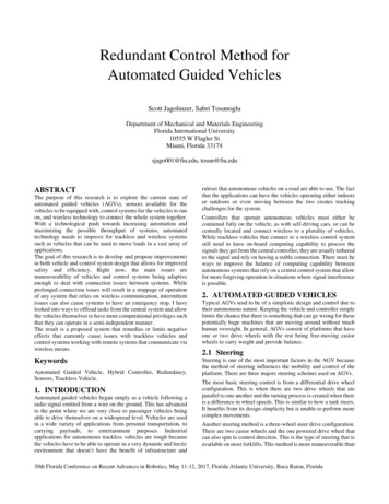
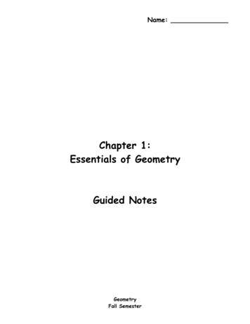
RollersControlPanelTrolleyRackIndicatorLightsMotor forRollersControlBoxBatteriesAGVFigure No.3.13: Image of completed Trolley assembled with AGV, Control box,batteries and motors.20
Chapter 4Test and ResultsThe assembled AGV mounted to trolley was subject to test in the factory floor on a modeltrack. The track was laid using black and white reflective tape with one bend to simulate allthe possible events in the actual factory floor. Figure 4.1 shows a comparison between theexpected actual factory floor and the model track.Storage Rack for one partabFigure No 4.1: a) Expected actual route for AGV, b) Test route layout for AGV.Figure No 4.2: Image of Test Route layout at factory floor.21
The AGV mounted trolley was tested for all the possible outcomes at the factory floor. Atoolbox was used as a substitute for the machined part. The various tests performed are: Manual Mode – Part intake and output Manual Mode – AGV free run Automatic mode – Rack Selection Automatic mode – AGV navigation, rack detection, part delivery and returnto home4.1Manual Mode – Part Intake and OutputThe system was switched to manual mode and the ‘Roller In/Out button’, which is atoggled push button, was used to verify the intake and delivery of parts. The systemworked fine in this mode. Figure 4.3 below shows the operation in progress.Figure No 4.3: Control Panel. Switches from left to right: 1-Start/Stop, 2Auto/Manual, 3-Part in/ Part Out, 4-Rack Select, 5-Emergency Stop.Figure No 4.4: Manual Mode - Part intake in progress: Part moves in from right toleft.22
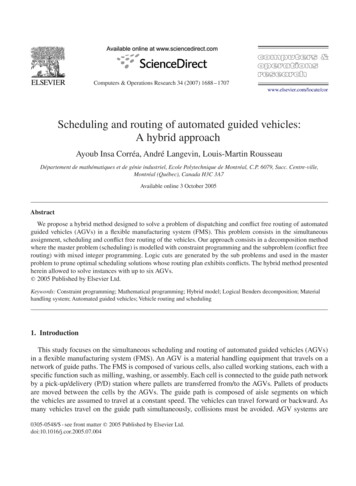
Figure No 4.5: Manual Mode - Part Output in progress: Part moves in from left toright.4.2Manual Mode – AGV free runThis mode was incorporated into the program to test the navigation capabilities of theAGV. It was used to determine the smooth movement along the track and how efficiently ittakes turns. It was evident that the navigation was satisfactory although a set of 5 sensorsinstead of 3 could have made it much smoother. The test also revealed that the AGV wascapable of taking turns around corners along the route effectively in both directions.However, mechanical constraints were noted with one of the wheels of the trolley brushingagainst the wheels of the AGV limited the degree of rotation of the AGV to the right. Thisdid not have much adverse effects on the maneuvering of the system, hence it was ignored.Following figures show the system in operation at the manual free run mode.Figure No 4.6: AGV taking a left turn in the free run mode.23
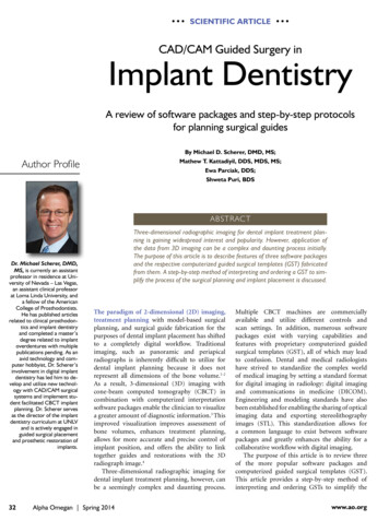
4.3Automatic mode – Rack SelectionThe system was then tested in automatic mode to simulate the selection of racks. Theselected rack is indicated by lamps on the control box. Each selected rack is indicated byits own lamp. Figure No 4.7 below shows images of the results of this test.abcFigure No 4.7: a) Rack one selected – Indicated by yellow lamp, b) Rack two selected– Indicated be green lamp, c) Rack three selected – Indicated by red lamp.4.4Automatic mode – AGV navigation, rack detection, part delivery and return tohomeOnce the part was in taken and the delivery rack selected (assuming total number of racksavailable is 3), the AGV was set to start to test whether the process took place smoothly.The AGV was supposed to reach the selected rack, deliver the part and return home. Asexpected, the AGV followed the route to the relevant rack, de
2.3 Automatic Guided Vehicle . Automated Guided Vehicles are battery-powered, unmanned vehicles that can be programmed to select paths and positioning. They can be utilized in fully automated control systems making them ideal for material handling in job shop environments where there is a fluctuating transport (Bilge & Tanchoco, 1997).