Transcription
Development of an Automated Guided Vehicle Prototype forMaterial Handling in an Aeronautic EnvironmentMarcos Llorente Hernándezmllorenteh@gmail.comInstituto Superior Técnico, Universidade de Lisboa, PortugalJuly 2020AbstractThis project intends to be focused on the prototype development of an Automated GuidedVehicle (AGV) to be introduced within the components shop at TAP Maintenance and Engineering. This autonomous vehicle will perform the material handling task along the shop,currently done manually, towing the cart that transports the pieces following a magnetic tape.The construction is made following the preliminary research and design done in theprevious years. Firstly, the cart is built according to the design and different modifications areexplored to make the coupling between cart and stands work correctly. In addition to this, thedesign of the group stands is also addressed. Next, the movement and control script of theAGV is developed using MicroBasic Lenguage. This code is, in turn, simulated with a softwareto verify the correct and safe operation of the vehicle.In terms of hardware, the interface and connections among all the electric components isapproached as well as the laser sensor configuration. The towing pins device that allows theattachment of the cart to the AGV is designed using electric lineal actuators. Moreover, thedesign of a two drive wheels configuration is explored as an alternative to the steerable wheelconfiguration initially selected.Finally, the battery charging system is selected after comparing the different chargingmethods. The advantages and disadvantages of each one are brought face to face and thedecision is taken based on several factors with different relevance for this application.Keywords: AGV, Material handling, Prototype development, Movement and control script,Battery charging system1Introductionstrategies that allow this, and here it is wherethe continuous improvement philosophy plays acrucial role.In the manufacturing and maintenance frame itis important to optimize the processes to get thefinal product with the best quality not penalizingthe costs and time involved, which implies beingcompetitive and improving the market share.The customer wants it cheap and good and thecompany has to do efforts to be able to offer thefinal product in time with a competitive price andtop quality. Thus, it seems essential to adoptOne of the most important tasks in this framework is the material handling, which has hugeinfluence on the production process and potentialprofits. Material handling is a remarkable sourceof wastes. For many decades the handling operations has been done manually with workerscarrying or driving vehicles transporting the mate1
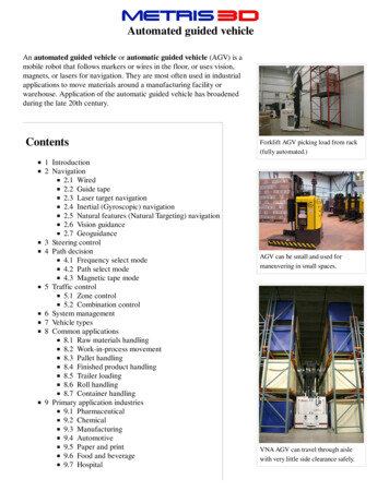
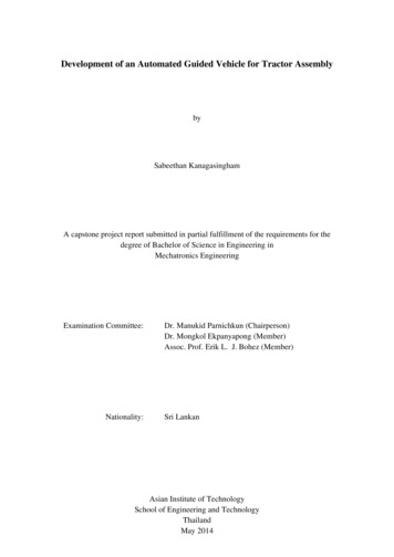
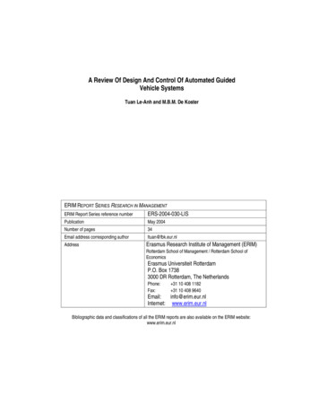
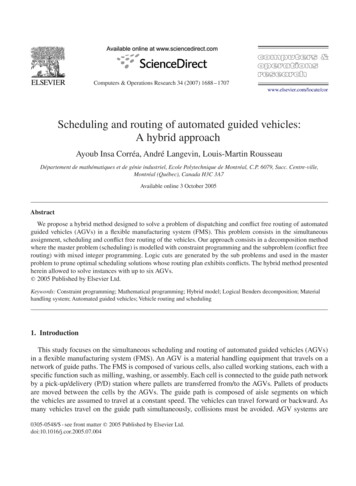
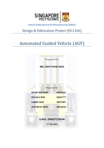
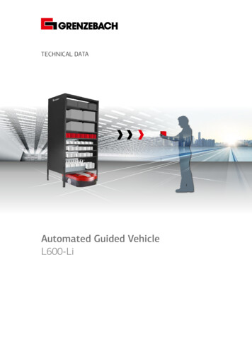
2rial. Nowadays a lot of companies have decidedto implement autonomous guided vehicles, bestknown as AGV to make this tasks without the needof relying in humans. An automated guided vehicleis a mobile robot that follows a path describedby markers or wires on the floor, or it uses visioncameras, magnets, radio waves or lasers fornavigation. The benefits are unquestionable sinceit reduces the labor costs in terms of salaries andtaxes, increases safety and gives the possibility ofworking in hazardous environments for the human.Moreover the AGV does not need to respect workshifts since it does not get tired and distractedwhich implies a reduction in the number of errorscommitted. They are mostly used in industrialapplications that required the material handling aswell as in hospitals to transport medicines, foodand bed linen [1].Material distribution systemTo get started, the efforts have been focused onthe construction of the cart and the receptionstations based on the design done in [3]. Unfortunately, the locking system is tested simulating acontact and it did not open unless a strong force isapplied forcing it. The TE connectors responsibleof providing relative movement between the tubesforming a ”T” are not ideal since there is not apure rotation around one axis but an additionalnot wanted tilt around the other two axis, directconsequence of the momentum produced by thecontact force which is misaligned from the tubewhere the TE connector is placed. This tilt blocksand complicates the natural rotation around themain axis, thus the locking system gets pluggedwhile trying to open (see Figure 1).The final objective of this project is to builda prototype of an AGV meant to work on theHP component shop at TAP M&E based on apreliminary design done in the two previous yearsby other students. The AGV introduces itself underthe cart where the pieces are transported, and itactivates two pins that allow to tow the cart. Ina first iteration, what it is wanted to achieve is tostart up the AGV following a closed path to do thedistribution of the different pieces to be repaired in4 different groups (Pneumatic, Hydraulic, Electricaland Fuel components). The AGV should makethe reception and expedition operations in anautonomous way following a magnetic tape placeon the floor and guaranteeing the safety of all theworkers every time at the shop.Figure 1: Scheme of the locking system apertureproblem. The red crosses represent the block inthe TE connectors rotation axisOnce it is known that the designed locking system does not work as it was suppose to, the searchof an alternative seems obligatory. Several alternatives have been tested in a trial and error process before coming up with the final idea. All thefailed solutions as the original one meant to keepthe multi-usage of the cart in all the groups. Selecting the position of the adjustable roller, eachcart shelf could be used for every group station giving to the cart the possibility of eventually carryingtrays to one single group using all the shelves forthat group. Unfortunately, it was not possible tofind a solution that solve the problem of the lockingsystem blockage, therefore it was decided, for thesake of the project feasibility, to change the concept and assign each of the cart shelves to onespecific group. Now the four cart shelves have different heights (see Figure 2 and Figure 3).The difference of level between the two uppershelves (same for the two lower ones) is established in 95 mm to avoid the activation of theshelves stoppers in wrong groups. The stationramp passes just above the stopper of the group2 cart shelf avoiding any contact. The samehappens when a tray is delivered to group 3. Inaddition, during the group 2 and 4 deliveries theactivation ramp will make a slight contact withTherefore, in order to reach this objective itwill be necessary to build both the reception andexpedition stands and the vehicle itself, which inturn consists in a cart that carries the trays withthe parts and the AGV towing it. All this elementshave been already designed but not tested, thusthe prototype will be constructed following thepreliminary design and testing if it works or not,making modifications of the design on the go asneeded. The structure and mechanisms of thestands and the vehicle are built using the TechnoLean materials available on the shop providedby Quimilock, which is the main supplier [2].In terms of safety, the AGV must be able torecognise obstacles that could eventually appear inthe middle of the path and stop, avoiding crashinginto them. Furthermore it must count with an emergency stop button to shut down the AGV whenever an emergency occurs and stop automaticallyin case of sensor failure.2
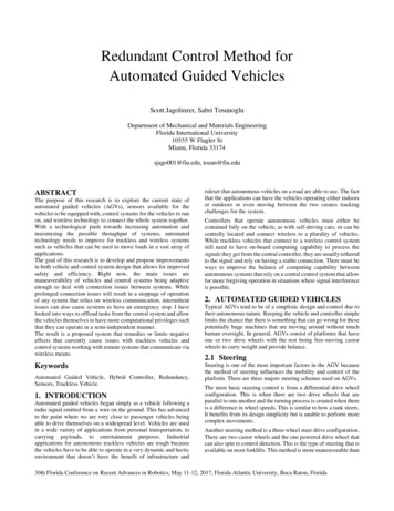
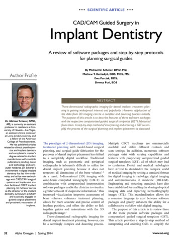
ones.The group 3 reception stand is exactly like thegroup 1 stand and the group 4 equal to the group2 stand but of course with different height given bythe correspondent cart shelf level.Figure 2: Cart shelvesFigure 4: Scheme of the reception process ingroup 1 (Top view)Figure 3: Scheme of a tray delivery to group 1group 1 and 3 cart stoppers partially openingthem but this shelves will be already empty. Thestation activation ramp consists in a TechnoLeanTD connector that stands out making contactwith the cart shelf stopper. Since the contact isproduced in the stopper tube itself the problem ofthe momentum disappear and the TE connectordoes not tilt not getting stuck.Regarding to the reception station, it was important to design a stand that allows to receiveand keep several trays waiting to be picked up andrepaired. Sometimes when a tray is placed in thereception stand, immediately a worker picks upthe tray to repair the pieces. However, especiallyin some groups, more often than not, the traysremain a certain time in the station awaiting to betaken. Since the cart will always make the trayexchange in the same shelf, in order to guaranteethat several trays fit in the stand it is necessary thateach delivered tray moves automatically followinga series of inclined multi-directional rollers railsoccupying the empty spaces of the station shelvessurface.Figure 5: Scheme of the reception process ingroup 2 (Top view)3AGV developmentThe AGV moves following a closed path that startsand ends in the reception and expedition areaand it goes across the shop performing the reception and expedition operations on each of the fourgroups. The navigation system is magnetic tapeguidance. The sensor mounted on the AGV detects the presence of the magnetic tape and this information is processed in the motor controller that,To understand better this design, schematic according to the programming script implementedpictures of the delivery process between the cart on it, sends steering commands to the wheels. Forand the stations 1 and 2 are presented in Figure 4 this application, it has been decided to connect theand Figure 5 respectively. The change of direction sensor MGS1600GY to a FBL2360 dual channelof movement in 90o is possible thanks to the motor controller, both by Roboteq company. All thegravity, the trays fall by its own weight and start to computation is done in the motor controller usingfollow a series of rails perpendicular to the initial the MicroBasic scripting language [4].3
3.1AGV script developmentthe obstacle is detected into the protection field theAGV must stop immediately and wait for the blockage clearance. Once this happens, it resumes thewalk after a few seconds (”ResumeTime”). On theother hand, whenever a sensor stops working theAGV immediately stops.The code is developed in a way that allows theAGV to follow the magnetic tape and stop oneach station for a brief time to perform the traysdelivery or pick up besides going and stopping atthe charging station when the battery is low. Inorder to make the AGV stop in the different groupstations two magnetic markers will be placed onboth sides of the path being the right one ahead.When the sensor detects that both markers arepresent, the AGV stops and it starts the countdownto resume the motion. During this brief pause timethe trays are exchanged between the AGV cartshelf and the group stand.The AGV tows the cart that transports the trayswith the aid of towing pins. They are retractedwhen the AGV stops in the base and deployedagain when a new route is started after pushingthe ”Go Button”. They keep deployed until the AGVreturns to base. There is a time delay (”PinsTime”)between pressing the button and starting themovement to make sure that the pins have enoughtime to deploy before the AGV starts walking. Thepins mechanisms consist in a pair of electric linearactuators connected both to digital outputs 1 and2 of the motor controller.To identify the Base position, where the AGVis meant to start all the routes, and the BatteryCharging Station, both in the Reception / Expedition room, it is necessary to place the markers ina special way, different from the one used for thestations stops. It has been decided to place anunique left marker and short right markers separated, forming a dashed line (Figure 6)Finally, concerning the control of the AGV ithas been tested two ways of control (Proportionalcontrol and PID). The sensor outputs a valuethat is the tape’s distance from the center of thetrack. This information is then used to correctthe steering. The further the track is from thecenter, the stronger the steering change. For thisapplication, since the path is simple to follow anddoes not contain any sharp or consecutive curves,and the AGV will move at low speed, it is expectedthat the proportional control is enough to have asatisfactory control. However, this will be verifiedin the test as well as the control parameters tuning.Figure 6: Group station (left), Base position (middle) and Charging station (right) markersThe code is build in a way that allows to counthow many right markers there are and thus identifywhether the AGV is at the Base position or atthe Charging Station. When the AGV has fullycharged the batteries in the charging station, itautomatically returns to the base position. Thebattery charge status is known monitoring thebattery voltage.In order to check whether the code architecturemakes the AGV perform the desired task, the scriptis simulated in a free AGV simulator software provided by Roboteq [5]. This simulator gives the possibility of sketching the path, place magnetic markers wherever necessary and configure the AGVcharacteristics.Whenever the AGV approaches to a fork ormerge it will take the left or the right path depending on whether the last marker detected was onthe left or right side. Nevertheless, in functionof the type of operation, the AGV must follow adifferent path whether it is performing a receptionor an expedition operation. Therefore, in the twopoints where the path is split for each one of theoperations it is necessary to place a marker similarto the ones in the Charging Station and Base butthis time with only two right markers.3.2AGV buildingThe different electrical components that define theAGV are presented in Figure 7 and the generalview of the AGV structure with the main components is shown in Figure 8.However, it is also explored the possibility ofusing a two drive wheel configuration instead asingle steerable drive wheel configuration. It isconsidered that the most suitable option would bethe use of the Benevelli DD1 Serie [6] becauseits diameter is similar to the steerable drive wheeland it consists in a complete assembly of the twowheels unlike other considered models.In terms of safety, the AGV must comply withsome requirements like stopping when an obstacleis detected by the laser sensor or any sensor fails.There are two kind of fields detected by the lasersensor, the warning field and the protection field.Whenever an object is detected in the warningfield the AGV must emit an alert sound, however if4
Figure 9: AGV 3D model steerable drive wheel attachmentFigure 7: AGV electric componentsIn case of changing the single steerable drivewheel to the 2 drive wheels configuration somemodification must be done in the front part of thestructure. The length is increased and the widthdecreased to align the support tubes with thewheels holes allowing the fastening of the wheelsassembly to the structure through M8 screws. Thisnew AGV structure is meant to fit the BenevelliDD1 series drive wheel, nevertheless, it could alsobe used to attach the other wheels models makingheight adjustments of the support tubes as wellas modifying the width and length of the front partstructure as necessary. The design of the AGVchassis for the 2 wheels configuration is presentedin Figure 10.Figure 8: AGV electric componentsThe laser range finder sensor is configured withthe SICK Configuration and Diagnostic Software(CDS) downloaded in the manufacturer website[7]. The main feature of this software is that itallows to customize the dimensions and shapeof both, the warning and protection fields of thesensor. In this way, whenever an object entersin any of the zones, the output signal (OSSD)is switched and sent to the controller connectedto the sensor. If the obstacle is detected in thewarning zone, the AGV will emit an alert sound,and if the blockage is found within the protectionzone, the AGV stops immediately until the obstacleis removed.Figure 10: Two drive wheels configuration, AGV 3Dmodel perspective view4Regarding the structure of the AGV, it is designed to support all the electric and mechanicalcomponents as well as offering a correct couplingwith the cart. Again, it is completely built usingTechnoLean materials which provides a wideflexibility to do modifications easily if necessary.Charging systemThe charging methods for AGV batteries can beclassified essentially in two types, contact andcontactless. The contact charging methods, asits name indicate, works making direct contactbetween the battery terminals and the charger.For AGV applications, these systems are typicallycompounded of two parts. A base plate placedoutside of the AGV fixed generally to the floor orany lateral support and connected to the batterycharger, and a current collector which is mountedThe steerable drive wheel is easily fixed to thestructure through four screws M10 that pierce thetubes located just above the wheel attaching thewheel to them as shown in Figure 9.5
in the AGV connected to the battery terminals.When the collector makes physical contact withthe plate, the current passes from the charger tothe batteries.The contactless charging makes use of themagnetic induction to charge the batteries notrequiring physical contact between the batteryterminals and the charger. The system consistsin a transmitting unit and a receiving unit. Thetransmitter is connected to the AC electrical gridand contains a coil that generates a magneticfield when the AC current passes through it. Next,this magnetic field induces an AC current in thecoil contained in the receiver existing an air gapbetween both coils. This AC current is convertedto DC by a rectifier and smoothing circuit andregulated before supplying the batteries.Figure 11: Roboteq Robopads [10]around the perpendicular axis of the support structure, it can be added a 90x64x3 mm metallic plateused as joint between the two parallel tubes thatsupport the collector through four M4 screws.It also exists an advanced wireless charging technique called magnetic resonance, thateven though it is based exactly on the sameprinciple than the latter, it increases the alignment flexibility avoiding the severe efficiency dropfor larger gaps and misalignment between coils [8].To decide which method is the most suitable,it will be taken into account 4 factors (efficiency,alignment/ air gap flexibility, costs and maintenance). Next, it is assigned a specific weight toeach factor in function of its relevance. After allthese, it turns out that the best charging methodsfor this application is the contact charging becauseit presents the highest efficiency, a moderatealignment flexibility, the lowest cost and it does notrequire a constant maintenance effort due to thehigh resistance to friction wear of the plates, andsweeper accessory that can be attached to thecollector to keep the ground plate cleaned, free ofdust and particles each time the AGV pass overthe charging station.Figure 12: AGV Bottom view detailThe model selected is the Roboteq Robopadcharging system that uses magnetic contacts tomake contact instead of conventional spring contacts (Figure 11). This increases the number ofcycles that the charging device lasts due to the reduction of accumulated friction wear [9].The attachment of the collector to the bottom ofthe AGV chassis is done through four M4 screws,however some modifications of the structure mustbe done to fix the collector. The design is presented in Figures 12 and 13 for the steerable drivewheel configuration. For the two drive wheels configuration the design of the attachment structurewould be similar adapting the tubes dimensions.Note that in order to avoid any possible rotation6
presenting the highest efficiency besidesenough alignment flexibility and not requiringa periodical maintenance.It is also thecheaper and simpler option.ReferencesFigure 13: AGV Perspective detail5[1]M. Fierro. (2020). Agv concept, [Online].Available: https : / / prezi . com /6s6eypmwtidd/the- history- of-the-agv/(visited on 03/18/2020).[2]Quimilock. (2020). Technolean catalogue,[Online]. Available: https : / / www .technolean . com / wp - content / uploads /2018 / 12 / 181212 Technolean CatalogoESP-web.pdf (visited on 03/24/2020).[3]M. Cheira, Design of an Automated GuidedVehicle for material handling. Master Thesis.Instituto Superior Técnico, 2019.[4]ROBOTEQ. (2020). Roboteq microbasicscript manual, [Online]. Available: https://www . roboteq . com / index . php / docman /motor - controllers - documents - and files/documentation/user- manual/650microbasic- scripting- manual/file (visited on 04/19/2020).[5]Roboteq. (2020). Roboteq agv simulatorsoftware, [Online]. Available: https : / /www . roboteq . com / index . php / support /downloads (visited on 04/19/2020).[6]BENEVELLI. (2020). Benevelli drive wheels,[Online]. Available: https : / / www .benevelli - group . com / index . php / 2 uncategorised / 31 - electric - drive wheels (visited on 05/13/2020).[7]SICK. (2020). Cds software, [Online]. Available: https://www.sick.com/es/es/cds/p/p37940 (visited on 05/02/2020).[8](2016). Inductive versus resonant wirelesscharging: A truce may be a designer’s bestchoice, [Online]. Available: https : / / www .digikey . com / en / articles / inductive versus-resonant-wireless-charging (visited on 05/19/2020).[9]Roboteq. (2020). Robopad, magnetically activated charger contacts for mobile robots,[Online]. Available: https://www.roboteq.com / docman - list / motor - controllers documents - and - files / documentation /datasheets/911- robopads- datasheet- 1/file (visited on 05/22/2020).Conclusions The first design of the cart did not offered acorrect functionality in terms of coupling between cart and group stand causing problemsin the opening of the stoppers mechanism thatallows the trays exchange. Therefore, aftertesting several concepts and solutions, a simpler stopper mechanism was implemented requiring that each one of the four shelves wasassigned unequivocally to one group. The design of the reception group stands hasbeen carried out in a way that makes themcapable of storing several trays. The script that commands all the movementand control of the AGV has been written using MicroBasic language and simulated. Sincethe simulator does not allow to configure theAGV with only one steerable drive wheel, theresults of the simulation are valid in terms ofmovements and task performances, but not interms of steering control. In order to get a better match up between the simulations outputsand the real life, it is also proposed the use of anew AGV configuration consisting in two driverwheels instead of one which can be perfectlyset in the software. The towing pins device consists in two electriclineal actuators connected to two simplerelays that allow the inversion of the motorspolarity in function of which one of the twodigital outputs is active. The rod of the actuator is deployed whenever the AGV is runningallowing the cart towing, and retracted whenthe AGV is stopped in the base. The contact charging method has beenselected above the magnetic induction andmagnetic resonance methods because of7
[10]ROBOTEQ. (2020). Robopads charge system, [Online]. Available: https : / / www .roboteq . com / all - products / robopads charge-system (visited on 05/18/2020).8
to implement autonomous guided vehicles, best known as AGV to make this tasks without the need of relying in humans. An automated guided vehicle is a mobile robot that follows a path described by markers or wires on the floor, or it uses vision cameras, magnets, radio waves or lasers for navigation. The benefits are unquestionable since