Transcription
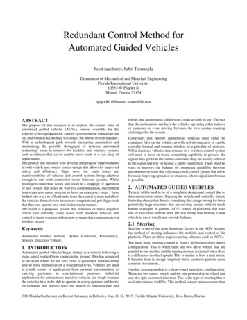
Redundant Control Method forAutomated Guided VehiclesScott Jagolinzer, Sabri TosunogluDepartment of Mechanical and Materials EngineeringFlorida International University10555 W Flagler StMiami, Florida 33174sjago001@fiu.edu, tosun@fiu.eduABSTRACTThe purpose of this research is to explore the current state ofautomated guided vehicles (AGVs), sensors available for thevehicles to be equipped with, control systems for the vehicles to runon, and wireless technology to connect the whole system together.With a technological push towards increasing automation andmaximizing the possible throughput of systems, automatedtechnology needs to improve for trackless and wireless systemssuch as vehicles that can be used to move loads in a vast array ofapplications.The goal of this research is to develop and propose improvementsin both vehicle and control system design that allows for improvedsafety and efficiency. Right now, the main issues aremaneuverability of vehicles and control systems being adaptiveenough to deal with connection issues between systems. Whileprolonged connection issues will result in a stoppage of operationof any system that relies on wireless communication, intermittentissues can also cause systems to have an emergency stop. I havelooked into ways to offload tasks from the central system and allowthe vehicles themselves to have more computational privileges suchthat they can operate in a semi-independent manner.The result is a proposed system that remedies or limits negativeeffects that currently cause issues with trackless vehicles andcontrol systems working with remote systems that communicate viawireless means.KeywordsAutomated Guided Vehicle, Hybrid Controller, Redundancy,Sensors, Trackless Vehicle.1. INTRODUCTIONAutomated guided vehicles began simply as a vehicle following aradio signal emitted from a wire on the ground. This has advancedto the point where we are very close to passenger vehicles beingable to drive themselves on a widespread level. Vehicles are usedin a wide variety of applications from personal transportation, tocarrying payloads, to entertainment purposes. Industrialapplications for autonomous trackless vehicles are tough becausethe vehicles have to be able to operate in a very dynamic and hecticenvironment that doesn’t have the benefit of infrastructure andruleset that autonomous vehicles on a road are able to use. The factthat the applications can have the vehicles operating either indoorsor outdoors or even moving between the two creates trackingchallenges for the system.Controllers that operate autonomous vehicles must either becontained fully on the vehicle, as with self-driving cars, or can becentrally located and connect wireless to a plurality of vehicles.While trackless vehicles that connect to a wireless control systemstill need to have on-board computing capability to process thesignals they get from the central controller, they are usually tetheredto the signal and rely on having a stable connection. There must beways to improve the balance of computing capability betweenautonomous systems that rely on a central control system that allowfor more forgiving operation in situations where signal interferenceis possible.2. AUTOMATED GUIDED VEHICLESTypical AGVs tend to be of a simplistic design and control due totheir autonomous nature. Keeping the vehicle and controller simplelimits the chance that there is something that can go wrong for thesepotentially huge machines that are moving around without muchhuman oversight. In general, AGVs consist of platforms that haveone or two drive wheels with the rest being free-moving castorwheels to carry weight and provide balance.2.1 SteeringSteering is one of the most important factors in the AGV becausethe method of steering influences the mobility and control of theplatform. There are three majors steering schemes used on AGVs.The most basic steering control is from a differential drive wheelconfiguration. This is when there are two drive wheels that areparallel to one another and the turning process is created when thereis a difference in wheel speeds. This is similar to how a tank steers.It benefits from its design simplicity but is unable to perform morecomplex movements.Another steering method is a three-wheel steer drive configuration.There are two castor wheels and the one powered drive wheel thatcan also spin to control direction. This is the type of steering that isavailable on most forklifts. This method is more maneuverable than30th Florida Conference on Recent Advances in Robotics, May 11-12, 2017, Florida Atlantic University, Boca Raton, Florida
differential steering and can perform smooth and accurate motionsbut still isn’t the most maneuverable option.The third option is a two steer-drive wheel configuration. Thisconfiguration has two drive wheels that can be rotated and twocastor wheels. This steering configuration allows from the vehicleto move in any direction and turn on the spot. Similar to the 2 steerdrive wheel configuration is the Quad wheel configuration. Thiscombines two fully rotatable drive wheels with two castor wheelsto give the best range of motion and highest maneuverability [37].A possible improvement that will be explored is having four drivemotors that can all be rotated independently. This has the advantageover the two steer-drive configurations in that all four wheels aredriven, allowing for double the available power and can also allowfor power efficiency and reliability by disengaging a pair of wheelsto drop the power consumption by half or allow for continuedoperation if a motor for a wheel breaks or a sensor malfunctions.This fault-tolerance system will allow for increased efficiency andreliability.2.2 Vehicle DesignA more robust control system for an AGV requires a more robustvehicle. The design of this vehicle allows for size scalability andmaneuverability for a wide array of uses. The vehicle has a verysimple design consisting of 3 main parts.Figure 1. Wheel mounting bracket showing rotational gearinterface and space for linear motor mountingFirst is the wheel and mounting bracket. This consists of the wheel,the bracket that the wheel is mounted to, and the drive motor forthe wheel. Since the wheels are meant to spin a full 360 degrees thebracket must be able to easily rotate with respect to the mainplatform while also being able to stably support the loading of thevehicle. To account for both these needs, the cuff of the bracket hasa wide plate on the top and bottom that help distribute the loadingfor each wheel assembly while also limiting the frictional forcesthat need to be overcome for rotation of the cuff to be performed.Figure 1 shows an earlier design of the wheel and cuff. As can beseen midway up the bracket, there is a gear built into it. This is forthe second motor to interface with to control the wheel orientation.In figure 1 the placement of the drive motor is shown on the outsideof the bracket lined up with the axis of the wheel. The bracket caneither have one motor mounted to one of the sides, or two motorsworking in tandem mounted on both sides to amplify the poweravailable to the wheels while keeping the size of the motors incheck.the required mechanics for the vehicle such as power source(batteries or generator), the motors that control wheel orientation,most of the onboard sensors, and the computer system.Figure 2. Underside of platform showing a possible wheelconfiguration with respect to the center of the vehicleTo make control of the wheels as simple as possible, they are laidout along a circular pattern with respect to the center of the vehicle.By having the wheels laid out in a circular pattern about the centerof the vehicle, it creates an easy reference not only between thecentral point of the vehicle, where the position will be taken from,but also an easy reference between wheels so that rotationalmaneuvers have the most evenly distributed output requirements.This layout allows for the required wheel velocities andorientations to be easily calculated getting eight outputs (velocityand orientation of each wheel) from three desired inputs (linervelocity, direction, and vehicle orientation). Knowing only thelength and width of the wheelbase, the location of all four wheelscan be resolved for the system to properly calculate the requiredmotor outputs to the wheels.Since each wheel is independently controller that mean each wheelhas two motors, one each for linear and rotational velocity outputs.Each wheel system is connected to the main platform via a cuff thatis designed to be able to carry the required loadings for the vehiclesdesired application. The rotational motor is mounted within theplatform and interfaces with the wheel system via a gear. The trickypart comes with the mounting location of the drive motor. Thereare two options, on the platform or directly to the wheel mountingbracket. Mounting from the platform would require a driveshaftthat can not only operate at an angle, but be able to compensate forthe rotational movements with the vehicle without affecting wheelvelocity. Mounting from the wheel bracket gives an easy, directconnection to the wheel but creates an issue with wiring back to theplatform to be able to receive power and a signal. Mounting to thewheel bracket was determined to be preferable since slide contactscan be used for the transfer of power and required data.Figure 3 shows how given a desired linear (red arrow) androtational (blue arrow) velocity for the vehicle as a whole, it can bebroken down to the wheel components which combine for the totaloutput for each wheel (green arrow). Notice how the blue arrowsfor each wheel are always tangent to the circle that the wheels alllie on. The resultant motion shown is of the vehicle driving in astraight line while its orientation is rotating counter-clockwise.Second is the lower platform. This is the main housing for thevehicle as it is where the wheel brackets link into as well as housing30th Florida Conference on Recent Advances in Robotics, May 11-12, 2017, Florida Atlantic University, Boca Raton, Florida
Figure 6. Compete vehicle with upper platform that isdesigned to handle large shipping containersFigure 3. Desired linear and rotational velocity depicted in thecenter result in the wheel outputs (green, with red (linear) andblue (rotational) componentsFigure 4 shows a design for the lower platform where there arelarge recessed areas for the wheel bracket to slot into along withribbing along the platform to reinforce it in areas where forces areexpected to be transferred along the body of the vehicle. Thepositional sensors can also be seen mounted at each of the cornersof the vehicle. Having a sensor on each corner allows for anenvironmental sensor to be able to see at least two of the vehiclesensors at a time assuming no other obstacles possibly blocking theline of sight besides the cargo onboard. Figure 5 shows the samelower platform with the wheels in place. The top of the bracket cuffis flush with the platform ribbing and the built-in gear are exposedbelow the platform. This allows for the orientation motors to bemounted to the lower platform and have them connect to the wheelbrackets via a hole in the floor of the platform.Figure 4. Lower platform complete with cutouts for wheelbrackets and positional sensors mounted to cornersFigure 5. Lower platform with wheels in placeThird is the upper platform. The upper platform sits on top thelower platform covering and protecting the mechanical componentsof the vehicle while also providing the required base to interfacewith the desired cargo be it pallets, shipping containers, or people.The upper platform can be designed with a specific requirement inmind. Figure 6 shows an upper platform that is designed to hold a20x8 foot cargo container. The modular design allows for the upperplatforms to be interchangeable with the main vehicle allowing forone vehicle to be used with many types of cargo without having tocompromise on how the cargo interfaces with the vehicle.3. SENSORS3.1 Guidance MethodsThere are various methods for guiding the vehicles. These includewired navigation, guide tape, laser target navigation, inertialnavigation, natural feature navigation, vision guidance, or geoguidance.Wired navigation is simply a wire carrying a radio signal embeddedinto the path the AGV is to traverse. The AGV has a sensormounted below it that hovers just off the surface and picks up thesignal from the wire, which allows for the vehicle to sense andfollow the wire.Guide tape is similar in principle to the guide wire but the guidetape carries no signal. Instead either a colored or magnetic tape isplaced along the desired path and either a vision system or magneticsensor read and follow the path laid out by the tape. There areadvantages and disadvantages to both visible and magnetic tape.Visible tape, while it is cheap to install and make path adjustments,since it needs to be on the surface of the path to be viewed by theAGV, it can be damaged or dirty through daily vehicle andpersonnel activity. A system that uses a visible guideline forsteering control has two ways it handles the guideline to control thesteering. The first way, when the vehicle is moving at a slowerspeed it reacts to the error values of the vehicle with respect to theline. When moving faster, the controller uses the slope of the lineto determine the required steering as waiting for error results couldcause the vehicle to not be able to react in time at higher speeds. [J.Lee] The magnetic tape allows for it to be embedded into the pathand therefore is not exposed to wear. However, having to carve outa channel and cover the buried magnetic tape results in a costlierinstall and makes it harder to change the path layout.Laser target navigation uses a rotating laser emitter and sensor intandem for distance detection that can be used for position tracking.The laser is reflected off reflective tags that are affixed to walls,poles, or other fixed obstacles, each of which corresponds to aknown point in the workspace by the system. Therefore, byreflecting off the various reflective tags, the vehicle can triangulateits position and use that knowledge to plan and execute its motionbased on the data that is collected and processed in real time. Thereare two types of laser sensors, modulated and pulsed. Modulatedlasers have a larger range and higher accuracy over a pulsed laserwith an angular resolution of 0.006 . Pulsed lasers have an angularresolution of 0.2 and must be interpolated by the intensity of thereflection at each data point to reliably get an accurate location. Forthe system to work the vehicle needs to be in view of at least 3environmental reflectors to correctly triangulate its position [38].Inertial navigation uses a gyroscope that can, within an inch, detectthe movement of the vehicle. It also uses transponders located inthe workspace floor to verify the position of the vehicle. This30th Florida Conference on Recent Advances in Robotics, May 11-12, 2017, Florida Atlantic University, Boca Raton, Florida
system is flexible in that it can be used in a wide range ofenvironments with or without the feedback [39].Natural feature navigation uses range detecting sensors inconjunction with gyroscopes to read the layout around it and thevehicle triangulates its position using the natural features on theenvironment. It uses the data of its surrounding to develop theshortest possible distance to its destination since the system doesn’tnecessarily know the layout of its surroundings [39].If the natural feature navigation did have full knowledge of itssurroundings, then this system would be considered a geo-guidancesystem as it operates in the same way a laser guidance system worksbut without the reflective tags.Vision guidance uses cameras to view their surroundings in a full3D image and then builds a 3D map of the workspace. It can thenmatch up its live view with that of its 3D map to be able todetermine where it is in the workspace. It can also be programmedto recognize certain features such as obstacles or humans as toallow for the vehicle to stop or reroute [19].3.2 Proposed Sensors for Control MethodThe sensors that will be used on board and in the environment, willplay a large role in the capabilities of the system. While therobustness of the control scheme is the foundation for autonomouscontrol, an equally robust array of sensors is required to feedenough pertinent information that the system can make wellinformed decisions.Vision sensors are those that use the visible light spectrum tocapture an image for the system to process. Since a computercannot inherently look at a picture and understand what it isdisplaying like a human can, the controller needs to be programmedto identify pertinent information from the video feed it is receiving.This can be as simply as recognizing a colored line on the floor andknowing it should follow it to recognizing certain shapes such aswalls, other vehicles, or any other obstacles it could come acrossand knowing how to take evasive action. A vision system is veryflexible but requires extensive programming work to get the mostout of it [2].Magnetic sensors pick up on a magnetic field that is present. Amagnetic sensor can be used in the same way that the radio sensorwas used by reading the signal from a magnetically charged wirethat defines a path for the vehicle.Gyroscopic/force sensors can measure the forces that the AGV isexperiencing due to acceleration. This can be used to gauge andcontrol the acceleration and deceleration of the vehicle while alsomonitoring lateral forces that could be imparted by taking turnswith a moderate speed.Global Positioning Systems are another way to detect the positionof the vehicle and is especially useful in an outdoor workenvironment that is exposed to more variables such as weather andtime of day that can affect some of the sensors mentioned above.All the above sensors can be used together to give an automatedvehicle a plethora of instruments that allow for the vehicle to readand navigate its environment [25]. The sensors each have theirstrengths and weaknesses that must be considered when choosingthe right sensors to design a control system around. It is alsoimportant to have built in fail safes and redundancies into thesystem such that control will not be lost should a sensor go downor an environmental condition affect the system. One example is ifthe lights go out in the workspace and the controller only operatedoff of vision sensors. This would cause the system to lose all inputfrom the sensors. And while at that point one would hope that thecontroller is programmed to shut down in that scenario, there is amoment while all these vehicles would be trying to stop that theywould be blind and at risk for collision. In this scenario ultrasoundand infrared sensors can be used to protect against this situation.Infrared sensors are not impaired by the lack of light and useinfrared emitters placed n the environment to determine its position.Ultrasound sensors rely only on sound waves to detect theproximity of objects from it. This could allow for the vehicle todetect any objects that would be in its vicinity and allow for it tomaneuver in a way that it would be able to avoid the object althoughit is not able to ‘see’ it in the conventional sense.Ultrasonic sensors can typically be used as proximity sensors sinceit is very easy to time the bounce of the signal and determine thedistance of the object reflecting the sound waves. While thesesensors would not be used for controlling the vehicle, they areinstead used as a fallback safety system to warn and allow for thevehicle to stop if anything unexpected ever enters a predefinedworkspace of the vehicle. When dealing with large and expensivemachinery, especially machinery that is moving autonomously, itis important to have multiple sensing and safety layers [23].Infrared sensors can be used for tracking of the vehicle andpositional sensing. While similar to the vision system, since thesesensors only operate on the infrared wavelength, special infraredemitters and reflectors can be placed on the vehicles and in theenvironment to allow for positional data to be determined since theenvironmental emitters and sensors will always have a fixed andknown location [24].Radio frequency sensor picks up radio signals that are present. Inthe history of theFigure 7. Diagram of 3-D relative positioning sensor forindoor flying robots [14]AGV, this sensor has been used to allow the vehicle to read andfollow a wire that emits a radio frequency that is embedded into thefloor that defines the desired path of the vehicle.The infrared sensor and emitter clusters depicted in figure 7 weredeveloped for use on indoor flying robots [14]. However, the sensordesign can be used with an autonomous vehicle control system. Thedesign calls for a spherical array of infrared emitters and sensors.30th Florida Conference on Recent Advances in Robotics, May 11-12, 2017, Florida Atlantic University, Boca Raton, Florida
In the figure below the blue and red spheres depict themrespectively, however they are only depicted as two distinct objectsto clearly show the interaction between the emitting and sensingportions of two sensors. The actual sensor is a sphere with both theemitters and sensors interspersed between each other. This allowsfor each vehicle outfitted with the sensor to not only read itsenvironment but to also be able to be sensed by other vehicles andby sensors in the environment that monitor the positions of thevehicles.When the sensor picks up a signal, it measures the intensity of thatsignal at each of the sensor nodes. It uses the three strongest signalsand then triangulates the direction and uses the signal intensity todetermine the distance the object emitting the signal is from thesensing object. This can be done since the geometry of the sensorsphere is known and the decay of the infrared light intensity can beexperimentally found and then applied to calculating proximity.4. CONTROL METHODThe proposed control system is to use and build upon elements fromprevious control systems such that efficiency and reliability areincreased.A hybrid controller will be employed for the system having a maincontroller monitors all sensors, both environmental and those oneach vehicle, and control the fleet of vehicles on a macro level withpath planning and task queueing. Each vehicle will also beequipped with a controller able to read from its sensors and performon board calculations and take independent control of the vehiclewhen either contact with the main controller is temporarily lost orfor a reactionary maneuver that would take too long for the centralcontroller to sense and react to.The motivation for having multiple control layers for this system isto increase reliability of the system. With these vehicles beingtrackless, they are not hardwired into the control system and oftenrely on a Wi-Fi or other close ranged network signal that canfluctuate in coverage or suffer from slowdown when too muchinformation is being transmitted. If control was handled purelyfrom a central system, any network interference would cause anaffected vehicle to stop and wait for either the signal to return orfor a manual override.The system will have a wide array of sensors, both onboard thevehicles and in the environment. The primary positioning sensorwill be the 3D spherical emitter and sensor arrays. Each vehicle willhave of these 3D sensors, on at each corner of the vehicle. This willallow for the sensors in the environment to be able to always havea clear view of at least one of the sensors regardless of vehicleorientation and allow for it to calculate the orientation of thevehicle. These sensors not only allow for the central system to readthe position of the vehicles, but also allow the vehicles to read theirposition in the environment and allow them to read other vehiclesthat they have line of sight with.The benefit of each 3D sensor is that it both emits and reads so thatthe information is always being shared both ways between thevarious systems. This allows both layers of the control system toindependently track position and verify the data between them andallow for them to operate independently should one end fail or losecontact.A GPS sensor could be used for each of the vehicles if theapplication has a large outdoor workspace where it would beuneconomical or impractical to cover the whole workspace withpositional sensors.The vehicle themselves are equipped with an accelerometer, loadscale, positional and velocity tracking for each of the vehicleswheels, proximity sensors, and cameras.The goal of the main system level controller is to be the managerof the entire system. It should be able to receive inputs from outsidethe system, such as user input for desired tasks, and then assign thatto an active vehicle in the fleet. In assigning the tasks, the systemneeds to consider the positions of all the vehicles and their taskstatus. It should assign new tasks as they come in such that it iscarried out in the most expedited manner without affecting the flowof the rest of the tasks. The main system also calculates the paththat the vehicle needs to take to carry out this task. The pathplanning is fully calculated before the task is assigned so that afterthe vehicle is assigned the task from the system, it could completethe task even if its connection with the main system is interrupted.While the task is being completed the two systems share all theirsensor data to cross reference for verification and to monitor theprogress of the vehicle.The vehicle level controller is a simpler system that just takes theassigned pathing data and convert that to the required outputs foreach of the four wheels. The vehicle controller also monitorsonboard sensors that are mostly to monitor the surroundings forpossible obstacles that would need to be avoided.With four independently powered and rotatable wheels there are alot of factors that go into the outputs for each of the wheels. Sincethey are not physically synchronized and are capable of beingoperated at different orientations, the precision of the controller isparamount since loss of wheel control when the vehicle velocity issufficiently perpendicular to the wheels can cause damage or abruptstops that could cause the load to be jolted loose. The two datapoints that are fed into the vehicles system are the desired Cartesianposition of the vehicle along with its desired orientation. Each ofthese can be calculated as separate components of the wheel outputsthen combined afterwards to get the independent signals for eachwheel. This simplifies the calculations since the component of thewheel output for positional data is the same for each of the wheels.The orientation component of the wheel output is in a directiontangent to a circle that is centered on the middle of the vehicle andpasses through each of the wheel’s locations. This output is affectedby the dimensions of the vehicle so it is very important that thoseare represented correctly in the system. Each of these componentsof the wheel output are linearly combined to give the requiredindependent outputs for the wheel velocities and headings.4.1 Positional DataHaving the vehicles use 3D relative positioning sensors they do notneed to rely on more conventional methods such as GPS or wheelencoders, which each have shortcomings, lack of precision in someenvironments and error accumulation respectively. The onlydownside to using the 3D relative positioning sensors (3DRPS) isthat you have to make sure that there are enough environmentalsensors within line of sight of the vehicle in its workspace. With thevehicles and environmental sensors having a broadcasting andreading sensors, each can determine the location independently andcross reference for accuracy.Each vehicle would be equipped with a minimum of two sensors inknown locations on the vehicle. The environmental sensors arelocated in known locations within the vehicle workspace.For the master system to determine the location of a vehicle itrequires that one environmental sensor reads two sensors on the30th Florida Conference on Recent Advances in Robotics, May 11-12, 2017, Florida Atlantic University, Boca Raton, Florida
vehicle to resolve the 2 unknowns of location and orientation. Ifmultiple environmental sensors can read the vehicle, then multiplereading can be cross referenced to improve reliability and reducethe possibility of a rogue reading or noise.The vehicles have two possible methods for determining itslocation and orientation. The first way to determine its location isby reading its distance from a known location of an environmentalsensor plus a compass reading (heading). The second method is tohave one of the vehicle sensors read the locations of twoenvironmental sensors.to time to control the velocity of the vehicle depending on loadssuch that it can safely stop given the range of its onboard sensors.Second, the controller monitors all the sensors that are hardwiredinto its system. These are all the environmental sensors so that thecontroller can make informed decisions on path planning andcurrent work flow. This can allow the system to read obstructionsso that it can plan ahead of time instead of having the vehicle itselfsense the obstruction and have to react locally.The above methods for determining the vehicles location are theminimum data points required and more can be used for verificationpurposes.4.2 System OutputsThe vehicle has a total of eight motors that work together to providethe desired vehicle movement. There are four drive motors (DM),one for each of the drive wheels which are controlled by setting adesired velocity. There are four rotational motors (RM), one foreach of the drive wheels that control the angular orientation of eachwheel indecently. They are c
Automated Guided Vehicle, Hybrid Controller, Redundancy, Sensors, Trackless Vehicle. 1. INTRODUCTION Automated guided vehicles began simply as a vehicle following a radio signal emitted from a wire on the ground. This has advanced to the point where we are very close to passenger vehicles being able to drive themselves on a widespread level.