Transcription
OLEDs VS. LEDs Organic LEDs and Their Feasibility inGeneral-Lighting ApplicationsVioLight - Improving Color Solais Lighting, LLC All rights reserved.1
For many years, (light-emitting diodes) struggled to fulfill their promise as the dominant technology for thenext generation of general-lighting. As the major LED manufacturers began to expand capacity (therebydriving down costs), many end users continued to complain about color quality, usable-life claims and theactual return on investment. Through this feedback, manufacturers realized that the requirements for thegeneral-lighting market were not synonymous with those of the automotive, display or indicator markets.Over time, the major LED manufacturers made significant strides toward tuning their products specificallyfor the lighting market. As a result, today LEDs have reached a level of acceptance for use in most generallighting applications. LED-based products provide a highly efficacious replacement for more traditional lightsources, such as incandescent/halogen, fluorescent and high-intensity discharge. Although there is stillmuch improvement to be realized, overall, LEDs are being successfully implemented in the general-lightingmarketplace.Organic LEDs (or OLEDs) are beginning to receive strong interest for use in general-lighting applications,similar to what we saw for LEDs around 10 years ago. They are being marketed as a uniform light source withthe ability to reinvent how the world is lighted. In this document, we will provide a brief history, discuss theirconstruction (and similarities to LEDs), examine their current applications, and then explore their potential inthe general-lighting market.History of OLED Research Leading to CommercializationThe first testament of organic electroluminescence (albeit not based on a diode) was recorded in the 1950sby researchers led by André Bernanose at the Nancy-Université in France. They found that by passing a highvoltage AC signal through thin film, they were able to observe electroluminescence.1 Further building onthis research, a group of researchers out of New York University, headed by Martin Pope, found that throughpositive hold injections (i.e., doping), they were able to observe electroluminescence in a crystal exhibitinga linear ohmic relationship under a high-voltage DC input.2 Over the next 15 years, research continued oncrystals.3Then in the mid-1970s, the world finally saw electroluminescence on more practical substrates.Robert Partridge created a thin-film device between two injected electrodes that exhibited organicelectroluminescence.4 The major breakthrough to creating a semiconductor device exhibiting light emission(later called an OLED) is credited to researchers at Eastman Kodak in 1987.5 In their research, they depositedorganic material between an indium tin oxide (ITO) anode and a magnesium-silver (MgAg) cathode. Uponexcitation of the resulting diode, they observed a stable, green electroluminescent diode with an efficacy ofaround 1.5 lumens per watt. The major limitation to this discovery is that it was done using monomers (smallcovalently bonded molecules), which are still relatively unstable. Richard Friend, of Cambridge University,published his results a few years later showing a similar device created using an organic polymer film calledpoly para-phenylene vinylene, or PPV, which is environmentally rugged and flexible.6VioLight - Improving Color Solais Lighting, LLC All rights reserved.2
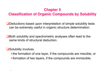
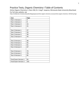
Diodes, OLED Construction andSimilarities to LEDsTo explain the OLED function, we will begin bybriefly introducing the function of a PN junctiondiode. Then we will discuss the general functioningmechanisms of an LED and OLED.A PN junction diode is a combination of a p-typesemiconductor and an n-type semiconductormaterial, creating a PN junction. The area in thisjunction, called a depletion layer, is created as astate of equilibrium between the two oppositelydoped semiconductors is formed. In this state,no movement is exhibited between the electronswithout a sufficient positively biased potential.Figure 1 (right) is a representation of thisconnection.Figure 1: PN junction representation7For current to flow (and for an LED/OLED to emita photon of light), you must introduce a potentialacross this PN junction. This potential causes areduction in the width of the depletion layer, allowing current to flow. It should be noted that the requiredforward bias potential for sufficient current flow is a characteristic of the materials utilized in the n-type andp-type semiconductors.An LED and an OLED function in the same manner, just with different materials utilized in their structures.The major difference is that OLEDs consist of organic layers (meaning carbon-based) sandwiched betweenan anode and a cathode. The anode is typically ITO, due to its clear properties. A sufficient potential appliedacross these terminals creates excitationwithin the organic recombination region.For these bounded pairs to return to theirinitial states, a photon (and also heat) mustbe released. Figure 2 (below) is a referenceto this general structure.Figure 2: General diagram of an OLED8Since white is not a single wavelength(or color), but rather a collection ofwavelengths, there are two popular waysto achieve a “white” output from LEDs. Thefirst is called phosphor converted, or PC.This method relies on the use of a shorterwavelength (InGaN) LED coated with ascintillator (type of phosphor), which mixeswith the shorter-wavelength-LED output tocreate a white output to the human eye.This method is identical for OLEDs.VioLight - Improving Color Solais Lighting, LLC All rights reserved.3
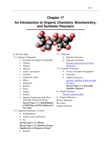
The other method for achieving white light with LEDs is called color mixing. This method relies on the mixingof multiple individual LEDs (sometimes within the same package) to achieve an overall white output inappearance. A major advantage for OLEDs is that they can achieve this same color-mixing technique using astacked architecture (thus the name SOLEDs). In this format, the SOLED utilizes three different PN junctions(red, green and blue), all stacked on top of one another as you can see in Figure 3 (below). Each junctionis separated by an insulator and can be individually controlled. Upon excitation these three junctions emitphotons of their respective properties, which mix to create a white output.Figure 3: SOLED structure8Current OLED ApplicationsThe most successful application of OLED panels to date has been the small-panel-display market. This consistsmainly of cell phones, tablets, wearables, and other small electronics. Traditionally, these displays were LCDpanels, which utilized white side-firing LEDs to illuminate the screens’ pixels. The software determined whichof these pixels to open or close, resulting in the screens’ image.SOLEDs are direct-view, meaning each pixel contains its own red, green and blue OLED. This architectureprovides numerous advantages. First, the individual colors provide a wider color gamut, resulting in theability to provide more saturated colors and deeper blacks. Second, the removal of the thin-film transistor(TFT) panel used in LCD means these devices are thinning and have a faster response time, which allows forsmoother image motion. Finally, the viewing angle of the OLED is typically wider, which helps to improve theoverall experience. The major disadvantage of OLEDs continues to be cost, so most manufacturers use themonly in high-end applications with smaller panels (due to low manufacturing yield).Interest is growing for the use of OLEDs in general-lighting. Today, these fixtures are offered by a smallquantity of manufacturers. Their target markets currently are specialty and decorative, because OLEDs do notmatch the performance, life or lower cost of LEDs. In most (if not all) current designs, fixture manufacturersare using multiple small-panel OLEDs (blue OLED plus phosphor) to achieve the desired output. This approachis similar to that of LEDs. However, this also means there are similar challenges in regard to panel consistency(mainly color, output and life). The main driving factor for these applications seems to be the ability toreshape the form of lighting beyond the traditional sense. While novel fixtures are important as technologyevolves, they do not fully satisfy the current state. For the mass market, the major focus should be to providean efficient, high-quality, cost-effective product.VioLight - Improving Color Solais Lighting, LLC All rights reserved.4
Challenges Facing OLED AdoptionAlthough much progress has been made with OLEDs, there remains significant hindrances to their widespreadadoption in the general-lighting market. Here we will address each of these challenges:1. Cost The most important factor comes down to cost. According to the U.S. Department of Energy, in 2015the expected cost of OLEDs remains at 25/kilolumen. By comparison, commercially available LEDs aresurpassing the 1/kilolumen threshold. The high of OLEDs cost is associated with a number of factorsincluding poor yield ratios, expensive topological structures for white-light generation (i.e., SOLED), andgeneral low capacity due to low demand.2. Life Current technology in general-lighting applications (fluorescent and, newly, LEDs) meets or exceeds50,000 hours of “usable” life. (The usable life of an LED is determined by the time taken for thelight output of the LED to drop to 70% of its initial output.) By comparison, commercially availableOLEDs currently sit around 15,000 to 25,000 hours of usable life. For applications with SOLEDs, thedegradations of the red, green and blue PN junctions are all different, causing color shift in the whitepanel if no special electronic controls are involved to correct the moving color point.3. Utilization efficacy The current efficiency of OLEDs is significantly less than is found in commercially available LEDs today(80lm/W vs. 180lm/W). In addition, one of the major advantages of LEDs is they can be easily lensed forprecise control as directional light sources -which was previously unheard of in general-lighting. OLEDsby comparison are a uniform, omnidirectional source, similar to that of fluorescent.4. Advances in LED light guides One of the major benefits often cited in support of OLEDs is their uniform diffuse-surface capabilitiesdue to their omnidirectional nature. However, in the past few years, optics and plastic manufacturershave found ways to use light guides in conjunction with LEDs to mimic this effect, effectively mitigatingthis advantage. These LED fixtures are available purchased today, are cheaper and are more efficientthan OLED panels of much smaller output and size.Conclusions on the State of OLEDsOLEDs are a very exciting technology. Over the next 10 years, it is expected they will dominate the displaymarket (cell phones, billboards, monitors, etc.). In the meantime, the LED lighting market continues to improvein terms of cost-effectiveness, color quality, life expectancy, and efficacy. A recent discussion at the LightingResearch Center, at Rensselaer Polytechnic Institute in Troy, N.Y. brought together chief technology officers frommajor lighting manufacturers in North America to discuss lighting in general. One of the major conclusions thatwere drawn from this meeting was that although OLEDs are an exciting technology, they will not replace LEDsfor most general-lighting applications. Instead, they will be used “where the diffuse surface is an advantagein the application at hand.”9 In addition, a recent research paper provided a follow-up to 1999 research,comprehensively outlining the promise and potential of LEDs for general illumination. 10 The findings reportedin that paper were that after LEDs fully realize their potential in the general-lighting market, there will be nojustifiable room left for further technological advancement, due to the high investment costs required. Inessence, LEDs will be the last technological shift for general illumination. 11 Hence, for lighting purposes, OLEDswill fail to provide a pleasant, well-lighted environment that is energy-efficient and cost-effective.VioLight - Improving Color Solais Lighting, LLC All rights reserved.5
References1. Bernanose, A. and Comte, M., Vouaux, P. 64, s.l. : Journal Chimie Physique, 1952, Vol. 50.2. P ositive hole injection into organic crystals. Kallmann, H. and Pope, M. 300, s.l. : The Journal of ChemicalPhysics, 1960, Vol. 32.3. Electroluminescence and band gap in anthracene. Sano, M., Pope, M. and Kallmann, H. 8, s.l. : The Journalof Chemical Physics, 1965, Vol. 43.4. Electroluminescence from polyvinylcarbazole films. Partridge, R. 6, s.l. : Polymer, Vol. 24.5. Organic electroluminescent diodes. Tang, C.W. and Vanslyke, S.A. 12, s.l. : Applied Science Letters, 1987,Vol. 51.6. Synthesis of a segmented conjugated polymer chain giving blue-shifted electroluminescence and improvedefficiency. Burn, P., et al. s.l. : Journal of the Chemical Society, 1992.7. Electronics Tutorials. PN Junction Diode. [Online] 2015. http://www.electronics-tutorials.ws/diode/diode 3.html.8. Forrest, S. The dawn of organic electronics. IEEE Spectrum, 2000.9. Wright, M. CTO session on the future of lighting kicks off LS13. LEDs Magazine, 2012.10. The case for a national research program on semiconductor lighting. Haitz, R., et al. Annual Forum of theOptoelectronics Industry Development Association, 1999.11. Haitz, R. and Tsao, J.Y. Solid-State Lighting: “The Case” Ten Years After and Future Prospects. Physica StatusSolidi, 2011.VioLight - Improving Color Solais Lighting, LLC All rights reserved.6
Current technology in general-lighting applications (fluorescent and, newly, LEDs) meets or exceeds 50,000 hours of “usable” life. (The usable life of an LED is determined by the time taken for the light output of the