Transcription
Advanced Thermal Management Solutions on PCBs for High Power ApplicationsGregor Langer1, Markus Leitgeb1, Johann Nicolics2, Michael Unger2, Hans Hoschopf3,Franz P. Wenzl41Austria Technologie & Systemtechnik AG, Fabriksgasse 13, 8700 Leoben, Austria234Institute of Sensor & Actuator Systems, Vienna University of Technology,Gusshausstraße 27-29, 1040 Vienna, AustriaTridonic Jennersdorf GmbH, Technologiepark 10, 8380 Jennersdorf, AustriaInstitute for Surface Technologies and Photonics, Joanneum Research Forschungsgesm.b.H.Franz-Pichler Straße 30, 8160 Weiz, AustriaABSTRACTWith increasing power loss of electrical components, thermal performance of an assembled device becomes one of themost important quality factors in electronic packaging. Due to the rapid advances in semiconductor technology,particularly in the regime of high-power components, the temperature dependence of the long-term reliability is a criticalparameter and has to be considered with highest possible care during the design phase.Two main drivers in the electronics industry are miniaturization and reliability. Whereas there is a continuousimprovement concerning miniaturization of conductor tracks (lines / spaces have been reduced continuously over the pastyears), miniaturization of the circuit carrier itself, however, has mostly been limited to decreased layer-counts and basematerial thicknesses. This can lead to significant component temperature and therewith to accelerated system degradation.Enhancement of the system reliability is directly connected to an efficient thermal management on the PCB-level. Thereare several approaches, which can be used to address this issue: Optimization of the board-design, use of base materialswith advanced thermal performance and use of innovative buildup concepts.The aim of this paper is to give a short overview about standard thermal solutions like thick copper, thermal vias, pluggedvias or metal core based PCBs. Furthermore, attention will be turned on the development of copper filled thermal vias inthin board constructions. In another approach advanced thermal management solutions will be presented on the boardlevel, exploring different buildup concepts (e.g. cavities). Advantages of cavity solutions in the board will be shown,which not only decrease the thermal path leading from the high power component through the board to the heat sink, butalso have an impact concerning the mechanical miniaturization of the entire system (reduction of z-axis). Such buildupsserve as packaging solution and show an increase in mechanical and thermal reliability.Moreover, thermal simulations will be conducted and presented in this paper in order to reduce production efforts and tooffer optimized designs and board buildups.KEYWORDSPCB, thermal management, power electronics, low thermal resistance, cavities
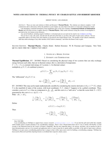
1.INTRODUCTIONModern power electronics is using power components like MOSFETs, IGBTs, GTOs, high brightness LEDs andmany more. Due to the enormously rapid advances in semiconductor technology, particularly in the regime ofhigh-power applications, the trend is going to smaller components with even higher switching speeds and highercurrent densities. In general a strong miniaturization trend for whole modules can be seen.With these trends and with increasing power loss densities the thermal performance of an assembly becomes oneof the most important quality factors in electronic packaging. New materials but also new and innovativeapproaches in the area of the PCB-substrates are required to meet the required reliability levels.Interest in power electronics has grown dramatically in the last few years with increasing need for electric powermanagement and control (Smart Grid), renewable energy generation and control (wind power, photovoltaic, fuelcell, etc.), electric transportation, and the desire to improve operating efficiency of heavy systems (trains,industrial motors, electric vehicle, etc.).Power electronic converters are found wherever there is a need to modify the voltage, current or frequency.These range in power from few milliwatts in mobile phones to hundreds of megawatts in HVDC (high-voltage,direct current) transmission systems (Fig. 1). Usually we think of electronics in the framework of information,where speed is the primary interest. In the context of power electronics improved efficiency and lower powerlosses are important.Figure 1. Range of power electronic applications (Source: iNEMI Technology Roadmaps, Jan 2013)2.THERMAL RESISTANCEDefinition of the thermal path and thermal resistanceFor steady-state considerations most frequently used measures for the thermal performance of an electronicmodule are either the junction temperature TJ of the semiconductor device with the significant power loss or –even more common – the thermal resistance Rth. The latter has to be defined by the temperature difference along a thermal path as e.g.,(1)where TC denotes the temperature of the interface of the case of the module and a cooler, and the power loss Plosscausing the temperature difference(2)Equation (2) is a useful practical approach to describe the thermal performance of a power assembly if TJ and TCare isotherms and the entire heat flow from TJ to TC equals Ploss. It should be noted that these conditions are notalways fulfilled. In small silicon transistors and diodes the rather small temperature gradients within the junctionIPC APEX EXPO 2014, Las Vegas, March 25-27, 20142
can frequently be neglected. However, as can be seen by a more detailed thermal investigation of a GaAs highpower transistor, depending on the considered semiconductor device, there are tremendously high temperaturedifferences within the junction itself [1]. Another frequently underestimated danger to misinterpret equation (2)arises if the case temperature is not enough uniform. To reach a uniform case temperature over an area as largeas possible is one major concern of the thermal management on the PCB level.A further approach to describe the thermal resistance Rth is shown in equation (3). It can be seen that the thermalresistance can be minimized by reducing the length d of the thermal path or by increasing the thermalconductivity of the material as well as by increasing the area of the contact pad A. As already stated in theintroduction there is a trend in miniaturization of the power components, so there is no chance to increase thearea. For this only the two first possibilities can be used to improve the thermal management of the system. Thatmeans the length of the thermal path through the PCB should be as short as possible, and the material betweencomponent and heat sink should have a thermal conductivity as high as possible.(3)Motivation for thermal managementThe main reason for deficiencies of electrical systems beside dust, vibration and humidity is by far the impact oftemperature. Therefore an efficient thermal management concept on the PCB is crucial for the reliability ofpower electronic systems.As an example we take high power LED applications, which are likely to dominate in the next years residentialand commercial lighting, signaling and vehicle headlights due to efficiency and extended lifetime. LEDs thatrange from 500 milliwatts to as much as 10 watts in a single package have become standard, and researchersexpect even higher power in the future.Thermal management is of critical importance for high power LEDs. More than 60% of the electrical powerinput is converted into heat and built up at the junctions of LED chips due to non-radiative recombination ofelectron-hole pairs and low light extraction.If that heat is not removed, the LEDs run at high temperature, which not only lowers their efficiency, but alsomakes the LED more dangerous, less reliable and shortens operating life [2,3]. Thus, thermal management ofhigh power LEDs is a crucial area of research and development.In this paper results of simulations and measurements of different LED-modules will be shown and should serveas representative of thermal solutions for general high power applications.3.STANDARD PCB-TECHNOLOGY FOR THERMAL MANAGEMENTOverview and short descriptionAn effective heat removal can be based either on a short heat conduction path to a heat sink perpendicularthrough the PCB (e.g. thermal vias) or by a conductor layer acting as a lateral heat spreader (extended thermalpads) or a combination of both.There are many different and well known build-ups for these heat removal concepts on PCBs. Thick copperapproaches on PCBs guarantee a very good lateral heat spreading effect due to the excellent thermal conductivityof the copper and are very well used to reduce hot spots.IMS (Insulated Metallic Substrates) are also state of the art and widely spread for thermal issues in electronicsystems. An IMS consists of a metallic base material (mostly aluminum or copper) with a thickness of about 0.5mm to 3.0 mm. On the metallic base material there is a thin dielectric layer (about 30 µm - 150 µm) with a highthermal conductivity (0.5 – 8.0 W/mK) in respect to standard FR4-material (ca. 0.3 W/mK). The copper designlayer is on top of the dielectric layer.IPC APEX EXPO 2014, Las Vegas, March 25-27, 20143
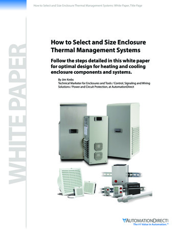
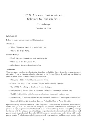
IMS show a very short heat conduction path through the thin dielectric layer, because the metallic base materialserves already as first heat sink. There are several different IMS variations available depending on the requestedperformance.Further build up concepts using a short heat conduction path to the heat sink are conventional through-holeplated glass fiber reinforced PCB technologies. A sufficient thermal performance in the lower power loss rangeup to several watts can frequently be achieved by reasonable numbers for via count, via diameter, and holeplating thickness [4]. Figure 2.a shows a scheme of a PCB with open through holes serving as open thermal vias.In figure 2.b an example of a footprint design is shown. It can be seen that the thermal vias are situated in theextended thermal pads beside the pad, where the component will be placed. So, to avoid the well-known problemof solder soaking, it is not possible to place open thermal vias directly underneath a component. Due to this fact,the thermal path is elongated, because the heat has to be spread first laterally on the surface before it can beguided perpendicular through the PCB to the heat sink (Fig. 2.c).A schematic cross section as depicted in figure 3.a demonstrates a special via plating technology featuringplugged vias with a homogeneous copper layer on the front faces. In contrast to the concept with open vias, thisbuild up allows vias directly beneath a component, which also reduces the thermal path. Figure 3.b shows amicroscopic view of a cross section of this type of PCBs.b)c)a)Figure 2. PCB with open thermal vias: a) Scheme; b) design; c) thermal patha)b)c)Figure 3. PCB with plugged thermal vias: a) Scheme; b) cross section; c) thermal pathExperimental setupTest objects were selected with following specifications: DK2, (FR4, thickness 1 mm, pads with plugged thermal vias) DK6, (FR4, thickness 0.2 mm, open thermal vias with 0.3 mm diameter, laminated onto 1.5 mm thick Alsubstrate with a 90 µm thick prepreg) IMS1, (70 µm thick copper clad, 110 µm thick dielectric, thermal conductivity 0.5 W/(mK), Al-substratethickness 1.5 mm)IPC APEX EXPO 2014, Las Vegas, March 25-27, 20144
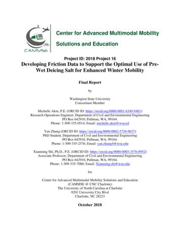
IMS3, (70 µm thick copper clad, 125 µm thick dielectric, thermal conductivity 4 W/(mK), Al-substratethickness 1.5 mm)All PCB samples were prepared with a size of 30 mm x 40 mm. The layout allowed to test two power LEDs atthe same time (Fig. 4.a) whereby the comparatively large via arrays should help to maximize heat spreading.Most important qualities of an experimental set-up are to simulate boundary conditions as close as possible to thefollowing extreme conditions:a)The PCB itself acts as a heat sink by conducting the heat flux in the plane direction and dissipating e.g.by natural convection and radiation.b)The PCB acts as mean to interconnect the power component with a cooler and to help spreading theheat flux uniformly over the entire attachment surface of the cooler.In this section we compare the thermal performance of FR4-based PCBs with thermal via arrays (two differentmodifications: with open vias and with plugged vias) and IMS in an experimental set-up according to conditionb). For this purpose a water-cooled copper block was used as a heat sink with constant temperature. The sampleswere attached to the copper block using an equally distributed thin layer of thermal grace with a thermalconductivity of 0.6 W/(mK). The samples were pressed against the copper block with pointed plastic screws inorder to keep the thermal resistance of this interface as stable as possible without heat removal from the top side(Fig. 4.b).a)b)Figure 4. LED module mounted on water-cooled heat sink:a) Top view of test sample; b) sample under testTemperature distributions of the top side of the samples during operation with the nominal forward current(If 700 mA) were recorded using a high-end thermography system. An emissivity correction was made by acalibration measurement with a miniaturized thermocouple at the LED pad.From evaluation of transient thermal response on power-on-steps with the nominal power value we see that thefinal temperature distribution on the entire sample surface is obtained within only a few seconds in all cases. Thetemperature distributions obtained by IR thermography in the steady state are compared for all four sample typesin figure 4. During experiments with the nominal forward current a voltage drop of 4Uf 13.5 V was measured(four single LED elements in one module, connected in series). Assuming an average photonic efficiency of 20% we considered a continuous power loss of 7.56 W per sample. Since establishing of the junctiontemperature was related to high uncertainties we defined the pad-to-cooler thermal resi
PCB, thermal management, power electronics, low thermal resistance, cavities . IPC APEX EXPO 2014, Las Vegas, March 25-27, 2014 2 1. INTRODUCTION Modern power electronics is using power components like MOSFETs, IGBTs, GTOs, high brightness LEDs and many more. Due to the enormously rapid advances in semiconductor technology, particularly in the regime of high-power applications, the