Transcription
NCB PeriprostheticFemurPlate SystemSurgical Technique
3NCB Periprosthetic Femur System – Surgical TechniqueTable of ContentsIntroduction4System Features and Benefits9Indications and Contraindications13Periprosthetic Femur Fracture Classification14NCB Periprosthetic Plate Positioning and Screw Fixation16NCB Screw Insertion20Screw Insertion for NCB Periprosthetic Trochanter Plate22NCB Periprosthetic Proximal Femur Plate – Surgical Technique23NCB Periprosthetic Distal Femur Plate – Surgical Technique33NCB Curved Femur Shaft Plate – Surgical Technique39NCB Bone Spacers (Optional)44NCB Blind Screw Inserts (Optional)44Tips and Tricks for the NCB Periprosthetic Femur System45Implant Removal46Product Information – Implants47Product Information – Instruments51Planning Aid54
4NCB Periprosthetic Femur System – Surgical TechniqueIntroductionThe NCB (Non-Contact Bridging) Periprosthetic Femur System is a line of polyaxiallocking plates designed for the treatmentof femur fractures, particularly periprosthetic femur fractures. It consists primarilyof a Proximal Femur Plate, a Distal FemurPlate, and a Curved Femur Shaft Plate.In addition to that a Trochanter Plate isavailable to reattach the greater trochanter in combination with a ProximalFemur Plate.The NCB Periprosthetic Proximal andDistal Femur Plates are wider in thearea of the prosthesis and have offsetholes that may allow bicortical screwplacement in the area of the prosthesis.NCB Periprosthetic Proximal Femur PlateNCB Periprosthetic Trochanter Plate assembled with NCB Periprosthetic Proximal Femur Plate (short)NCB Periprosthetic Distal Femur PlateNCB Curved Femur Shaft Plate
5NCB Periprosthetic Femur System – Surgical TechniqueThe labeling of the NCB PeriprostheticProximal and Distal Femur Plates corresponds with number of NCB Plate holes ina specific way.MIS InterfaceProximal Plates: the number of holesaccording label text the number of allNCB screw holes distal to the MIS interface. 3 3Distal Plates: the number of holesaccording label text the number of allNCB screw holes proximal to the MIS interface 3 .Example: 12 hole plate 2 x 3-hole pattern 6.211815129 holesThe NCB Periprosthetic Trochanter Plate isavailable in two different sizes (differentwidth) whereas the height is the same.Due to the anatomical shape of the proximal femur a left and right version isoffered.left wideleft narrowright narrowright wide
6NCB Periprosthetic Femur System – Surgical TechniqueThe NCB System Technology allows forpolyaxial screw placement (30 cone)with screw locking achieved through theuse of locking caps that are threaded intothe plate holes. The locking constructallows for improved stability especiallyin osteopenic bone. Before locking,the screws can act as lag screws andbe used for fracture reduction; a benefitwhich is not offered with standardlocking systems.30 NCB 30 Cone PolyaxialityIn the locked mode, the NCB PeriprostheticPlate acts as an internal fixator withoutcontact between the plate and the bonesurface, which may reduce the risk ofperiosteal blood supply impairment. ThisNon-Contact Bridging concept can also becontrolled specifically through the use of1, 2, or 3mm spacers, which are threadedinto the plate holes prior to plate insertion.NoncontactAngular stability with the NCB Locking CapsLocking cap 8mmBlind screw insertNCB Non-Contact BridgingSpacer 1 to 3mm
7NCB Periprosthetic Femur System – Surgical TechniqueThe NCB Periprosthetic Trochanter Platehas a built in screw technology whichgives surgeons the ability to create afixed-angle construct while using familiarplating techniques. The locking screwheads contain male threads, while theholes in the plates contain femalethreads. This allows the screw head to bethreaded into the plate hole, locking thescrew into the plate. The heads aredesigned to c reate a nearly flush profileon the plate, which helps to decreasesoft tissue irritation.The plate also allows anatomical reduction of the fracture f ragments using standard cortical screws (non-locking).Double-lead threads(Double the shaftthread pitch)Shallow threadprofile compared totraditional screwsHead and shaftadvance at same rateinto plate and boneNOTE: If lag screw fixation is necessaryfor any fragment, the lag screw must beinserted before inserting locking screwsinto that fragment.The NCB Periprosthetic Trochanter Platecontains different hole types.a) Hex Button holes: used to place HexButtons in combination with cablesaround the plate and the femoral bone.b) Clearance holes for K-Wires: used forpreliminary fixation of the plates to thebone.c) Connection Screw holes: used toassemble the NCB PeriprostheticTrochanter Plate to the NCB PeriprostheticProximal Femur Plate. Screws must betightened to 6Nm using the corresponding torque screwdriver (REF 02.00024.021).d) 3.5mm Screw holes: used to placeZimmer Universal Locking System(ULS) locking screws or cortical screws(non-locking).e) Clearance holes for NCB Screw holes:used to place poly-axial locking screws(NCB Screws) or blue NCB Cable Buttons(REF 47-2232-060-01) in combinationwith cables around the plate andfemoral bone.Note: Do not use the gold NCB LockingPlate Cable Button (REF 47-2232-06000) or Hex Button (REF 00-2232-002-35)in any clearance holes for NCB screwholes on the NCB Periprosthetic Trochanter Plate. If attaching cables, theblue NCB Cable Button (REF 47-2232060-01) must be used in these holeswhen the Trochanter plate is attached.Using the wrong cable fixation optionincreases the likelihood of disengagement of the button which can lead torefracture or damage to the bone.
8NCB Periprosthetic Femur System – Surgical TechniqueThe surgical technique is based on wellknown standard plate osteosynthesistechniques, which give the surgeontactile feedback regarding bone qualityduring drilling and tightening of thescrews. In addition, with the use oflocking caps the screws can be lockedand made angularly stable.The NCB Periprosthetic Femur Systemallows for extensive flexibility in the treatment of periprosthetic fractures. Thepolyaxial NCB Plate technology, alongwith the offset plate holes, may allow forbicortical screw fixation around the stemof the implanted prosthesis. In this way,the surgeon can achieve better constructstability than with cables with less damage to the soft tissue. And becauseof the Non-Contact Bridging concept, therisk to the periosteal blood supply maybe reduced.Additionally, fixation using cables andcable buttons is possible for those caseswhere bicortical screw fixation cannot beachieved. Both techniques (lockingscrews and cables) may also be combined. Blunt tip unicortical NCB Screwsare also available, creating a systemwhich offers comprehensive solutions forthese difficult fractures.Bicortical screw anchoragearound the stem with NCBScrewsFixation using uni- and bicortical screws,as well as cables andcable buttons
9NCB Periprosthetic Femur System – Surgical TechniqueSystem Features and BenefitsNCB Periprosthetic Proximal andDistal Femur PlatesInnovative Periprosthetic Plate Design Specific anatomical fit to the bone inleft and right designs Wide plate design in the periprostheticregion to allow for bicortical screwfixation around the prosthesis, andnarrow plate design on the rest of theplate to minimize soft tissue disruption.MIS Interface MIS interface, consisting of threeholes, allows for connection tothe Targeting Device. See surgical technique REF 97-2370-010-00for specific instructions.Diagonal Three Hole PatternDiagonal three hole pattern allows formore screw options: Off-set holes allow for easier screwplacement around the prosthesis andstable bicortical screw fixation. Theholes accommodate 5.0mm NCBScrews, and two types of 4.0mm NCBScrews for use when there is minimalbone around the prosthesis. The central holes can accommodatethreaded 5.0mm NCB UnicorticalScrews, threaded Cable Buttons andCables, when bicortical f ixation cannotbe achieved.Diagonal Three HolePatternDifferently ShapedScallopsDifferently Shaped Scallops Reduced and uniform plate stiffness. Better plate contouring across solidcross-sections, away from holes.Divergent Screw Alignment Increased pull-out resistance. Reduced risk of fracture due to linearperforation of the bone.Divergent Screw Alignment(plate bottom side)MIS Interface
10NCB Periprosthetic Femur System – Surgical TechniqueNCB Periprosthetic ProximalFemur PlateTrochanter Plate InterfaceTwo threaded holes allow for connectionwith the NCB Periprosthetic TrochanterPlate to cover periprosthetic fractures inthe trochanteric area.K-Wire HolesK-Wire HolesTwo proximal k-wire holes and one distalk-wire hole allow for easier preliminaryfixation.Trochanter PlateIn combination with a Proximal FemurPlate the Trochanter Plate offers usage ofULS locking screws or cortical screws(non-locking) to re-attach the greater trochanter.Trochanter Plate InterfaceAdditional holes allow for usage of HEXbuttons to fix cables to the NCB Periprosthetic Trochanter Plate.Short Proximal Femur PlateOne adjustment slot is added to this specific plate which allows for preliminaryfixation of the plate.NCB Periprosthetic DistalFemur Plate95 Angled Distal HoleThe most distal central plate hole is angled at 95 to the plate shaft to allowscrew insertion parallel to the joint. Thiscan help reduce the fracture and mayfacilitate realignment of the anatomicaxis of the femur.K-Wire Holes One proximal k-wire hole aids in pre liminary plate fixation to bone. Three Distal k-wire holes are parallel tothe most distal central plate hole to aidin femoral realignment.95 Angled Distal Hole95 Angled DistalK-Wire Holes
11NCB Periprosthetic Femur System – Surgical TechniqueNCB Curved Femur Shaft PlateSymmetric DesignOne plate for left and right femurs dueto symmetric design.Compression SlotsTwo compression slots allow 1mmof compression each.Articulated Tension Device HoleK-Wire HolesTwo k-wire holes at each end of the plateallow easier preliminary plate fixation.Articulated Tension Device HolesOne hole at each end of the plate allowsfor connection of the Articulated TensionDevice to achieve additional compression,if needed.K-Wire HolesCompression SlotsArticulated Tension Device HoleNCB Periprosthetic FemurSystemBroad Screw OptionsSix different NCB Screw types and two different 3.5mm ULS locking screwsand cortical screws (only for NCB Periprosthetic Trochanter Plate) are offeredwith the NCB Periprosthetic Femur System, to allow both bicortical and unicortical fixation.Broad Screw Options mmDescription5NCB Screws5NCB Unicortical Screws5NCB Cancellous Screws4NCB Screws4NCB Screws, Deep Thread3.5ULS Locking Screw3.5Cortical Screw5NCB MotionLoc ScrewsSpecific Instruments for PeriprostheticFracturesSlightly oversized drill bits and drill guidesare offered with the NCB PeriprostheticFemur System, to reduce the risk of cracksin the cement mantle when placingscrews around a cemented prosthesis.NCB Instruments for overdrilling into cement
12NCB Periprosthetic Femur System – Surgical TechniqueCable Fixation OptionsThe following products from the Zimmer Cable-Ready Cable GripSystem are compatible with the NCB Periprosthetic Femur System:See data sheet REF 97-2232-015-00 formore specific instructions.NCB Locking PlateCable Button, 2.5mm, Hex DriveHex Button, 3.5mmCable Assembly Cerclage,1.8mm Sterile Material: Ti6Al4V Sterile Material: C.P. Titanium Sterile Material: CoCrREF 47-2232-060-00 Color: Gold*REF 47-2232-060-01 Color: BlueREF 00-2232-002-35REF 00-2232-002-28REF 00-2232-004-18ApplicationThis Cable Button is threadeddirectly into the NCB Plate hole toprovide a positioning point forthe CableInstructionsTo insert, use the 2.5mm hexscrewdriver to thread the cablebutton in to the plate hole. Do notfully tighten to allow the slots inthe button to align with the cable.ApplicationThis Hex Button fits into thestandard hex in the screw head(3.5mm hex). Therefore, it canbe inserted into the NCB Screwhead, or into the NCB LockingCap or directly into the specificholes of the NCB PeriprostheticTrochanter Plate.To remove, use 2.5mm hex screwdriver to unthread the cablebutton from the plate hole.NoteIf adding cables to the NCB screw holes of the NCB Periprosthetic Trochanter plate, ensure that only the compatible blue NCB Cable Button (REF 47-2232-060-01)is used. See page 7 for details.Cable Fixation withCable ButtonCable Fixation Options* Not available in Europe, Middle East, and AfricaCable Fixation Options(NCB Periprosthetic Trochanter Plate)Cable Fixation withHex Button
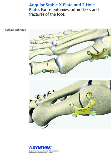
13NCB Periprosthetic Femur System – Surgical TechniqueIndications and ContraindicationsIndicationsThe NCB Periprosthetic Femur PolyaxialLocking Plate System is indicated fortemporary internal fixation and stabilization of fractures and osteotomies oflong bones, including: Periprosthetic fractures Comminuted fractures Supracondylar fractures Fractures in osteopenic bone Nonunions MalunionsThe NCB Periprosthetic Trochanter Plate when used in combination with NCB Periprosthetic Proximal Femur Plate,short (Length 115mm) is indicated fortemporary internal fixation and stabilization of fractures and osteotomies of thegreater trochanter.NCB PeriprostheticTrochanter Plate NCB Periprosthetic Proximal FemurPlates (Length 245mm, 285mm,324mm, 363mm, 401mm) is indicatedfor temporary internal fixation and stabilization of fractures and osteotomies of theproximal femur. In addition, both combinations are indicated for: Re-attachment of the greater trochanter following osteotomy in THA Re-attachment of the greater trochanter following fracture of greater trochanter Periprosthetic fractures Comminuted fractures Fractures in osteopenic bone Nonunions MalunionsContraindications All concomitant diseases that mayimpair the fixation of the implant and/or the success of the intervention Lack of bone substance or poor bonequality which makes stable seating ofthe implant impossible Acute or chronic, local or systemicinfections Allergy to the implanted materials Severe muscular, neural or vascular diseases that endanger the extremities involved Loose prosthesis, which requiresimmediate revision If the NCB Periprosthetic TrochanterPlate is used in combination with theNCB Periprosthetic Proximal FemurPlate short (Length 115mm), FemoralNeck Fracture is a contraindication aswell
14NCB Periprosthetic Femur System – Surgical TechniquePeriprosthetic Femur Fracture ClassificationComprehensive classification systemsfor periprosthetic femur fractures arethe Vancouver classification for fracturesfollowing Total Hip Arthoplastly (THA),and the Lewis and Rorabeck Classifi cation for fractures following a TotalKnee Arthoplastly (TKA).Vancouver ClassificationFractures around Hip ImplantsAccording to the Vancouver classifications, Type B1 (fracture located aroundthe tip of the hip prosthesis) andType C periprosthetic fractures (fracturelocated well below the tip of the hipprosthesis), both with a stable implant,may be treated with ORIF (Open Reduction Internal Fixation). For such fractures,either the NCB Periprosthetic ProximalFemur Plate or the NCB Curved FemurShaft Plate may be used.Vancouver ClassificationType A Fracture: occurs at the proximalpart of the femur with displacement ofthe greater trochanter or lesser trochanterType AType B1Type B1 Fracture: occurs around or justdistal to a well-fixed femoral stemType B2 Fracture: occurs around orjust distal to a loose femoral stem withadequate proximal boneType B3 Fracture: occurs around orjust distal to a loose femoral stem withpoor proximal bone stockType C Fracture: occurs well distal tothe stem tipType CType B2Type B3
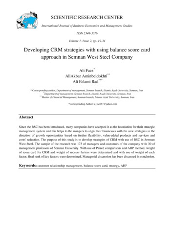
15NCB Periprosthetic Femur System – Surgical TechniqueFractures around Knee ImplantsLewis and Rorabeck ClassificationPeriprosthetic femoral fractures followinga TKA which are usually treated withORIF are Type II fractures of the Lewisand Rorabeck Classification (displacedfractures where the knee prosthesisis intact). For such fractures the NCBPeriprosthetic Distal Femur Plate may beused.Lewis and Rorabeck ClassificationType I Fracture: Non-displaced fracture.Prosthesis intactType IType II Fracture: Displaced fracture.Prosthesis intactType III Fracture: Non-displaced or displaced fracture. Prosthesis loose or failingType IIType III
16NCB Periprosthetic Femur System – Surgical TechniqueNCB Periprosthetic Plate Positioning and Screw FixationRecommended NCB PeriprostheticPlate Positioning Ensure that the length of the NCBPeriprosthetic Proximal Femur or DistalFemur Plate allows for screw placementaround the existing prosthesis alongthe diagonal three hole pattern in thewidest area of the plate. The widest part of the plate should beplaced on the fracture site. Do not placethe narrow part of the plate over thefracture site.TransitionNarrow plate designWide plate design: Location of the periprosthetic fractureNCB Periprosthetic Proximal Femur Plate and fracture locationTransitionWide plate design: Location of the periprosthetic fractureNCB Periprosthetic Distal Femur Plate and fracture locationNarrow plate design
17NCB Periprosthetic Femur System – Surgical TechniqueRecommended NCB ScrewFixationThe NCB Periprosthetic Femur Systemoffers five different types of polyaxiallocking screws, four of them are designedfor bicortical purchase, and one of themis designed for unicortical purchase.In addition, Ø5.0mm Zimmer MotionLocScrews are also compatible with the NCBPeriprosthetic Femur System and have amore specific instruction in the SurgicalTechnique (REF: 97-3161-004-00).Recommended NCB Screw usage for NCBPeriprosthetic Proximal Femur and DistalFemur Plates: Use two bicortical 5.0mm NCB Screwsclose to the fracture on each side of thefracture. Wherever possible, use 5.0mm bicortical NCB Screws. For thin cortical bonenear the prosthesis, the 4.0mm NCBScrews may be used.Note: the 4.0mm NCB Screws, deepthread are only recommended for usearound the implanted prosthesis whenthe cortical wall is too thin to use evenwith the 4.0mm NCB Screws. They arenot r ecommended for use near the fracture site.The 4.0mm NCB Screws, Deep Threadhave a smaller core diameter than the4.0mm NCB Screws (2.9mm versus3.4mm), which allows for a more aggressive thread design for improvedanchorage in thin bone. Furthermore,as the core diameter is smaller, less boneis removed during drilling and screwinsertion.NCB Screws – BicorticalScrew TypeUnicorticalCortical5mmCortical4mmCortical4mm Deep ThreadCancellousPartially threadedCorticalBlunt Tip5mm4mm4mm5mm5mmCore ose to the fracturearea, in the shaftarea, or where there isno risk of hitting theprosthesisAway from the fracturearea to achieve bicortical fixation around theprosthesisAway from the fracturearea to achieve bicortical fixation aroundthe prosthesis whenfixation even with the4.0mm corticalstandard screws isimpossibleMetaphyseal area of theDistal FemurFor use whenbicortical fixationcannot be achieved4.3 / 4.5mm3.3 / 3.5mm3.0mm2.5mm4.3 / 024.330*Tap .341Drill Guide 4.331Outer REFREF SterileApplicationDrill Bit Drill Bit REFNCB Screw portfolio for the NCB Periprosthetic Femur System* Titanium nitride coated drill bits for drilling into the cement mantleWarningIf only unicorticalscrews are used,the use of cables isrequired
18NCB Periprosthetic Femur System – Surgical TechniqueRecommended Screw Fixationfor NCB Periprosthetic TrochanterPlateThe NCB Periprosthetic Femur Systemoffers two additional types of screws tobe used with the NCB PeriprostheticTrochanter Plate, ULS locking screw andcortical screw (non-locking).Recommended Screw usage for NCB Periprosthetic Trochanter Plates: Use at least three 3.5mm screwsplacing them both anterior and posteriorto the prosthesis. If using two 3.5mm screws in themost proximal holes to securethe t rochanteric fragment, add twoadditional screws distally. Screws should be placed through fracture zone, or osteotomy gap.FOR EMEA (Europe, Midle East, and Africa) ONLY:Instead of using the3.5mm cortical screws from the ULS system(00-4935-xxx-35) standard 3.5mm corticalscrews (02.03131.xxx) can be implanted aswell.ULS ScrewsCortical Screws (FOR EMEA ONLY)Locking3.5mmCortical3.5mmCortical3.5mmOuter 3.5mm3.5mm3.5mmCore -xxx-0102.03131.xxx—Trochanteric area inlocked modeTrochanteric area innon-locked modeTrochanteric area innon-locked mode2.7mm2.5mm2.5mmDrill Bit REF00-2360-205-2700-4807-180-2500-4807-180-25Tap REF00-2360-153-3500-4811-110-3500-4811-110-35Drill Guide REF00-2360-020-2700-4808-035-0100-4808-035-01Screw TypeREFREF SterileApplicationDrill Bit Screw portfolio for the NCB Periprosthetic Femur System(Trochanter Plate)* Longer sizes (60mm – 90mm, 5mm steps) are available upon request sterile packed** Longer sizes (60mm – 95mm, 5mm steps) are available upon request sterile packed
19NCB Periprosthetic Femur System – Surgical TechniqueStandard NCB Screw FixationStandard NCB Screw Fixation1.Shows a standard NCB Plate used in a non periprosthetic fracture.Recommended NCB Periprosthetic Screw FixationStandard NCB Screw Fixation2.Indicates recommended NCB Screw fixation for the NCB Periprosthetic Plate in periprosthetic fractures. Bicortical screw fixationwith at least four NCB Screws is recommended along the diagonal three hole pattern in the widest section of the plate. Placescrews both anterior and posterior to the prosthesis.Warning: Do not insert three screws in one diagonal three hole pattern, because it creates a stress riser in the bone.When no prosthesis is present beneath the plate standard NCB Screw fixation can be applied.Note: To prevent thread stripping and allow for adequate bone purchase, pass screws as centrally through the bone as possible.In addition, irrigation may be used during drilling to help p revent thermal necrosis.Alternative NCB Periprosthetic Screw FixationStandard NCB Screw Fixation3.Demonstrates a situation where four bicortical NCB Screws cannot be placed along the diagonal three hole pattern in the widepart of the plate. To ensure s table f racture fixation, the use of one or two divergent 5.0mm NCB Unicortical Screws is recommended. If only one bicortical screw can be placed in the offset holes of a given diagonal three hole pattern, place one 5.0mmNCB Unicortical Screw in the c entral hole of that three-hole pattern.Standard NCB Screw FixationAlternative NCB Periprosthetic Screw Fixation with Cable4.Demonstrates a situation where a threaded cable button and cable are used as an optional fixation method, when additional fixation is required.NCB Screw 5mmNCB Screw 5 or 4mm, orNCB Screw 4mm, Deep ThreadNCB Unicortical Screw 5mmCable Ready Cable-Button and CableRecommended NCB Screw fixationfor the NCB Periprosthetic ProximalFemur and Distal Femur PlatesWarning: Do not insert three screws in onediagonal three hole pattern, because it createsa stress riser in the bone.
20NCB Periprosthetic Femur System – Surgical TechniqueNCB Screw InsertionFor All Types of NCB Screws andNCB Locking CapsNCB Screw 5.0mmNCB Unicortical Screw 5.0mm1. To insert a 5.0mm NCB Screw(REF 02.03150.xxx) use the 4.3mmNCB Drill Guide (REF 02.00024.011)and drill with the 4.3mm drill bit(REF 02.00024.002).Warning: If only unicortical screws areused, the use of cables is required. Do not hit the prosthesiswith the tip of the drill, tap or screw. Take care to avoid collision of thescrews by choosing the appropriateplate holes and screw lengths. Press the NCB Drill Guide into the platehole perpendicular to the plate andthen tilt it in the preferred direction.The drill guide needs to be in constantcontact with the bottom ring of thehole. The guide limits the angulation to15 from the perpendicular axis of theplate or a cone of 30 for placing alocked NCB Screw. Always use the drillguide since it prevents selection of anexcessive screw angle and failure ofsubsequent locking. Screws may be inserted under powerbut should be final tightened by handonly. Lock the construct, insert andtighten the NCB Locking Caps(REF 02.03150.300) by using the NCBTorque Limiting Screwdriver, 6Nm(REF 02.00024.021) until a click soundis heard. Make sure the screwdriveris not tilted during its usage. If thedriver is tilted, it could damage thehex drive and might complicate theextraction of the implants.For Zimmer MotionLoc ScrewsSee surgical technique REF 97-3161-004-00for more specific instructions.In case of hard cortical bone or thepresence of a cement mantle, tap the cortex with the 5.0mm NCB Tap(REF 02.00024.341). Remove the4.3mm NCB Drill Guide before usingthe NCB Tap.Note: The 4.3mm drill bit can drill amaximum of 105mm deep when usedwith the drill guide. If a longer screw isneeded, remove the drill guide and drillthe additional depth free hand.Note: Inserting screws in the presence ofa cement mantle can cause cracks, whichmay cause loosening of the prosthesis.Overdrilling by using a drill bit of aslightly larger diameter (0.2mm) mayreduce cracking in the cement mantleduring screw insertion. Instead of the4.3mm drill bit, use the 4.5mm drill bit(REF 02.00024.330) and its correspondingdrill guide (REF 02.00024.331).12. Use the NCB Measuring Device(REF 02.00024.005) to determine theappropriate screw length and insertthe NCB Screw using the NCB HexagonalScrewdriver (REF 02.00024.023) orscrewdriver shaft (REF 02.00024.024).3. To lock the construct, insert the NCBLocking Caps (REF 02.03150.300) asdescribed at the beginning of this section.1. To insert a 5.0mm NCB UnicorticalScrew (REF 02.03151.0xx) usethe 4.3mm NCB Drill Guide(REF 02.00024.011) and drill with the4.3mm drill bit (REF 02.00024.002).In case of hard cortical bone or thepresence of cement mantle, tap thecortex with the 5.0mm NCB Tap(REF 02.00024.341). Remove the4.3mm NCB Drill Guide before usingthe NCB Tap.Note: Inserting screws in the presence ofa cement mantle can cause cracks,which may cause loosening of theprosthesis. Overdrilling by using a drill bitof a slightly larger diameter (0.2mm) mayreduce cracking in the cement mantleduring screw insertion. Instead of the4.3mm drill bit, use the 4.5mm drill bit(REF 02.00024.330) and its correspondingdrill guide (REF 02.00024.331).22. Use the NCB Measuring Device(REF 02.00024.005) to determine theappropriate screw length andinsert the NCB Unicortical Screw usingthe NCB Hexagonal Screwdriver(REF 02.00024.023).Note: When using the NCB MeasuringDevice to measure the length of the NCBUnicortical Screw needed, the device willnot hook the far cortex of the bone. Usethe screw length measured. Do not use alonger screw.3. To lock the construct, insert the NCBLocking Caps (REF 02.03150.300) asdescribed at the beginning of this section.1, 2J. Kampshoff et al.: The treatment of periprosthetic fractures with lockingplates: effect of drill and screw type on cement mantles: a biomechanicalanalysis, Archives of Orthopedic and Trauma Surgery, Springer, March 2009.
Drilling of the lockingholes21NCB Periprosthetic Femur System – Surgical TechniqueNCB Cancellous Screw 5.0mmNCB Screw 4.0mmNCB Screw 4.0mm,Deep Thread1. To insert a 5.0mm NCB CancellousScrew (REF 02.03152.xxx) use the NCB2.5mm Drill Guide (REF 02.00024.010)and use the 2.5mm drill bit(REF 103.25.180).1. To insert a 4.0mm NCB Screw(REF 02.03155.0xx) use the 3.3mmNCB Drill Guide (REF 02.00024.111)and drill with the 3.3mm drill bit(REF 02.00024.118).1. To insert a 4.0mm NCB Screw, DeepThread (REF 02.03154.0xx) use the3.0mm NCB Drill Guide (REF 02.00024.310)and drill with the 3.0mm drill bit(REF 02.00024.301).In case of hard cortical bone drill thecortex with a 4.3mm drill bit(REF 02.00024.002) by using the 4.3mmNCB Drill Guide (REF 02.00024.011).In case of hard cortical bone or thepresence of the cement mantle, tap thecortex with the 4.0mm NCB Tap(REF 02.00024.340). Remove the 3.3mmNCB Drill Guide before using the NCB Tap.In case of hard cortical bone or the presence of the cement mantle, tap the cortexwith the 4.0mm NCB Tap, Deep Thread(REF 02.00024.305). Remove the 3.0mmNCB Drill Guide before using the NCB Tap.Note: Inserting screws in the presenceof a cement mantle can cause cracks,which may cause loosening of the prosthesis. Overdrilling by using a drill bitof a slightly larger diameter (0.2mm) mayreduce cracking in the cement mantleduring screw insertion. Instead of the3.3mm drill bit, use the 3.5mm drill bit(REF 02.00024.325) and its correspondingdrill guide (REF 02.00024.326).12. Use the NCB Measuring Device(REF 02.00024.005) to determine theappropriate screw length and insert theNCB Screw, Deep Thread using the NCBHexagonal Screwdriver (REF 02.00024.023)or screwdriver shaft (REF 02.00024.024).Note: Use the 5.0mm NCB CancellousScrews only in cancellous bone.Note: The 2.5mm drill bit can drill amaximum of 90mm deep when usedwith the drill guide. If a longer screwis needed, remove the drill guide anddrill the additional depth free hand.2. Use the NCB Measuring Device(REF 02.00024.005) to determine theappropriate screw length and insertthe NCB Cancellous Screw using theNCB Hexagonal Screwdriver(REF 02.00024.023) or screwdrivershaft (REF 02.00024.024).Cancellous screws are partially threadedand can be used as lag screws to reducethe fracture and obtain close contactbetween the plate and the bone.3. To lock the construct, insert theNCB Locking Caps (REF 02.03150.300) asdescribed at the beginning of this section.12. Use the NCB Measuring Device(REF 02.00024.005) to
6 NCB Periprosthetic F Syst Surgical Technique NCB 30 Cone Polyaxiality Angular stability with the NCB Locking Caps 30 Non contact NCB Non-Contact Bridging Blind screw insert Locking cap 8mm Spacer 1 to 3mm The NCB System Technology allows for polyaxial screw placement (30 cone) with screw locking achieved through the