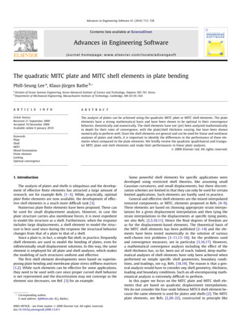
Transcription
Base plate in bending andanchor bolts in tensionFrantišek WaldCzech Technical University, Faculty of Civil Engineering, Prague, Czech RepublicZdeněk SokolCzech Technical University, Faculty of Civil Engineering, Prague, Czech RepublicJean-Pierre JaspartUniversité de Liège, Institut du Génie Civiel Départemant MSM, BelgiumThis paper describes the behaviour of the base plate in bending and the anchor bolts intension, which are the major components of a base plate connection. An analytical model hasbeen derived to predict the component characteristics – the resistance and the stiffness. Adescription is given of how the behaviour is influenced by contact between the base plate andthe concrete surface. The presented analytical model has been verified by tests and a finiteelement simulation.Key words: Steel structures, column bases, component method, Eurocode 3, anchor bolt1IntroductionThe base plate connections have a different configuration compared to the beam to columnend plate connections. Thick base plates are designed to transfer compression forces intothe concrete block and are stiffened by the column and the additional stiffeners whennecessary. The anchor bolts are longer compared to the bolts used in end plates due topresence of washer plates and grout, thick base plate and the part embedded in theconcrete block. The length of the anchor bolts allows deformation and separation of thebase plate when the anchor bolts are loaded in tension. Different behaviour should beconsidered when strength, stiffness and rotational capacity of the base plate loaded bybending moment have to be predicted, see [1].The column base stiffness is in particular influenced by behaviour of the tension part of thebase plate, see [2]. Published models of the column base loaded by bending momentHERON Vol. 53 (2008) No. 1/221
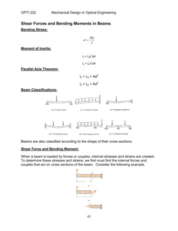
include different levels of modelling of the tension part of the column base from verysimple models to very complex solution, see [3]. The knowledge of the behaviour of theend plates in beam to column connections was extended in [4] by most recent models, see[5] and [6]. For modelling of structural steel connections was adopted a componentmethod, see [7]. In this method, the connection characteristics are composed fromcharacteristics of several components, whose behaviour can be easily described by simplemodels. The base plate is represented by the following basic components: base plate inbending, anchor bolt in tension, base plate in compression, concrete block in compression,column flange in compression and base plate in shear. The modelling of the column basewith the base plate using component method gives simple and accurate prediction of thebehaviour. The most important advantage is the separation of modelling of the eachcomponent response, see [8].2Beam Model of the T-stubWhen the column base is loaded by the bending moment, the anchor bolts in the tensilezone are activated to transfer the applied force. This results in elongation of the anchorbolts and bending of the base plate [9]. The failure of the tensile zone could be caused byyielding of the plate, failure of the anchor bolts, or combination of both phenomena.Figure 1: The T-stub, anchor bolts in tension and base plate in bending, assumption of acting forcesand deformations of the T-stub in tension22
Model of the deformation curve of the T-stub of base plate is based on similar assumptionswhich are used for modelling of the T-stub of beam-to column joints, see [10]. Two casesshould be considered for the column bases. In the case the bolts are flexible and the plate isstiff, the plate is separated from the concrete foundation. In the other case, the edge of theplate is in contact with the concrete resulting in prying of the T-stub and the bolts areloaded by additional prying force Q, which is balanced by the contact force at the edge ofthe T-stub, see Figure 1. Stiffness coefficient of the components is derived for both cases.When there is no contact of the T-stub and the concrete foundation, the deformation of thebolts and the T-stub are given byδb F Lb,2 As E(1)where F is the tensile force in the bolt andδp F m3.2 3EI(2)The bolt stiffness coefficient for the component method is defined according to [4]kb FA 2,0 s ,EδbLb(3)and the stiffness coefficient of the T-stub iskp leff ,ini t 3m3.(4)The stiffness coefficient T-stub without contact between the plate and the concretefoundation iskT F,E ( δ p δb )(5)23
which can be re-written using stiffness coefficients of the componentskT kb k pkb k p.(6)When there is contact between the plate and the concrete, beam theory is used to derive themodel of the T-stub. The deformed shape of the flange is derived from the followingdifferential equation, see Figure 2,E I δ′′ M(7)Figure 2: The beam model of the T-stubWriting the above equation for the part (2) of the T-stub leads toE I δ′′2 Q( x n)(8)and the equation for the part (1) close to the centreline of the T-stub isFE I δ′′1 x Qn2The following boundary conditions should be considered when the equations (8) and (9)are solved:zero rotation at centreline of the T-stub (x -m),zero deformation at the edge of the plate (x n),24(9)
equal rotation of both parts at the bolt location (x 0),equal deformation of both parts at the bolt location (x 0).The equation for the deflection on the part (1) isδ1 F x3 n κ 2m2 x Lb I(x 2 m x) (1 κ ) 2 E I 322As (10)and for the part (2) of the T-stubδ2 F κ x3 n κ 2m2 x Lb I(x 2 m x) (1 κ) , As2 E I 322 (11)where the coefficient κ, which represents the relative stiffness of the base plate and theanchor bolts, is defined as2 Lb I m2 n As3.32 n As 3 mn2 As 3 Lb Iκ (12)In the above equations, the m and n are dimensions of the T-stub defined at the Figure 1and Lb and As are bolt length and the net area of the bolt respectively. The second momentof area of the base plate cross-section is defined asI 1leff ,ini t 312(13)In addition, the formula for the prying force can be derived from the above equationsQ F 3(m2 n A 2 Lb I )F κ2 2 n2 A (3 m n) 3 Lb I 2(14)When contact between the T-stub and concrete surface is present, the deformation of the Tstub is given by the formula derived from equation (10)25
δT 32F 4 k p (λ 1) kb λ (4 λ 3)E 16 k p ( kp kb λ 2 (λ 3))(15)where the parameters λ and β are defined belowλ n/m(16)β t/m.(17)The equation (15) is used to derive the stiffness coefficient of the T-stub with contactbetween the plate and the concrete foundationkT 16 k p ( k p kb λ 2 (λ 3))E. F δT 4 k p ( λ 1)3 kb λ 2 (4 λ 3)(18)Figure 3: The boundary of the prying actionThe boundary between the cases with and without contact, see Figure 3, can be evaluatedfrom equation (14) by setting the prying force equal to zerom2 n 2 Lb. IA(19)The expression (13) is substituted into (19) and the limiting bolt length can be evaluatedfrom the boundaryLb ,lim 266 m2 n Asleff ,ini t 3(20)
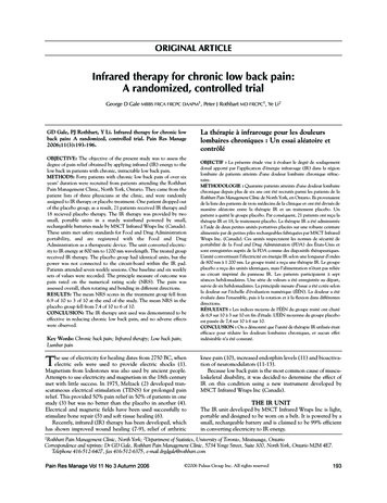
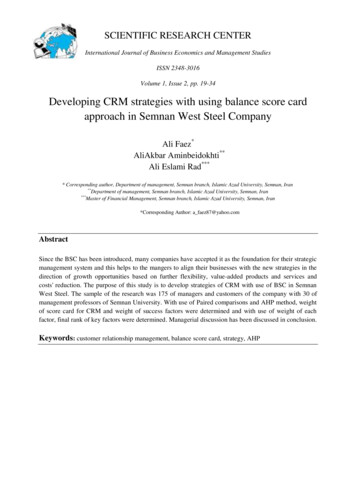
The effective length of the T-stub for elastic behaviour is assumedleff ,ini 0,85 leff(21)and n is taken equal to 1,25 m for simplification, see [7]. The boundary is represented as thelimiting bolt lengthLb ,lim 8,82 m3 Asleff t 3(22)The above estimation of the boundary introduced an error into the prediction of thestiffness coefficient. The accuracy of the simplified approach is shown in the Figures 4b, 4c,and 4d. Three calculations with the T-stub are presented. The T-stub characteristics are leff 458,333 mm, As 480 mm², m 50 mm and Lb 150 mm (short anchor bolts, Figure 4b),Lb 300 mm (moderate anchor bolts, Figure 4c), Lb 600 mm (long anchor bolts, Figure4d), while the n/m ratio takes the following values: 0,5; 1,0; 1,5 and 2,0.The boundary between "prying" and "no prying" is computed by means of formulae (20)and (22) for the theoretical and simplified models respectively.Figure 4a: T-stub dimensions27
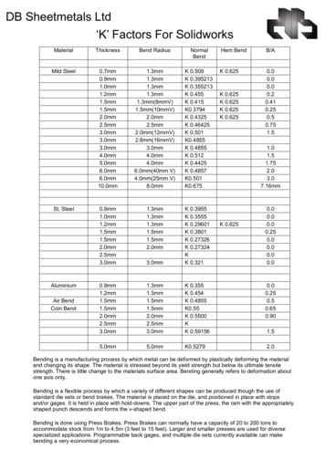
Figure 4b: Comparison between the theoretical and simplified models of the stiffness coefficient of theT-stub for variable thickness ratio t / m, Lb 150 mm28
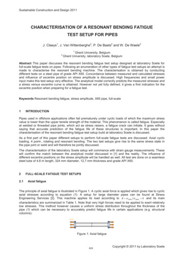
Figure 4c: Comparison between the theoretical and simplified models of the stiffness coefficient of theT-stub for variable thickness ratio t / m, Lb 300 mm29
Figure 4d: Comparison between the theoretical and simplified models of the stiffness coefficient ofthe T-stub for variable thickness ratio t / m, Lb 600 mm30
3Stiffness coefficientsThe component method adopted in Eurocode 3 [4] allows the prediction of the base platestiffness. The boundary is given by3As leff ,ini t Lb 8, 82 m3(23)When the above condition is satisfied, contact will occur and prying forces will develop.However, it is assumed the components are independent in this case, see [7], and thestiffness coefficients of the components arek p ,EC 3 leff ,ini t 3m3 0,85 leff t 3m3Akb ,EC 3 1,6 sLb(24)(25)When there is no prying, the condition (23) changes to3As leff ,ini t Lb 8, 82 m3k p ,* kb ,* FpE δpFpE δb (26)leff ,ini t 32m3 0, 425 leff t 3m3A 2,0 sLb(27)(28)The stiffness coefficient of the base plate in bending (24) or (27) and bolts in tension (25) or(28) should be composed into the stiffness coefficient of the T-stub111 kT kp ,i kb ,i(29)31
The influence of the washer plate on the deformation of base plate is studied in [8]. It isshown, that the stiffness is not influenced by an additional plate and the cover plate maybe neglected for the practical design.4Design ResistanceIn the Eurocode 3 [4], three collapse mechanisms of the T-stub are derived. These collapsemodes can be used for T-stubs in contact with the concrete foundation. The designresistance corresponding to the collapse modes is the following:Mode 3 - bolt fracture, see Figure 5a,F3, Rd Bt , Rd(30)Mode 1 - plastic mechanism of the plate, see Figure 5b,F1, Rd 4 leff mpl , Rdm(31)Mode 2 - mixed failure of the bolts and the plate, see Figure 5c,F2, Rd 2 leff mpl , Rd Bt , Rd nm nFigure 5: Failure modes of the T-stub32(32)
The design resistance FRd of the T-stub is derived as the smallest value obtained from theexpressions (30) to (32)FRd min(F1, Rd , F2, Rd , F3, Rd )(33)In case when there is no contact of the T-stub and the concrete foundation the failureresults either from the anchor bolts in tension (Mode 3) or from yielding of the plate inbending, see Figure 6. However, the collapse mode is different from the plastic mechanismof the plate with contact (Mode 1) and only two hinges develop in the T-stub. This failureis not likely to appear in the beam-to-column joints and beam splices because of the smalldeformation of the bolts in tension. This particular failure mode is named Mode 1*, seeFigure 6.Figure 6: The Mode 1* failureFigure 7: The design resistance of the T-stub33
The resistance corresponding to Mode 1* isF1*,Fd 2 leff mpl , Rdm(34)Large base plate deformation can be observed the Mode 1 * failure, which may finallyresult in the contact between the concrete foundation and the edges of the T-stub, i.e. in theprying forces. Further loads may therefore be applied to the T-stub until failure is obtainedthrough Mode I or Mode 2. However, to reach these collapse modes, large deformations ofthe T-stub are observed, which is not acceptable for the design. The additional resistancewhich arises between Mode 1 * and Mode 1 or Mode 2, see Figure 7, is thereforedisregarded and formula (34) is applied despite the discrepancy which could result fromthe comparisons with some experimental results [16].As a conclusion, the design resistance of the T-stub in cases when no prying forces developis taken equal toFRd min(F1*, Rd , F3, Rd ) .(35)The influence of cover plate used for strengthening of the base plate may be considered [4].It is applicable to the collapse mode I where the bending moment resistance of the coverplate is introduced [9]F1, Rd leff ,1 (4 mpl , Rd 2 mbp , Rd )m,(36)wherembp , Rd 2tbpf y ,bp4 γ M0,andf y ,bp is the yield stress of the cover plate,tbp is the thickness of the cover plate.34(37)
5Effective Length of the T-stubTwo groups of yield line patterns called circular and non-circular yield lines aredistinguished in Eurocode 3 [4], see Figure 8a. The major difference between circular andnon-circular patterns is related to contact between the T-stub and rigid foundation. Thecontact may occur only for non-circular patterns and prying force will develop only in thiscase. This is considered in the failure modes as follows:Mode 1The prying force does not have influence on the failure and development of plastic hingesin the base plate. Therefore, the formula (31) applies to both circular and non-circular yieldline patterns.Mode 2First plastic hinge forms at the web of the T-stub. Plastic mechanism is developed in thebase plate and its edges come into contact with the concrete foundation. As a result, pryingforces develop in the anchor bolts and bolt fracture is observed. Therefore, Mode 2 occursonly for non-circular yield line patterns, which allow development of prying forces.Mode 3This mode does not involve any yielding of the plate and applies therefore to any T-stub.In the design procedure, the appropriate effective length of the T-stub should be usedfor Mode 1: leff ,1 min( leff ,cp ; leff ,np )(38)for Mode 2: leff ,2 leff ,np(39)and the design resistance of the T-stub is given by the formula (33).a) Circular pattern, leff ,cpb) Non-circular pattern, leff ,npFigure 8: The yield line patterns35
Concerning Mode 1* failure, both circular and non-circular patterns have to be taken intoconsideration. Tables 1 and 2 indicate the values of leff for typical base plates in cases withand without contact. See Figures 9 and 10 for the used symbols.6Anchor BoltsThe following anchor bolt types represent commonly used fixing to the concretefoundation: hooked bars for light anchoring, cast-in-place headed anchors and anchorsbonded to drilled holes, see Figure 11. When it is necessary to transfer a big force, moreTable 1: The effective length leff of a T-stub of the base plate with two bolts inside the flangesPrying caseNo prying casel1 2 α m (4 m 1, 25 e)l1 2 α m (4 m 1, 25 e)l2 2 π ml2 4 π mleff ,1 min(l1 ; l2 )leff ,1 min(l1 ; l2 )leff ,2 l1leff ,2 l1Table 2: Effective length leff of a T-stub of base plate with for boltsPrying caseNo prying casel1 4 mx 1, 25 exl1 4 mx 1, 25 exl2 2 π mxl2 2 π mxl3 0, 5 bpl3 0, 5 bpl4 0, 5 w 2 mx 0,625 exl4 0, 5 w 2 mx 0,625 exl5 e 2 mx 0, 625 exl5 e 2 mx 0, 625 exl6 π mx 2 el6 π mx 4 el7 π mx pl7 2( π mx p)leff ,1 min(l1 ; l2 ; l3 ; l4 ; l5 ; l6 ; l7 )leff ,1 min(l1 ; l2 ; l3 ; l4 ; l5 ; l6 ; l7 )leff ,2 min(l1 ; l3 ; l4 ; l5 )leff ,2 min(l1 ; l3 ; l4 ; l5 )36
Figure 9: The effective length leff ofFigure 10: The effective length leff of a T-stub ofa T-stub of the base plate with two boltsthe base plate with four boltsFigure 11: Basic types of anchoring; a) cast-in-place, b) undercut, c) adhesive, d) grouted, e)expansion, f) anchoring to grillage beamsexpensive anchoring systems such as grillage beams embedded in concrete are designed.The models of the design resistance of the anchoring compatible with Eurocode have beenprepared for the short anchoring used in concrete structures [12] and are also applicable tolong anchors used for steel structures.The resistance of the anchoring is based on the ultimate limit state concept. The collapse ofanchoring (pullout of the anchor, failure of the concrete, .) should be avoided and collapseof anchor bolts is preferred. This avoids brittle failure of the anchoring. For seismic areas,the failure of the column base should occur in the base plate rather than in the anchor bolts[13]. The plastic mechanism in the plate ensures ductile behaviour and dissipation onenergy.For a single anchor, the following failure modes have to be considered: The pull-out failure N p , Rd , The concrete cone failure N c , Rd , The splitting failure of the concrete N sp , Rd .37
Similar verification is required for group of anchor bolts.The detailed description of the formulas for design resistance of various types of fasteningis included in the CEB Guide [12]. For calculation of the anchoring resistance, thetolerances of the bolt position recommended in standard [14] should be taken into accountaccording to Eurocode 3 [4]. This makes the prediction of resistance and stiffness morecomplicated which is not convenient in the practical design. The study [9] shows smallsensitivity of predicted stiffness and resistance to bolt tolerances.In case of embedded anchor bolts, the effective length of the bolt Lb consists of the freelength Lbf and effective embedded length Lb Lbf Lbe , see Figure 12.Figure 12: The effective length of the anchor boltThe headed anchor bolt can be used as a reference for modelling of the embedded anchorbolts that are used in steel structures. The deformation of the anchor bolt δ consists fromelongation of the bolt δb , deformation of the concrete cone δc and elongation due to bolthead deformation δ h .δ δb δc δh .(40)The prediction of the bolt deformation can be simplified taking into account only the boltelongation. The prediction of embedded length of typical anchor bolts is based onassumption of the distribution of the bond stress [15]. The relative displacement δ betweenthe surface of the concrete foundation and the embedded bar subjected to tensile force hasbeen observed experimentally [11]. Based on these experimental observations, the distanceLt , at which the tensile stress in the bolt decreases to zero can be approximated to 24 d. Inthe calculations of the stiffness properties of the anchor bolts in tension, constant stress in38
the bolt σ is assumed on the embedded length Lbe , see Figure 13b). The deformation of thebolt δ is expressed asδ BLbe.E As(41)When σbx designates the bond stress between the concrete and the embedded bolt, theaxialstress σ along the bar is equal toxσx σ 04σbxdx ,d(42)Figure 13: Bond stress distribution for long embedded barThe stress in the bolt of length Lem isσ Lt 04σbxdx .d(43)Substituting the strain ε x σx / E , the following can be obtained39
E εx Lt 04σbxdx .d(44)andδ Lt4Lt Lt εx dx d E σbx dx2(45)0 x0When σbx is constant and independent of x, see Figure 13b, the elongation of the bolt isδ 2 σb L2emdE(46)Assume the length Lem is proportional to the bolt diameter d and the length Lt 24 d , thenσb σd4 Lt(47)and the elongation of the bolt at the concrete surface isδ 2 σb L2em 2 σ d Lem σ Lem ,4 d Lt E2EdEF Lδ b t ,EA(48)(49)finallyLLbe em 12 d .3(50)When linear distribution of the bond stress is assumed as shown in Figure 14, the boltelongation is equal toδ 402 σb 0 L2em3dE(51)
Figure 14: Linear model of bondFigure 15: Non-linear distributionstress for long embedded barof the bond stressIn case of the elongation b' is proportional to the bolt diameter dσb 0 σd,2 Lem(52)it is possible to express the effective embedded length24 dLLbe em 8d33(53)Non-linear distribution of the bond stress using cubic parabola is assumed, see Figure 15,and the shape can be estimated byδ 2 σb 0 L2t5dE(54)The equation can be rewritten assuming 0 proportional to d for conservative value of theeffective embedded length24 dLLbe t 4,8 d .55(55)41
Analytical prediction of the elongation of embedded anchor bolts is sensitive toassumption of the distribution of the bond stress along the anchor bolt. The FE sensitivitystudy was focused on influence of the length of the anchor bolt and the headed plate onelastic deformations at the concrete surface, see Figure 16. The sensitivity study was basedon experiments [16] and [17]. Node to surface contact elements are used for modelling ofthe bond stress.Based on this study, the effective embedded length of bolts with regular surface can bepredicted as Lbe 8 d . The stress is developed on length equal to 24 d, which may beexpected as a boundary length of the anchoring by long bolts. This length is reduced by theheaded plate. The anchor bolt area can be taken as the net area As to simplify the design.Figure 16: A quarter of FE mesh for simulation of the anchor bolt, see test [16], bolt isconnected by node to surface contact elements, development of bond stress7ValidationSpecial set of experiments with components was carried out at Czech Technical Universityin Prague to evaluate a prediction of its behaviour, see [16] and [17]. In total, 4 pull-outtests with M24 embedded anchor bolts were performed, see Figures 17 and 18. The onlyvariable for these tests was the concrete quality of the foundation. For all the tests, thecollapse of the thread was observed. The tests show good agreement with the proposedmodel for the anchor bolt stiffness.42
Figure 17: Comparison of the proposed model to experiments with the anchor bolts [17], fck 40,1MPaFigure 18: Comparison of the proposed model to experiments with the anchor bolts [16], fck 33,3MPaThe experimental programme with T-stubs in tension consists of twelve tests [16]. It wasfocused on evaluation of prying effect and resistance and stiffness of the T-stub. For thispurpose, the base plate thickness and the bolt pitch were the variable parameters, the othercharacteristics were constant for all specimens. Six specimens with thick base plate (t 20mm) and six with thin base plate (t 12 mm) were tested. The bolt pitch 110 mm, 140 mmand 170 mm was used for both plate thickness resulting in dimension of the T-stub m 32,52 and 67 mm, n 40 mm, see Figure 19. The same M24 anchor bolts and concretefoundation 550 x 550 x 550 mm as in pull-out tests W13 / W14 were used, see Figure 18.43
Figure 19: The test specimen for the experiments with the T-stubThe pictures show the test results of the T-stub with the bolt pitch 110 mm and thedifferent base plate thickness. The comparison of the complex and simplified calculationsto the experimental results is included. The calculated resistance of specimens with the thinbase plate is the same for both models and is in good agreement with the experiments seeFigure 21. The combination of the plate mechanism and breaking of the anchor boltscaused the collapse of both specimens, which corresponds to Mode 2 of the design model.The resistance predicted for the specimens W97-01 and W97-02 (thick base plate) isdifferent for complex and simplified models, see Figure 20. According to the simplifiedmodel, there is prying of anchor bolts, which results in higher resistance. The complexmodel predicts no prying of the anchor bolts, which corresponds to the experimentalobservations. There were no plastic hinges observed in the base plate during theexperiment and the resistance of anchor bolts limits the resistance of the T-stub. However,the collapse was not reached because of the limitation of the load cell. The predictedstiffness is in a good agreement for all tests.Four tests with increased bolt pitch were performed, see Figures 22 and 23. The prying ofthe anchor bolts occurred for specimens with thin and thick base plates, which waspredicted by complex and simplified prediction models. There is good agreement betweenthe experimental and calculated resistances and stiffness.44
Development of two plastic hinges in the base plate of the specimens W97-03 and W97-04(with thick base plate) was observed during the experiment see Figure 22, but the anchorbolts of the specimens finally collapsed. The specimens with thin base plate collapsedwhen four plastic hinges created in the base plate. However, the testing was stoppedbecause large uplift (about 8 mm) was achieved. The experiment W97-07, see Figure 23,was interrupted by splitting failure of plain concrete block.The last four specimens with the largest bolt pitch 170 mm performed similar behaviourduring the test. High influence of prying of the anchor bolts was observed, which lead toFigure 20: The load deflection diagram of experiments W97-01 and W97-02, plate thickness 20 mmFigure 21: The load deflection diagram of experiments W97-05 and W97-06, plate thickness 12 mm45
combined collapse of the anchor bolts and the yielding of the base plate where four plastichinges created. There was only difference on deformation capacity of the T-stubs. Thespecimens W97 -11 and W97 -12 with thick base plate, see Figure 24, allowed uplift about 9mm followed by collapse of anchor bolts. The specimen W97 -09 collapsed by splittingfailure of plain concrete block, collapse ofW97-10 was not reached, see Figure 25. However,the uplift of both specimens was about 20 mm. The bending and the bearing of the anchorbolts were also observed at the extremely high deformations but it did not have aninfluence on the collapse.Figure 22: The load deflection diagram of experiments W97-03 and W97-04, plate thickness 20 mmFigure 23: The load deflection diagram of experiments W97-07 and W97-08, plate thickness 12 mm46
8Conclusions The paper describes the background of model behaviour of the basic components ofcolumn bases: the base plate in bending and the anchor bolts in tension. Thecomponent method for prediction of stiffness and resistance of the column basesloaded by an axial force and a bending moment was implemented into the Eurocode3 during the conversion from ENV document into EN document, see [19].Figure 24: The load deflection diagram of experiments W97-11 and W97-12, plate thickness 20 mmFigure 25: The load deflection diagram of experiments W97-09 and W97-10, plate thickness 12 mm47
Length of the bolts in the T-stub is the major difference between T-stubs representingthe base plates and T-stubs for end plates of beam to column connections. The boundary of behaviour of the T-stub with and without contact of the base plateand the concrete surface can be predicted by simple analytical model with goodaccuracy. The resistance and stiffness of the component is calculated for both cases bycomplex and simplified models. The accuracy of the simplified model is shown onthe comparison to the complex model and verified on the tests. The effective embedded length of the anchor bolt is the most important parameter forthe base plate stiffness prediction. The effective length can be estimated as Lbe 8 dfor typical embedded anchor bolts with regular bolt surface.AcknowledgementWithin the framework of the European Project COST C1 (Semi-rigid behaviour of civilengineering structural connections) and the Technical Committee 10 of ECCS (Europeanconvention for constructional steelwork) an ad-hoc working group prepared a backgrounddocument for Eurocode 3. Members of this group were: D. Brown, SCI London; A.M.Gresnigt, TU Delft; J.P. Jaspart, University of Liege; Z. Sokol, CTU in Prague; J.W.B. Stark,TU Delft; C.M. Steenhuis, TU Eindhoven; J.C. Taylor, SCI London; F. Wald, CTU in Prague(Convenor of the group) and K. Weynand, RTWH Aachen. The work at this contributionhas been supported by grant MSM 6840770005.References[1] Treiberg, T.: Pelarfot, Base Plates, in Swedish, Staalbyggnadsinstitutet, Pub. 101,Stockholm 1987.[2] Akiyama H.: Seismic Design of Steel Column for Architecture. in Japanese, Gibodoskupan,Tokyo 1985.[3] Melchers R. E.: Modelling of Column-Base Behaviour. In Connections in Steel Structures,Behaviour, Strength and Design, Proceedings, ed. Bjorhovde R., Brozzetti J., Colson A.,Elsevier Applied Science, London 1987, pp. 150-157.[4] Eurocode 3, ENV -1993-1-1, Design of Steel Structures -General Rules and Rules forBuildings. CEN, Brussels 1992; including Part 1.1, A2: Design of Steel Structures- GeneralRules and Rules for Buildings, Annex J, European Pre-norm, CEN, Brussels 1998.[5] Zoetemeijer, P.: Summary of the Researches on Bolted Beam-to-Column Connections. Report6-85-7, University of Technology, Delft 1985.48
[6] Yee, Y. L., Melchers, R. E.: Moment Rotation Curves for Bolted Connections. Journal of theStructural Division, ASCE, Vol. 112, ST3, pp. 615-635, March 1986.[7] Jaspart, J. P.: Etude de la semi-rigidité des noeuds poutre-colonne et son influence sur larésistance et la stabilité des ossatures en acier. in French, Ph.D. Thesis, Department MSM,University of Liege 1991.[8] Column Bases in Steel Building Frames, COST C1, ed. K. Weynand, Brussels 1999.[9] Wald F.: Patky sloupů -Column Bases, ČVUT, Prague 1995, ISBN 80-01-01337-5.[10] Owens G. W., Cheal B. D.: Structural Steelwork Connections. Butterworths, London 1988.[11] Wald F., Obata M., Matsuura S., Goto Y.: Prying of Anchor Bolts. Nagoya UniversityReport, Nagoya 1993, pp. 241 -249.[12] Fastenings to Concrete and Masonry Structures. State of the Art Report, CEB, ThomasTelford Services Ltd., London 1994, ISBN 0 7277 19378.[13] Astaneh A., Bergsma G., Shen J .R.: Behavior and Design of Base Plates for Gravity,Wind and Seismic Loads. in Proceedings AISC, National Steel Construction Conference,Las Vegas 1992.[14] ENV 1090-1, Execution of Steel Structures, Part 1 -General Rules and Rules for Buildings,CEN, Brussels 1997.[15] Salmon C. G., Schenker L., Johnston G. J.: Moment -Rotation Characteristics of ColumnAnchorages. Transaction ASCE, 1957, Vol. 122, No.5, pp. 132 -154.[16] Sokol Z., Wald F.: Experiments with T-stubs in Tension and Compression. Research Report,ČVUT, Prague 1997.[17] Wald F., Šimek I., Sokol Z., Seifert J.: The Column-Base Stiffness Tests. in Proceedings ofthe Second State of the Art Workshop COST Cl, ed. Wald F., Brussels 1994, pp. 281-292.[18] Sokol Z., Ádány S., Dunai L., Wald F.: Column Base Finite Element Modelling. ActaPolytechnica, Vol. 39, No.5, Praha 1999, ISSN 1210-2709.[19] prEN 1993-1-8: 2004. Eurocode 3: Design of Steel Structures, Part 1.8: Design of joints,European Standard, CEN, Brussels, 2004.Notationathickness of the fillet weldddiameter of the boltfyyield stress of steelkstiffness coefficientmdistance from the bolt axes to the weld edge49
mplbending resistance of base platendistance from the bolt axes t
The influence of the washer plate on the deformation of base plate is studied in [8]. It is shown, that the stiffness is not influenced by an additional plate and the cover plate may be neglected for the practical design. 4 Design Resistance In the Eurocode 3 [4], three collapse mechanisms of the T-stub are derived. These collapse