Transcription
Remote I/O AdapterModuleCatalog Number 1747-ASBUser Manual
Important User InformationBecause of the variety of uses for the products described in thispublication, those responsible for the application and use of theseproducts must satisfy themselves that all necessary steps have beentaken to assure that each application and use meets all performanceand safety requirements, including any applicable laws, regulations,codes and standards. In no event will Rockwell Automation beresponsible or liable for indirect or consequential damage resultingfrom the use or application of these products.Any illustrations, charts, sample programs, and layout examplesshown in this publication are intended solely for purposes ofexample. Since there are many variables and requirements associatedwith any particular installation, Rockwell Automation does not assumeresponsibility or liability (to include intellectual property liability) foractual use based upon the examples shown in this publication.Allen-Bradley publication SGI-1.1, Safety Guidelines for theApplication, Installation and Maintenance of Solid-State Control(available from your local Rockwell Automation office), describessome important differences between solid-state equipment andelectromechanical devices that should be taken into considerationwhen applying products such as those described in this publication.Reproduction of the contents of this copyrighted publication, in wholeor part, without written permission of Rockwell Automation, isprohibited.Throughout this publication, notes may be used to make you aware ofsafety considerations. The following annotations and theiraccompanying statements help you to identify a potential hazard,avoid a potential hazard, and recognize the consequences of apotential hazard:WARNING!ATTENTION!IMPORTANTIdentifies information about practices orcircumstances that can cause an explosion in ahazardous environment, which may lead to personalinjury or death, property damage, or economic loss.Identifies information about practices orcircumstances that can lead to personal injury ordeath, property damage, or economic loss.Identifies information that is critical for successfulapplication and understanding of the product.Allen-Bradley is a trademark of Rockwell Automation
Summary of ChangesSummary of ChangesThe information below summarizes the changes to this manual sincethe last printing as Publication 1747-6.13 - December 1996.To help you find new information and updated information in thisrelease of the manual, we have included change bars as shown to theright of this paragraph.New Information1For This New InformationSee PageUpdated table of compatible scanners1-9Updated table of compatible RIO adapters1-9Updated list of compatible modules1-10Added primary/complementary chassisinformation for SW22-3Clarified DIP SW setting4-5C-Tick certificationA-1Publication 1747-UM006B-EN-P - June 2003
2Summary of ChangesPublication 1747-UM006B-EN-P - June 2003
Table of ContentsPrefaceWho Should Use this Manual- . . . . . . . . . . . . . . .Purpose of this Manual . . . . . . . . . . . . . . . . . . . .Contents of this Manual . . . . . . . . . . . . . . . . .Related Documentation . . . . . . . . . . . . . . . . .Terms and Abbreviations. . . . . . . . . . . . . . . . . . .Common Techniques Used in this Manual . . . . . .Rockwell Automation Support . . . . . . . . . . . . . . .Your Questions or Comments on this Manual .11123566Chapter 1Overview1747-ASB Module Overview . . . . . . . . . . . . . . . . . . . . . . . 1-1Remote I/O Overview . . . . . . . . . . . . . . . . . . . . . . . . . . . . 1-2How The Scanner Interacts With Adapters . . . . . . . . . . 1-2Scanner I/O Image Division . . . . . . . . . . . . . . . . . . . . . 1-4Crossing Logical Rack Boundaries. . . . . . . . . . . . . . . . . 1-4Creating More Than One Logical Device byCrossing a Logical Rack Boundary . . . . . . . . . . . . . . . 1-5Transferring Data With RIO Discrete and Block Transfers 1-6RIO Discrete Transfer Example. . . . . . . . . . . . . . . . . . . 1-7Physical and Logical RIO Link Specifications . . . . . . . . . 1-8Extended Node Capability . . . . . . . . . . . . . . . . . . . . . . 1-8Compatible RIO Scanners. . . . . . . . . . . . . . . . . . . . . . . 1-9Compatible RIO Adapters . . . . . . . . . . . . . . . . . . . . . . . . . 1-9Compatible Modules . . . . . . . . . . . . . . . . . . . . . . . . . . . . . 1-101747-ASB Module Feature . . . . . . . . . . . . . . . . . . . . . . . . . 1-10Hardware Features. . . . . . . . . . . . . . . . . . . . . . . . . . . . 1-11Status Display and LEDs. . . . . . . . . . . . . . . . . . . . . . . . 1-11DIP Switches . . . . . . . . . . . . . . . . . . . . . . . . . . . . . . . . 1-11RIO Link and Processor Restart Lockout Connector . . . . 1-13Door Label . . . . . . . . . . . . . . . . . . . . . . . . . . . . . . . . . 1-13Self-Locking Tabs. . . . . . . . . . . . . . . . . . . . . . . . . . . . . 1-13Cable Tie Slots. . . . . . . . . . . . . . . . . . . . . . . . . . . . . . . 1-13Chapter 2Quick Start for Experienced Users Required Tools and Equipment . . . . . . . . . . . . . . . . . . . . . 2-1Procedures .SW1 . . .SW2 . . .SW3 . . .i.2-22-32-32-3Publication 1747-UM006B-EN-P - June 2003
iiTable of ContentsChapter 3AddressingChassis Overview . . . . . . . . . . . . . . . . . . . . . . . . .Slot Numbering. . . . . . . . . . . . . . . . . . . . . . . . . . .Addressing I/O Modules . . . . . . . . . . . . . . . . . . . .2-Slot Addressing . . . . . . . . . . . . . . . . . . . . . . .2-Slot Addressing Considerations . . . . . . . . . . .2-Slot Addressing Examples . . . . . . . . . . . . . . .1-Slot Addressing . . . . . . . . . . . . . . . . . . . . . . .1-Slot Addressing Considerations . . . . . . . . . . .1-Slot Addressing Examples . . . . . . . . . . . . . . .1/2-Slot Addressing . . . . . . . . . . . . . . . . . . . . .1/2-Slot Addressing Considerations . . . . . . . . . .1/2-Slot Addressing Examples. . . . . . . . . . . . . .How I/O Module Images Are Mapped . . . . . . . . . .How Discrete I/O Modules Are Mapped . . . . . .How Specialty I/O Module Images Are MappedWhen Block Transfer Mode is Selected . . . . . . .When Discrete Mode is Selected. . . . . . . . . . . 143-143-15Chapter 4ConfigurationPublication 1747-UM006B-EN-P - June 2003DIP Switch Information . . . . . . . . . . . . . . . . . . . . . . . . . . . 4-1DIP Switch SW1. . . . . . . . . . . . . . . . . . . . . . . . . . . . . . 4-2Logical Group Number (SW1-7,8) . . . . . . . . . . . . . . . . . 4-4DIP Switch SW2. . . . . . . . . . . . . . . . . . . . . . . . . . . . . . 4-4Primary/Complementary Chassis (SW2-3) . . . . . . . . . . . 4-5Reserved (SW2-4) . . . . . . . . . . . . . . . . . . . . . . . . . . . . 4-9Special Image and Chassis Size Considerations . . . . . . . . . . 4-13Not Enough 1747-ASB Module Image to Map All of theAvailable Slots . . . . . . . . . . . . . . . . . . . . . . . . . . . . . . . 4-131747-ASB Image Size Exceeds Slot Requirements. . . . . . 4-14One Slot of Pair is Present, and 1747-ASB Module Image isAvailable for Both Slots . . . . . . . . . . . . . . . . . . . . . . . . 4-14Both Slots Of A Pair Are Available But There Is Only Enough1747-ASB Module Image Space Available For One Slot . 4-15DIP Switch SW3. . . . . . . . . . . . . . . . . . . . . . . . . . . . . . 4-15Processor Restart Lockout (SW3-2) . . . . . . . . . . . . . . . . 4-17Addressing Mode (SW3-5,6) . . . . . . . . . . . . . . . . . . . . . 4-20Specialty I/O Mode (SW3-7) . . . . . . . . . . . . . . . . . . . . . 4-21I/O Module Keying (SW3-8) . . . . . . . . . . . . . . . . . . . . . 4-21Switch Setting Summary . . . . . . . . . . . . . . . . . . . . . . . . . . 4-22SW2 . . . . . . . . . . . . . . . . . . . . . . . . . . . . . . . . . . . . . . 4-22SW3 . . . . . . . . . . . . . . . . . . . . . . . . . . . . . . . . . . . . . . 4-23
Table of ContentsiiiChapter 5Installation and WiringEuropean Union Direct Compliance. . . . . .EMC Directive . . . . . . . . . . . . . . . . . . .Installing the1747-ASB Module . . . . . . . . .Link Wiring. . . . . . . . . . . . . . . . . . . . . . . .Correct Link Wiring . . . . . . . . . . . . . . .Incorrect Link Wiring . . . . . . . . . . . . . .Link Termination . . . . . . . . . . . . . . . . .Wiring a Processor Restart Lockout Switch .I/O Module Addressing Labels. . . . . . . . . .Using a PLC as a Master . . . . . . . . . . . .Using an SLC as a Master . . . . . . . . . . .Octal Label Kit Installation. . . . . . . . . . . . .Applying the Octal Filter Label . . . . . . .Applying the Octal Door Label . . . . . . .Octal Kit and I/O Module Information em Start-Up. . . . . . . . . . . . . . . . . . . . . . . . . . . . . . . .Powerup and Initialization Sequences . . . . . . . . . . . . . . .Save Mode. . . . . . . . . . . . . . . . . . . . . . . . . . . . . . . . .Check Mode . . . . . . . . . . . . . . . . . . . . . . . . . . . . . . .Normal Operation . . . . . . . . . . . . . . . . . . . . . . . . . . . . . .Communication Exception . . . . . . . . . . . . . . . . . . . . . . .Inhibit Condition . . . . . . . . . . . . . . . . . . . . . . . . . . . .Remote Expansion Chassis Power Loss . . . . . . . . . . . . . .Invalid RIO Link Transfers . . . . . . . . . . . . . . . . . . . . . . . .RIO Discrete or Block Transfers To Empty orNonexistent Chassis Slots . . . . . . . . . . . . . . . . . . . . .RIO Discrete Transfers To Block Transfer Chassis SlotsRIO Block Transfers To Discrete Chassis Slots . . . . . . .Invalid Length RIO Block Transfers. . . . . . . . . . . . . . .Testing the 1747-ASB Module . . . . . . . . . . . . . . . . . . . . .I/O Module Insertion into a Slot . . . . . . . . . . . . . . . . .I/O Module Removal from a Scanned Slot. . . . . . . . . .I/O Module Removal from an Unscanned Slot. . . . . . 6-10Troubleshooting Introduction . . . . . . . . . . . . . . . . . . . . . .Contacting Rockwell Automation . . . . . . . . . . . . . . . . . . . .Status Operating Codes for Normal Operating Conditions . .Error Codes for Error Conditions . . . . . . . . . . . . . . . . . . . .DIP Switch Configuration Mismatch Fault Codes - Codes1 and 2 . . . . . . . . . . . . . . . . . . . . . . . . . . . . . . . . . . . .7-17-27-27-3Chapter 6Start-Up and OperationChapter 7Troubleshooting7-5Publication 1747-UM006B-EN-P - June 2003
ivTable of ContentsI/O Module Configuration MismatchFault Codes - Code 3 . . . . . . . . . . . . . . . . . . . . . . . . . . 7-7I/O Runtime Fault Codes - Code 4 . . . . . . . . . . . . . . . . 7-8Chapter 8Application ExamplesBasic SLC 500 Example Using and RIO ScannerRIO Device Configuration . . . . . . . . . . . . .SLC Processor Image . . . . . . . . . . . . . . . . .1747-ASB Module Configuration Details . . .1747-ASB Module I/O Mapping Details. . . .RIO Address Label Examples . . . . . . . . . . .Application Example Program . . . . . . . . . .Basic SLC 500 Example Using and RIO ScannerRIO Device Configuration . . . . . . . . . . . . .SLC Processor Image . . . . . . . . . . . . . . . . .1747-ASB Module 1 Configuration Details . .1747-ASB Module 2 Configuration Details . .1747-ASB Module 1 I/O Mapping Details . .1747-ASB Module 2 I/O Mapping Details . .RIO Address Label Examples . . . . . . . . . . .Application Example Program . . . . . . . . . .PLC-5 Example . . . . . . . . . . . . . . . . . . . . . . . .RIO Device Configuration . . . . . . . . . . . . .PLC Processor Image . . . . . . . . . . . . . . . . .1747-ASB Module 1 Configuration Details . .1747-ASB Module 2 Configuration Details . .1747-ASB Module 1 I/O Mapping Details . .1747-ASB Module 2 I/O Mapping Details . .RIO Address Label Examples . . . . . . . . . . .Application Example Program . . . . . . . . . .Appendix ASpecificationsAppendix BDifferences Between the1747-ASB Module and the1771-ASB Series C ModuleAppendix CDIP Switch and AddressConfiguration WorksheetsIndexPublication 1747-UM006B-EN-P - June 128-138-158-168-178-188-198-208-218-228-238-24
PrefaceRead this preface to familiarize yourself with the rest of the manual.This preface covers the following topics: Who Should Use thisManual-who should use this manualthe purpose of this manualterms and abbreviationsconventions used in this manualRockwell Automation supportUse this manual if you are responsible for designing, installing,programming, or troubleshooting control systems that useAllen-Bradley small logic controllers.You should have a basic understanding of PLC and SLC 500products. You should understand programmable controllers and beable to interpret the ladder logic instructions required to control yourapplication. If you do not, contact your local Allen-Bradley representative for information on available training courses beforeusing this product.Purpose of this ManualThis manual is a learning and reference guide for the remote I/Oadapter module. It describes the procedures you use to address,configure, install, and operate the 1747-ASB remote I/O adaptermodule.Contents of this ManualChapter1TitleContentsPrefaceDescribes the purpose, background, and scope ofthis manual. Also specifies the audience forwhom this manual is intended.1OverviewExplains and illustrates the theory behind the1747-ASB module's operation. Covers hardwareand software features, compatible devices, andsetup.2Quick Start forExperienced UsersServes as a Quick Start Guide for the 1747-ASBmodule.3AddressingGives a chassis overview, and explains slotnumbering, I/O module image mapping, 2-slot,1-slot, and 1/2-slot addressing.Publication 1747-UM006B-EN-P - June 2003
2Preface4ConfigurationContains DIP switch information, and shows oddsize chassis and image conditions.5Installation andWiringProvides installation procedures and wiringguidelines.6Start-up andOperationExplains powerup and initialization sequences,normal operation, communication exceptions,remote expansion power loss, invalid RIO linktransfers, and testing the 1747-ASB module.7TroubleshootingShows how to interpret and correct problemswith your 1747-ASB module.8Application ExamplesExamines both SLC 500 and PLC-5/40tapplications using a 1747-ASB module. Givesexamples of the ladder programming necessaryto achieve the described result.Appendix ASpecificationsContains 1747-ASB and RIO link specifications,as well as throughput information.Appendix BDifferences Betweenthe 1747-ASB and1771-ASB Series CModulesProvides a point-by-point comparison of the 1747and 1771 ASB modules.Appendix CWorksheetsContains worksheets for setting the 1747-ASBmodule's DIP switches and addressing remoteI/O modules with an SLC processor.Related DocumentationThe following documents contain additional information concerningAllen-Bradley SLCt and PLC products. To obtain a copy, contact yourlocal Allen-Bradley office or distributor.ForRead This DocumentDocumentNumberAn overview of the SLC 500 family of productsSLC 500 System Overview1747-SO001A description on how to install and use your ModularSLC 500 programmable controllerInstallation & Operation Manual for ModularHardware Style Programmable ControllersUser Manual1747-UM011Information regarding the use of a 1747-KE module as acommunications interfaceDH-485/RS-232C Interface Module UserManual1747-6.12Information regarding the use of the 1747-DCM as a remoteI/O deviceDirect Communication Module User Manual1747-6.8Publication 1747-UM006B-EN-P - June 2003
PrefaceInformation regarding the use of the 1747-SN SLC RIOscannerRIO Scanner User Manual1747-6.6Information regarding the use of analog modules with theSLC 500 systemSLC 500 Analog I/O Modules User Manual1746-6.4Information regarding programming your BASIC moduleSLC 500 BASIC Language Reference1746-RM001In-depth information on grounding and wiring Allen-Bradleyprogrammable controllersAllen-Bradley Programmable ControllerGrounding and Wiring Guidelines1770-4.1A description on how to install a PLC-5r systemPLC-5 Family Programmable ControllersHardware Installation Manual1785-6.6.1A description of important differences between solid-stateprogrammable controller products and hard-wiredelectromechanical devicesApplication Considerations for Solid-StateControlsSGI-1.1An article on wire sizes and types for grounding electricalequipmentNational Electrical CodePublished by theNational FireProtectionAssociation ofBoston, MA.A glossary of industrial automation terms and abbreviationsAllen-Bradley Industrial Automation GlossaryAG-7.13The following terms and abbreviations are specific to this product.For a complete listing of Allen-Bradley terminology, refer to theAllen-Bradley Industrial Automation Glossary, Publication NumberAG-7.1.Terms and AbbreviationsAdapter - Any physical device that is a slave on the RIO link.Adapter Image - That portion of the scanner image assigned to anindividual adapter. You configure the adapter image by assigning it astarting logical rack number, starting logical group number and thenumber of logical groups it uses. In the case of the 1747-ASB module,this is referred to as the 1747-ASB module image.ASB Module - The Catalog Number 1747-ASB Remote I/O AdapterModule. The 1747-ASB module is an adapter.ASB Module Chassis - The chassis directly controlled by the1747-ASB module. This includes the remote chassis and (if installed)two remote expansion chassis.Discrete I/O Module - An I/O module used to sense or controltwo-state (ON/OFF) devices.Inhibit - A function by which the scanner stops communicating witha logical device. The logical device will consider itself inhibited if itPublication 1747-UM006B-EN-P - June 2003
4Prefacedoes not receive communications from the scanner within a certainperiod of time.I/O Module - Any 1746 or 1747 I/O module that is supported by the1747-ASB module.Local Expansion Chassis - A chassis that is connected to a local SLCchassis using a 1747-C9 (91.4 cm [36 in.]) or 1747-C7 (15.2 cm [6 in.])cable.Local PLC Chassis - The 1771 chassis that contains a PLC processorand scanner.Local SLC Chassis - The chassis that contains the SLC processor andscanner.Logical Device - Any portion of a logical rack that is assigned to asingle adapter. Adapters may appear as more than one logical device.Logical Group - A logical group consists of one input and one outputword within a logical rack. A word consists of 16 bits, each bitrepresents one terminal on a discrete I/O module.Logical Rack - A fixed section of the scanner image comprised ofeight input words and eight output words.Logical Slot - A logical slot consists of one input and one output bytewithin a logical group. A byte consists of 8 bits, each bit representsone terminal on a discrete I/O module.PLC Chassis - A physical PLC rack that houses 1771 I/O modules andPLC processors.Remote Chassis - The chassis containing a 1747-ASB module andconnected to the local SLC or PLC chassis via the RIO link.Remote Expansion Chassis - A chassis that is connected to a remotechassis using a 1747-C9 (91.4 cm [36 in.]) or 1747-C7(15.2 cm [6 in.]) cable.Reset, Adapter Decide - Commands sent by the scanner to a logicaldevice during an RIO discrete transfer. These commands instruct thelogical device to reset all of its discrete outputs if hold last state is notselected, or to hold all of its discrete outputs in their last state if holdlast state is selected.Reset, Adapter Reset - Commands sent by the scanner to a logicaldevice during an RIO discrete transfer. These commands instruct thelogical device to reset all of its discrete outputs regardless of the holdlast state selection.Publication 1747-UM006B-EN-P - June 2003
Preface5RIO Block Transfer - The exchange of up to 64 words of databetween the scanner and adapter. RIO block transfers only occur ifyou program them in your processor control program. The 1747-ASBmodule supports a block transfer of up to 8 words.RIO Discrete Transfer - The exchange of image data between thescanner and adapter. RIO discrete transfers occur continuouslywhenever the scanner and adapter are communicating on the RIOlink.RIO Link - An Allen-Bradley communication system supportinghigh-speed serial transfer of Remote I/O (RIO) control information.This link consists of one master one or more slaves.Scanner - The communication master on the RIO link.Scanner Image - The data table area within the scanner, used toexchange I/O information between the scanner and all the adapterson the RIO link. The scanner image is a portion of the SLC or PLCprocessor image.SLC Chassis - A physical SLC rack that houses SLC processors, 1746and 1747 I/O modules.Slot - The physical location in any chassis used to insert I/O modules.Specialty I/O Module - An I/O module other than a discrete I/Omodule (e.g., an analog module).The following conventions are used throughout this manual:Common Techniques Usedin this Manual Bulleted lists such as this one provide information, notprocedural steps. Numbered lists provide sequential steps or hierarchicalinformation. Italic type is used for emphasis. Text in this font indicates words or phrases you should type.Allen-Bradley offers support services worldwide, with over 75Sales/Support Offices, 512 authorized Distributors and 260 authorizedSystems Integrators located throughout the United States alone, plusAllen-Bradley representatives in every major country in the world.Publication 1747-UM006B-EN-P - June 2003
6PrefaceRockwell AutomationSupportBefore you contact Rockwell Automation for technical assistance, wesuggest you please review the troubleshooting information containedin this publication first.If the problem persists, call your local Rockwell Automationrepresentative or contact Rockwell Automation in one of the 0.646.5800Outside UnitedStates/CanadaYou can access the phone number for yourcountry via the Internet:1. Go to http://www.ab.com2. Click on Product Support(http://support.automation.rockwell.com)3. Under Support Centers, click on ContactInformation 1. Go to http://www.ab.com2. Click on Product r Questions or Comments on this ManualIf you find a problem with this manual, please notify us of it.If you have any suggestions for how this manual could be made moreuseful to you, please contact us at the address below:Rockwell AutomationAutomation Control & Information GroupTechnical Communication, Dept. 602VP.O. Box 2086Milwaukee, WI 53201-208Publication 1747-UM006B-EN-P - June 2003
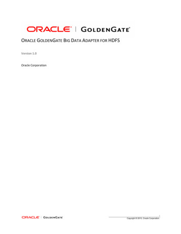
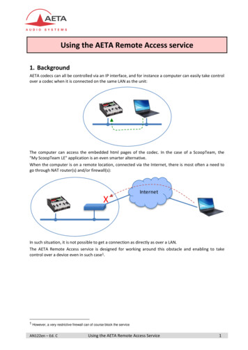
Chapter1OverviewThis chapter presents: 1747-ASB ModuleOverview1747-ASB module overviewremote I/O overviewcompatible devices1747-ASB module featuressetup and operational overviewThe 1747-ASB module is an SLC 500 single-slot, RIO communicationlink module. It occupies the first slot (slot 0) of a 1746 remote chassis,where the SLC processor normally resides.The 1747-ASB module is an adapter, or slave, on the RIO link, and themaster of the remote chassis and remote expansion chassis it isinstalled in. Remote expansion chassis are optional. It acts as agateway between the scanner and the I/O modules residing in theremote chassis and remote expansion chassis. The 1747-ASB modulemaps the image of the I/O modules in its remote chassis and remoteexpansion chassis directly to the SLC or PLC processor image.Output data is sent from the scanner of either the SLC or PLC localchassis to the 1747-ASB module across the RIO link. This data isautomatically transferred to the output modules across the chassisbackplane by the 1747-ASB module. Inputs from the input modulesare collected via the backplane by the 1747-ASB module and sentback to the scanner across the RIO link. No user programming of the1747-ASB module is necessary.1747-ASB ModuleSupervisory SLC (or PLC)Remote Chassis Remote Expansion ChassisRIO Link1747-ASB ModuleOutputs toModulesInputs toModulesRemote Chassis1747-ASB ModuleRemote Chassis1Remote Expansion ChassisPublication 1747-UM006B-EN-P - June 2003
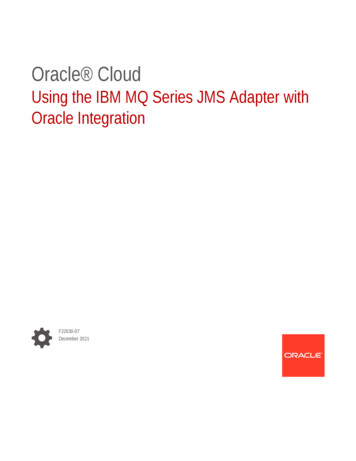
1-2OverviewTo better understand the use of the 1747-ASB module, you shouldhave an understanding of the RIO link. The RIO link is anAllen-Bradley communications system supporting high-speed transferof control information. An RIO link consists of a single master deviceand one or more slave devices. The master device is referred to as thescanner. The slave devices are referred to as adapters (such as the1747-ASB module).Remote I/O OverviewRIO scanners and adapters work together to serially communicate PLCor SLC processor data to remotely located I/O devices. PLC and SLCprocessors exchange inputs and outputs with scanners. Scannersexchange inputs and outputs with adapters located on the RIO link.The adapter's control is based on the adapter type.How The Scanner Interacts With AdaptersThe scanner's function is to continuously scan the adapters on the RIOlink in a consecutive manner. The scan consists of one or more RIOdiscrete transfers to each adapter on the RIO link.RIO discrete transfers consist of the scanner sending output imagedata and communication commands to the adapter that instruct theadapter on how to control its output. (These include run, reset,adapter reset, and reset decide commands.) The adapter responds bysending input data to the scanner. The scanner performs as many RIOdiscrete transfers as necessary to update the entire adapter image. IfRIO discrete transfers do not occur, data is not exchanged betweenthe scanner and adapter.IMPORTANTPublication 1747-UM006B-EN-P - June 2003RIO discrete transfers are asynchronous with theprocessor scan.
Overview1-31747-ASB ModuleProcessorScannerRIO DiscreteTransfers withAdapter 1Remote Chassis Remote Expansion ChassisSLC Local ChassisRIO LinkRIO DiscreteTransfers withAdapter 2RediPANEL1747-ASB ModuleRIO DiscreteTransfers withAdapter 3Remote Chassis Remote Expansion ChassisRIO DiscreteTransfers withAdapter 4RediPANEL1747-ASB ModuleProcessor/ScannerRIO DiscreteTransfers withAdapter 1PLC Local ChassisRIO LinkRemote Chassis Remote Expansion ChassisRIO DiscreteTransfers withAdapter 2RediPANEL1747-ASB ModuleRIO DiscreteTransfers withAdapter 3Remote Chassis Remote Expansion ChassisRIO DiscreteTransfers withAdapter 4Publication 1747-UM006B-EN-P - June 2003
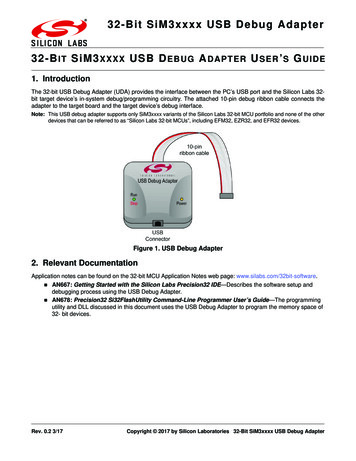
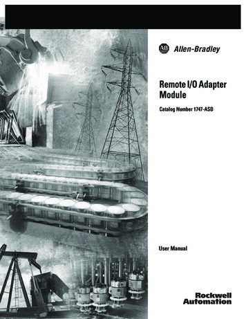
1-4OverviewScanner I/O Image DivisionThe scanner allows each adapter to use a fixed amount (user defined)of the scanner's input and output image. Part of the processor's imageis used by local I/O, the other portion is used by the scanner forremote I/O. For a PLC-5, logical rack 0 is dedicated for local I/O.The scanner's remote I/O image is divided into logical racks andfurther divided into logical groups. A full logical rack consists of eightinput and eight output image words. A logical group consists of oneinput and one output word in a logical rack. Each logical group isassigned a number from 0 to 7. The number of racks available forremote I/O depends on the scanner you are using.Local I/OLogical Rack 0Remote I/O(ScannerImage)Logical Rack 1Logical Rack 2Logical Rack 3Logical Group 0Logical Group 7Processor I/OImageScanner I/OImageAdapterImageThe scanner image also contains the image of each adapter on theRIO link. The adapter is assigned a portion of the scanner image,which is referred to as the adapter image.Crossing Logical Rack BoundariesAdapter image size is expressed in an even number of groups. Forexample, the 1747-ASB module image can be any size between 2logical groups and 32 logical groups (4 logical racks), in 2 logicalgroup increments.If the adapter's image size is greater than 8 logical groups, the imagecrosses logical rack boundaries. If an adapter's image size is less than8 logical groups, it too can cross a logical rack boundary dependingupon the starting logical group number. The significance of crossinglogical rack boundaries is discussed in the next section.Publication 1747-UM006B-EN-P - June 2003
OverviewScanner Input or Output ImageBit Number (Octal)Bit Number (Decimal)LogicalRack 0LogicalRack 11710 70158 70Group 0Group 1Group 2Group 3Group 4Group 5Group 6Group 7Group 0Group 1Group 2Group 3Group 4Group 5Group 6Group 7Scanner Input or Output ImageBit Number (Octal)Bit Number (Decimal)AdapterImageLogicalRack 0LogicalRack 1Adapter image is 12 logical groups in size andcrosses a logical rack boundary due to its size.IMPORTANT1-5Group 0Group 1Group 2Group 3Group 4Group 5Group 6Group 7Group 0Group 1Group 2Group 3Group 4Group 5Group 6Group 71710 70158 70AdapterImageAdapter image is 6 logical groups in size and crosses a logicalrack boundary due to its starting logical group number.Due to SLC and PLC addressing differences, whenthe 1747-ASB module is used with an SLC processor,the image bit numbers are 0 to 7, 8 to 15 decimal.When the 1747-ASB module is used with a PLCprocessor, the image bit numbers are 0 to 7, 10 to 17octal. The I/O image figures, like the two above,indicate the type of image bit numbers used (octal,decimal, or both) throughout this manual.Creating More Than One Logical Device by Crossing a LogicalRack BoundaryRIO discrete transfers occur on a logical device basis, not an adapterbasis. A logical device is any portion of a lo
Purpose of this Manual This manual is a learning and reference guide for the remote I/O adapter module. It describes the procedures you use to address, configure, install, and operate the 1747-ASB remote I/O adapter module. Contents of this Manual Chapter Title Contents Preface Describes the purpose, background, and scope of this manual.