Transcription
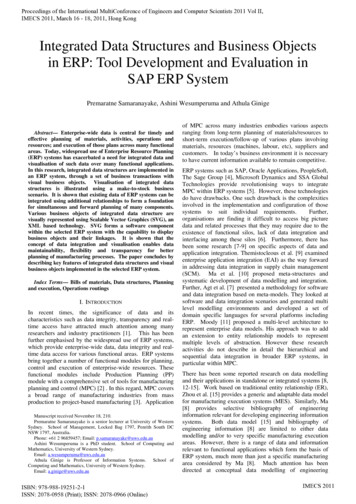
New Standards forBroadcast Structures ANSI/EIA/TIA-222-GJOHN WAHBA, PH.D., PEDAVID BRINKER, PE MARK MALOUF, PEJOHN ERICHSEN, PERadian Communication ServicesOakville, ON, CanadaRohn Industries, Inc.Peoria, ILValmont CommunicationsPlymouth, INABSTRACTThe next revision of the ANSI/TIA/EIA standard“Structural Standards for Steel Antenna Towers andAntenna Supporting Structures” will represent the mostdrastic change to the standard since its first publicationin 1949. This revision will change the loads and designcriteria for communication towers including broadcaststructures. It will also have an impact on the loadcarrying capacity of existing structures.The revised standard (Rev G) is scheduled for release in2003. The proposed changes will require an aggressivetraining schedule for all users of the standard. Theauthors of this paper who are members of he technicalreview committee for the TIA/EIA-222 standard willpresent in this paper the major changes proposed andalso explain how theses changes may affect broadcaststructures.INTRODUCTIONThis paper outlines the latest development regarding thenext revision of the ANSI/TIA/EIA-222. It is based onthe most recent proposals at the time of this writing.Subsequent revisions and additions may occur duringthe consensus verification process.DESIGN PHILOSOPHYThis proposed revision of the standard is based on limitstates design. The structures are checked for two majorlimit states (i) strength limit states and (ii) serviceabilitylimit states. The strength limit states ensures thatstructures are safe under extreme loading conditionswhile the serviceability limit states checks that thestructures is capable of providing the service undernormal conditions.ENVIROMENTAL LOADSMalouf Engineering Intl.Richardson, TXevent of failure. This classification is intended forstructures that are used for services that are optionaland /or where a delay in returning the services would beacceptable. Ice loading does not apply to this categoryof structures. The nominal 50-year return wind load isreduced using an importance factor to a nominal 25year return loading. Category II structures represent asubstantial hazard to human life and damage to propertyin the event of failure and are intended for services thatmay be provided by other means.Category IIstructures use nominal 50-year return wind and iceloads. Category III structures are essential facilities anduse nominal 100-year return loads determined usingappropriate importance factors applied to the nominal50-year return loads.Wind LoadsA load factor of 1.6 is applied to nominal wind loadsfor strength limit states design. A directionality factoris applied to the factored wind loads to account for theprobability of the wind occurring from the worst-casedirection. Structures that are highly wind directiondependant have a lower directionality factor.Triangular or square latticed towers are assigned adirectionality factor of 0.85, whereas pole structures areassigned a directionality factor of 0.95.Thedirectionality factor for a structure is to be used fordetermining wind loads on the structure as well as allattached appurtenances. When determining strengthrequirements for an appurtenance itself, however, adirectionality factor of 0.95 applies.Wind speeds are escalated with height according to theterrain characteristics surrounding a given site. Theexposure categories are identical to those contained inASCE 7 for Exposure B (urban or hilly areas),Exposure C (flat open areas) and Exposure D (nonhurricane shorelines). Simplified equations are alsoprovided for determining wind speed-up effects due tosignificant topographic features such as hills, ridges andescarpments.Structures ClassificationStructures are classified according to reliabilityrequirements. Three categories are provided. CategoryI structures have the lowest reliability requirements andare intended to represent structures for which there is alow hazard to human life and damage to property in theGust effect factors vary based on the type of structure.For self-supporting latticed towers, the gust effectfactor varies from 0.85 to 1.00 as the structure heightincreases. A constant gust effect factor of 1.10 isproposed for pole structures. A 0.85 gust effect factoris specified for guyed masts, however, wind load
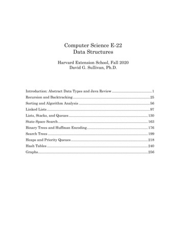
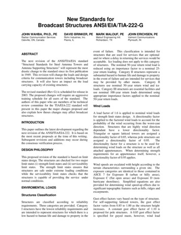
responses are modified after analysis to account for thedynamic characteristics of wind load on guyedstructures. A 1.25 amplification factor to account fordynamic interaction effects is proposed to be applied tothe gust effect factor for structures supported onbuildings or other structures. A gust effect factor of1.00 is used for determining the strength requirementsof appurtenances.A patch loading is introduced for tapered selfsupporting latticed towers that have extended straightportions or portions with significantly reduced legslopes. The patch loading is intended to simulate thedynamic wind loading effects on such structures.Figure 1: Wind MapIce LoadsA load factor of 2.0 is applied to the nominal radialthickness of ice as opposed to the weight of ice or to theprojected area of ice. For guyed masts, a 50 degree Ftemperature drop is to be considered for the icecondition. The weight of ice on a member is calculatedby considering the factored radial thickness of icearound a cylinder that circumscribes the member. Theprojected area of ice is calculated by considering twicethe factored radial thickness of ice. The additionalprojected area due to ice is considered round for thepurposes of calculating drag factors.Nominal 3-second gust wind speeds that are to beconsidered to occur simultaneously with ice areprovided. A load factor of 1.0 is applied to windloading for the ice condition since wind pressure isapplied to a factored ice thickness. Ice loads areescalated with height since ice accumulation is knownto increase with wind speed. Ice Map is shown inFigure 2.
Figure 2: Ice MapEarthquake LoadsANALYSIS METHODSEarthquake loads rarely govern the design of broadcastantennas and their supporting structures; however, thesestructures require special considerations of theirresponse characteristics in regions of high seismicity.The standard provides design criteria to insuresufficient strength and stability to resist the effects ofseismic ground motions for self-supporting and guyedantenna supporting structures.Unless otherwiserequired, earthquake effects are only specified to beconsidered in very limited areas of high seismicity.Serviceability Limit StatesLimit state deformations under service load conditionsare provided in the standard. The service loadcondition is defined as a 60 mph wind speed without iceusing an importance factor of 1.00, a gust effect factorequal to 1.0 and a directionality factor of 0.85 for allstructures. Structures are limited to 4 degrees twist orsway rotation and a horizontal displacement equal to5% of the height of the structure. In addition, morestringent rotation requirements are provided forstructures supporting microwave antennas.This new section of the standard includes the minimumacceptable models of analysis with requirements toconsider the effects of displacements on member forces(P- effects).For self-supporting lattice towers, the analysis modelshould be either: (a) an elastic three-dimensional trussmodel made up of straight members pin connected atjoints producing only axial forces in the me mbers, or(b) an elastic three-dimensional frame -truss modelwhere continuous members (legs) are modeled as 3-Dbeam elements while other members are modeled as 3D truss elements.For self-supporting pole structures, the analysis modelshould be an elastic three-dimensional beam-columnmodel producing moments, shears and axial forces inthe structure with a minimum of five beam elements perpole section.For guyed masts, the analysis model should be either:(a) an elastic three-dimensional beam-column on nonlinear elastic supports where the mast is modeled asequivalent three-dimensional beam-column memberssupported by cable members with a minimum of fivebeam elements in each span; (b) or an elastic three-
dimensional truss model made up of straight membersor cables pin connected at joints producing only axialforces in the members; or (c) an elastic threedimensional frame -truss model were the continuousmembers (legs) are modeled as 3-D beam elementswhile other members are modeled as 3-D trusselements.Modified Guyed Mast ResponseIn addition, section 3.0 of the standard provides aprescribed method of modifying guyed mast responsesto account for the dynamic effects of wind loading ontaller guyed masts. The procedure redistributes theloads to account for the effects of the dynamic loadresponse. Unlike other approximate methods such aspatch-loading techniques, the new procedure generatesan estimate of the peak dynamic response envelopesbased on the analysis results from the static analysis.The non-wind load responses are separated from thewind load responses and the resulting wind loadcomponents are then modified. By employing scalingfactors, which are determined based on structureproperties and geometry, the wind-induced dynamiccomponent of the mast axial, shear, torsion, bendingmoment and guy forces are obtained. Calibrationstudies indicate that the prescribed method provides areliable prediction of the dynamic effects of wind loads.FOUNDATIONSThe design of communication structure foundations isdominated by unusual and unique design andinstallation techniques.When combined with themarked change in the design criteria that will belegislated by revision G to create loads, reaction setsand subsequent foundation designs, it is important tounderstand the changes that will affect foundationdesigns. The foundation chapter has been updated toimprove and replace many older design practices and toprovide more concise design information. The changesimplemented are intended to provide the designer theinformation required to design a foundation that iseconomical and consistent with limit states designmethodology. Changes contained within the newfoundation chapter include the elimination of “normalsoil”, the inclusion of assumed soil design parametersfor sites lacking geotechnical information and a moreconcise presentation of the design parameters requiredto maintain foundation stability.IMPACT ON THE DESIGNBROADCAST STRUCTURESOFNEWRevision G will introduce new variables to consider forthe design of broadcast structures. The proposed designmethodology will allow the design criteria for astructure to be fine tuned based on site-specific data asopposed to generic criteria used in previous additions ofthe standard.Procurement and user guidelines are provided in anannex to identify site-specific and/or suggestedsupplementary requirements for the design of astructure. Default parameters are provided when sitespecific conditions are not available. The defaultvalues are intended to result in design criteria similar tothe generic criteria used in the existing version of thestandard. Following is a description of some of themajor site-specific and supplementary requirementsissues to consider for a structure. Some of these issuesare also appropriate to consider when using the existingstandard.The standard provides county listings of wind, ice andearthquake loading criteria, however, when morestringent loadings are know to exist or are required tosatisfy a local requirement, the more stringentrequirements should be specified. For example, somecounties are listed as being in a special wind or iceloading area. Local authorities in these areas may havemore stringent loading requirements. Some areas maybe subject to in-cloud icing which may be a morestringent ice loading condition. These conditions mustbe considered as supplementary conditions and beincluded in the specification for a structure.Criteria for determining loading criteria are providedwithin the standard. This is required for locationsoutside the United States and may be also be used todetermine loading criteria for counties located inspecial loading regions. Minimum design valuesapplicable to any location are provided. A means forhandling specifications that involve “survival” or“withstand” conditions is also clarified in the standard.It is not uncommon to have wind speeds reported overdifferent averaging periods (for example, a 1 minuteaverage wind speed or an average hourly wind speed).A conversion table (Table 1) is provided to convertwind speeds to 3-second gust wind speeds which are tobe used with the standard.
3-sec 3106109113Table 1: Wind Speed ConversionsThe category of a structure must be established basedon the reliability requirements for the structure. Thedesign loadings for a structure are modified accordingto the structure’s category. The standard provides forprogressively more stringent loading as the reliabilityrequirements or importance of a structure increases(category 1 to category 3). Importance relates to theconsequences of failure to human life or property aswell as to the type of communication services that aresupported by a structure.The use of differentclassifications results in cost savings for structures thathave lower reliability requirements.The defaultcategory is specified as being category 2.The terrain surrounding a site significantly affects windloading for a structure. The proposed standard allowsthe flexibility to consider various types of terrain(exposure B for rough surfaces, exposure C for flatsurfaces, and exposure D for smooth surfaces).Exposure D results in the most stringent loading.Previous versions of the standard were based onexposure C conditions. Allowing the use of otherexposures results in site-specific design criteria for astructure based on its surrou
Broadcast Structures ANSI/EIA/TIA -222-G JOHN WAHBA, PH.D., PE DAVID BRINKER, PE MARK MALOUF, PE JOHN ERICHSEN, PE Radian Communication Services Rohn Industries, Inc. Malouf Engineering Intl. Valmont Communications Oakville, ON, Canada Peoria, IL Richardson, TX Plymouth, IN event of failure. This classification is intended for ABSTRACT The next revision of the ANSI/TIA/EIA File Size: 583KBPage Count: 7